
PROPELLER SHAFT
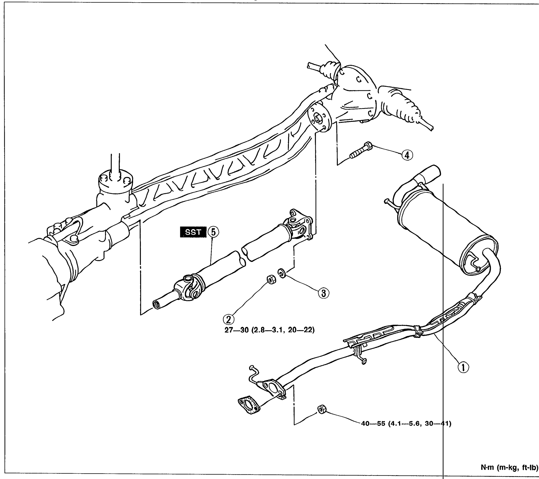
L-3parts diagramREMOVAL / INSPECTION / INSTALLATION
Propeller shaft removal, inspection, installation
- 1Remove in the order shown in the figure, referring to Removal Note.
 05U0LX-005
 - 2Inspect all parts and repair or replace as necessary.
- 3Install in the reverse order of removal, referring to Installation Note.
Parts DiagramFig. fig1
| Specification | Value |
|---|---|
| Bolt torque (item 4)Propeller shaft to differential flange | 27 - 30N·m |
| Nut torque (item 2)Exhaust pipe mounting | 40 - 55N·m |
Bolt torque (item 4)Propeller shaft to differential flange
27 - 30N·m
Nut torque (item 2)Exhaust pipe mounting
40 - 55N·m
Removal Note
Propeller shaft
Removal Note - Propeller shaft
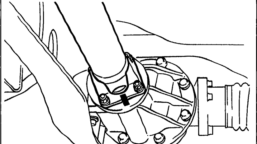
- 1Before removing the propeller shaft, mark the flanges for correct installation.
 05U0LX-006