
Parts Diagrams
Exploded views and component parts lists from the service manual — 307 diagrams across 16 sections, 3282 individual parts
Engine
B10 diagrams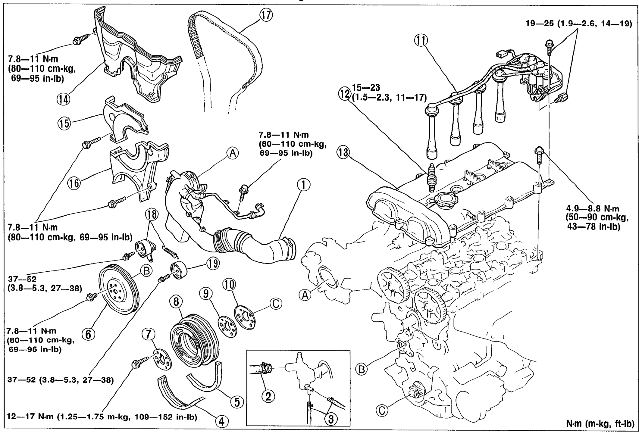
TIMING BELT — Removal / Installation
B-12Exploded view of the timing belt and surrounding components with numbered balloon callouts (1-19) and torque specifications. Shows air intake pipe, upper radiator hose, water hoses, drive belts, alternator, water pump pulley, crankshaft pulley, timing belt guide plates, ignition coil, spark plug, cylinder head cover, timing belt covers (upper/middle/lower), timing belt, tensioner with spring, and idler pulley. Torque values shown in N·m (m-kg, ft-lb).
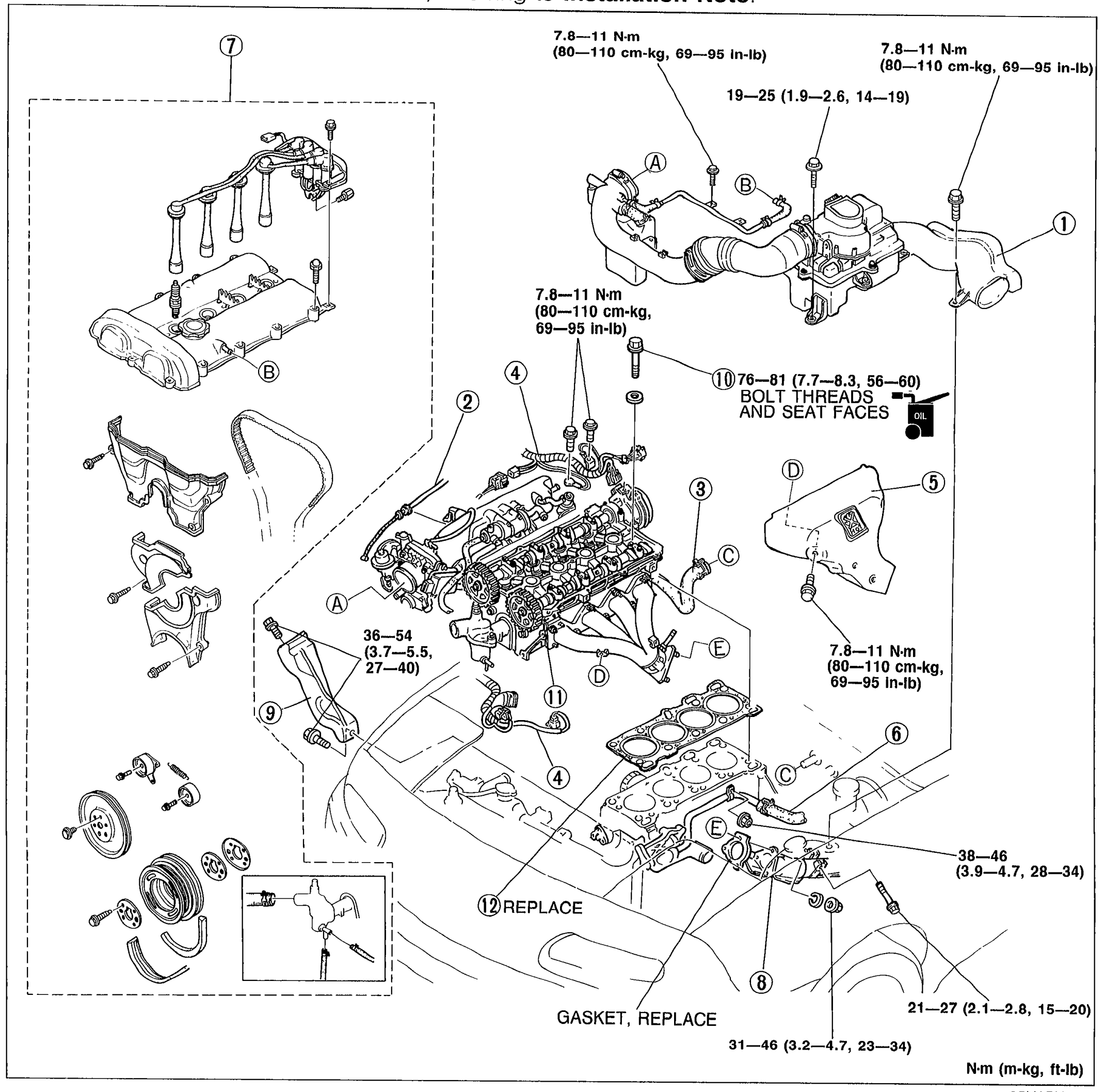
ON-VEHICLE MAINTENANCE — CYLINDER HEAD GASKET Replacement
B-16Exploded view of the cylinder head gasket replacement showing components with numbered balloons (1-12) and tightening torque callouts labeled A through E. Includes timing belt cover, exhaust manifold, intake manifold, cylinder head, crankshaft pulley, water pump area components.
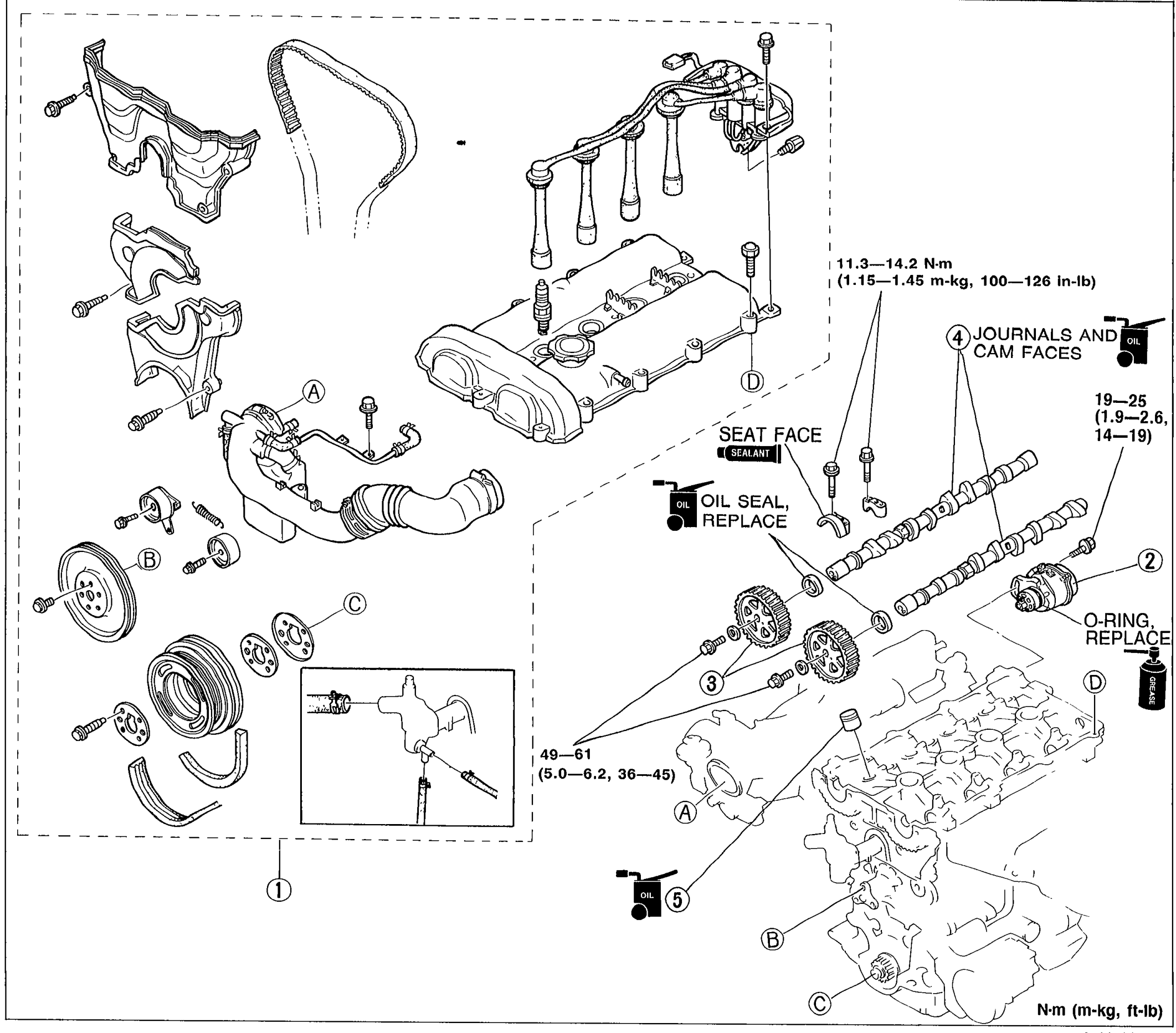
ON-VEHICLE MAINTENANCE — HLA Removal / Installation
B-20Exploded view of HLA (Hydraulic Lash Adjuster) and related components: timing belt cover, crankshaft pulley, camshaft pulleys, camshafts, oil seals, O-rings, and journal/cam faces. Numbered balloons 1-5 with torque callouts A through D.
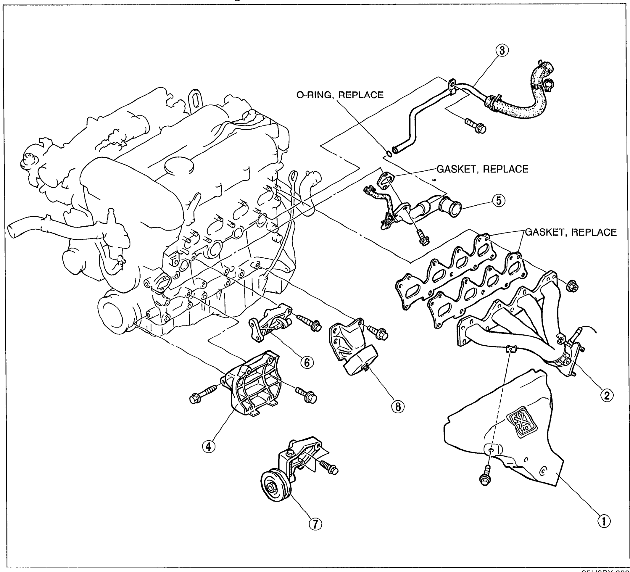
ENGINE STAND MOUNTING
B-34Exploded view of engine accessories to remove before stand mounting. Shows the engine with eight numbered balloon callouts pointing to: exhaust manifold insulator (1), exhaust manifold (2), water bypass pipe (3), A/C compressor bracket (4), water inlet pipe (5), P/S oil pump bracket (6), idler A/C (7), left engine mount (8). 'O-RING, REPLACE' and 'GASKET, REPLACE' replacement notes are labeled with arrows.
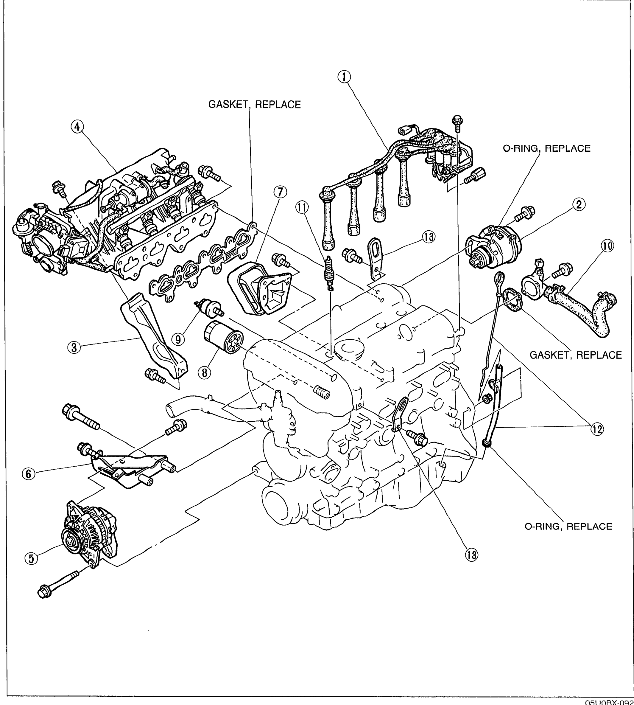
DISASSEMBLY
B-37Exploded view of auxiliary engine parts disassembly. The engine is shown with 13 numbered balloon callouts pointing to: ignition coil and high-tension lead (1), crank angle sensor (2), manifold bracket (3), intake manifold assembly (4), alternator (5), alternator bracket (6), right engine mount (7), oil filter (8), oil pressure gauge sender unit (9), water outlet pipe (10), spark plug (11), oil level gauge and pipe (12), engine hanger (13 - two locations). Replacement notes 'GASKET, REPLACE' and 'O-RING, REPLACE' are shown with arrows.
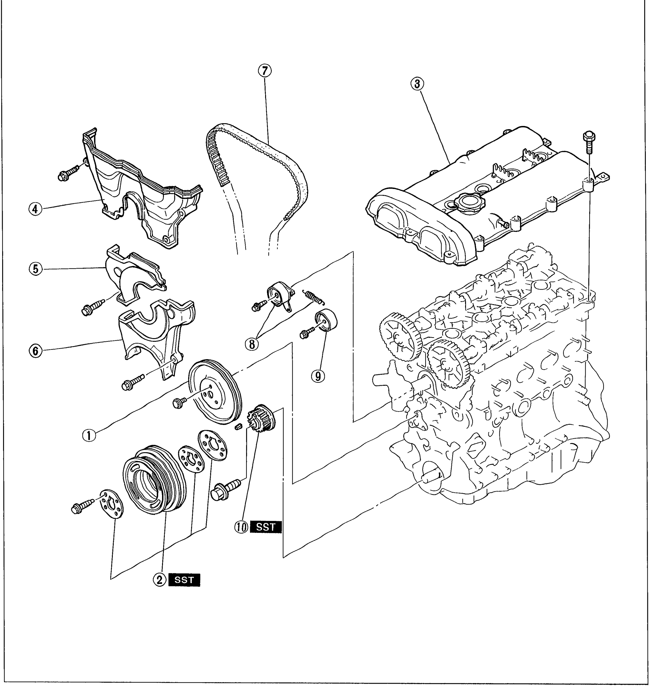
DISASSEMBLY
B-38Exploded view of timing belt assembly disassembly. Shows 10 numbered balloon callouts: water pump pulley (1), crankshaft pulley (2 - marked SST), cylinder head cover (3), timing belt cover upper (4), timing belt cover middle (5), timing belt cover lower (6), timing belt (7), tensioner/tensioner spring (8), idler (9), timing belt pulley (10 - marked SST). Items 2 and 10 require SST.
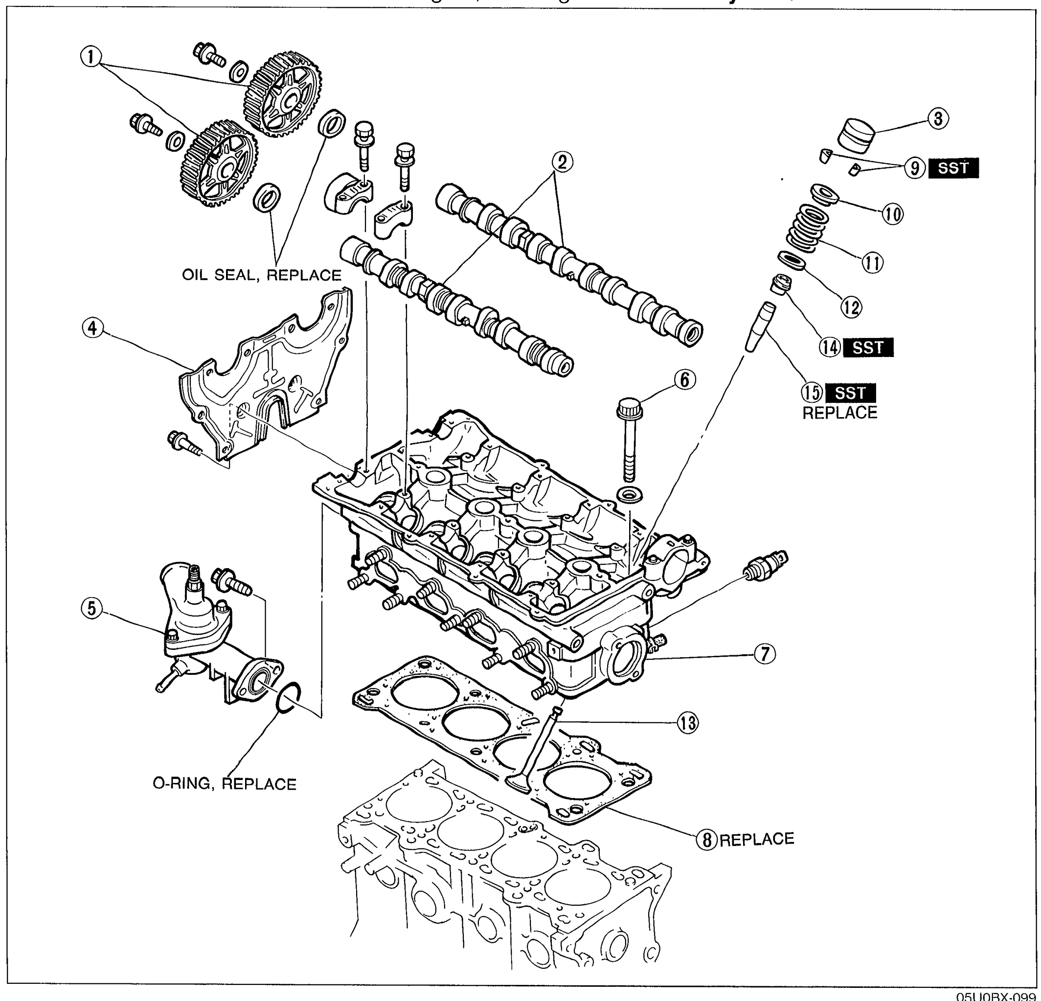
DISASSEMBLY
B-40Exploded view of cylinder head disassembly with 15 numbered balloon callouts: camshaft pulley (1), camshaft (2), HLA (3), seal plate (4), thermostat housing (5), cylinder head bolt (6), cylinder head (7), cylinder head gasket (8 - REPLACE), valve keeper (9 - SST), valve spring seat upper (10), valve spring (11), valve spring seat lower (12), valve (13), valve seal (14 - SST), valve guide (15 - SST, REPLACE). Replacement notes include 'OIL SEAL, REPLACE' and 'O-RING, REPLACE'.
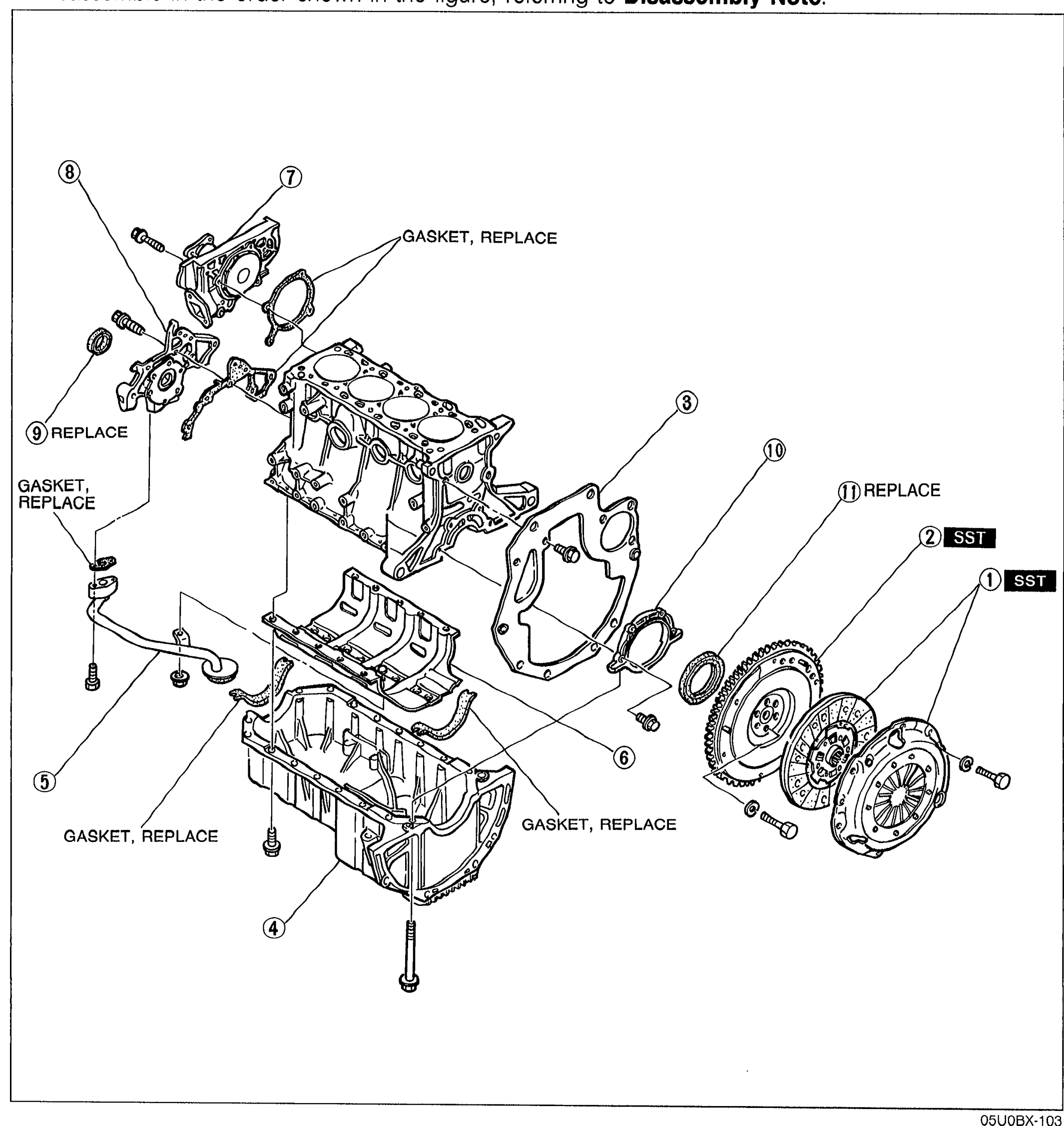
DISASSEMBLY
B-43Exploded view of cylinder block external parts disassembly with 11 numbered balloon callouts: clutch cover/clutch disc (1 - SST), flywheel (2 - SST), end plate (3), oil pan (4), oil strainer (5), oil pan baffle (6), water pump (7), oil pump (8), front oil seal (9 - REPLACE), rear cover (10), rear oil seal (11 - REPLACE). Multiple 'GASKET, REPLACE' notes mark gasket positions.
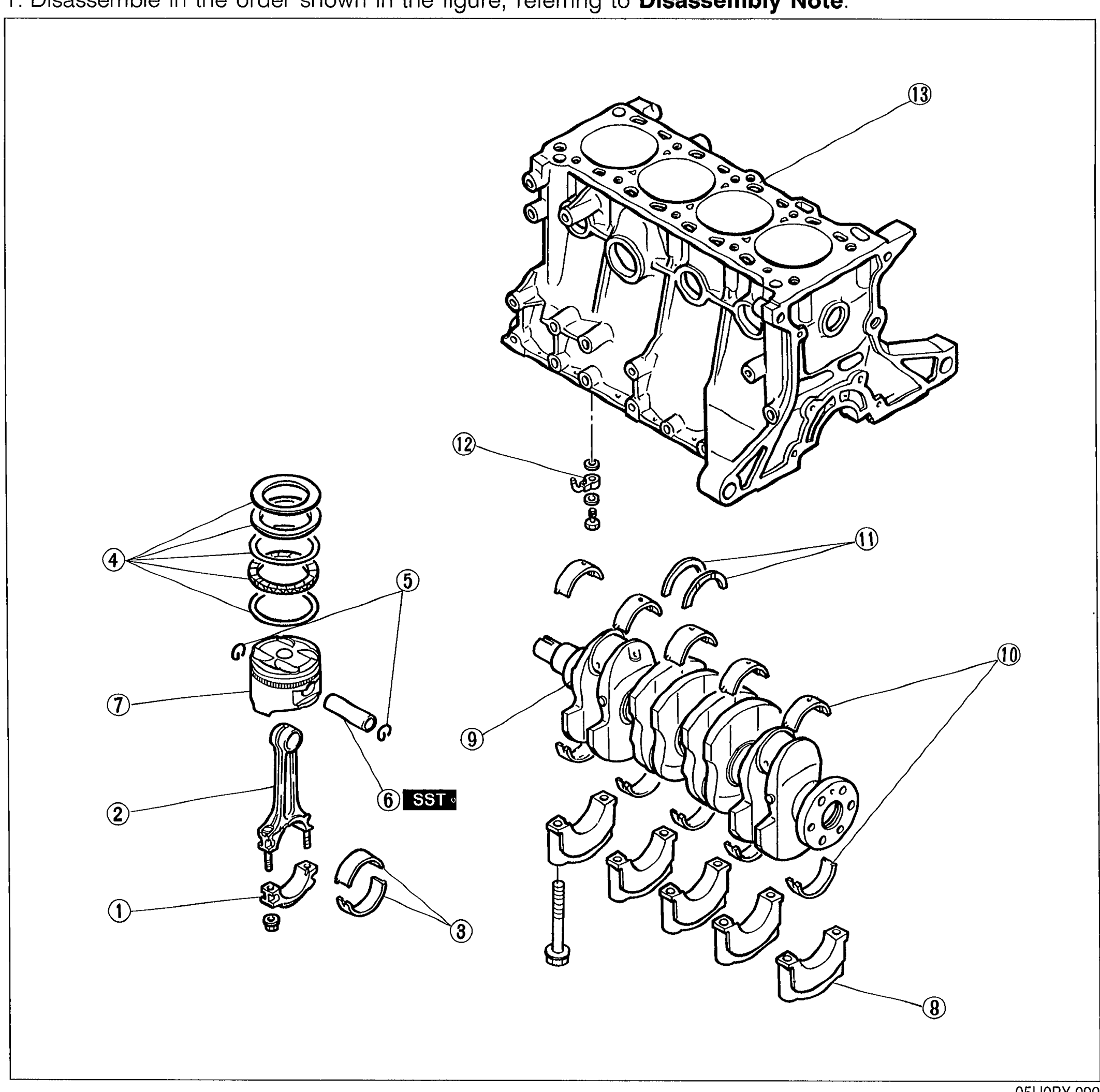
DISASSEMBLY — CYLINDER BLOCK (INTERNAL PARTS)
B-45Exploded view of the B6 cylinder block internal parts with 13 numbered callouts: connecting rod cap, connecting rod, connecting rod bearing, piston ring, piston pin clip, piston pin (SST), piston, main bearing cap, crankshaft, main bearing, thrust bearing, oil jet, and cylinder block. Callout 6 is tagged 'SST'.
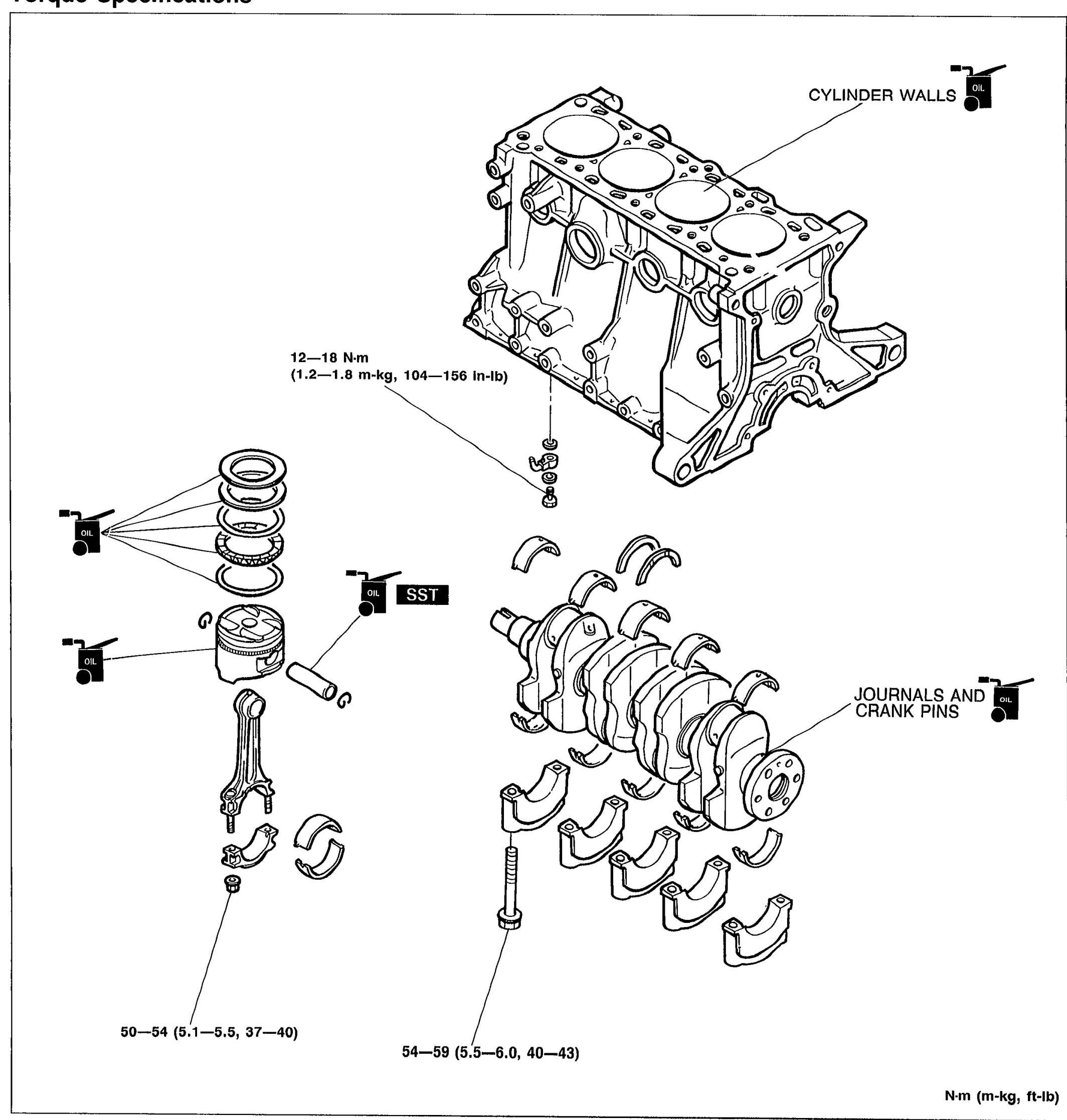
ASSEMBLY — CYLINDER BLOCK (INTERNAL PARTS)
B-61Exploded view of cylinder block internal parts assembly: cylinder block at top with arrow callouts for piston rings (3 rings stacked), piston with pin, connecting rod with bearing, crankshaft with main bearings and crankshaft thrust bearings. Oil/lubrication icons indicate where engine oil should be applied: 'CYLINDER WALLS' and 'JOURNALS AND CRANK PINS'. SST icon marks the piston pin installer tool location. Torque values shown: 12—18 N·m (1.2—1.8 m-kg, 104—156 in-lb) for cylinder head bolts area; 50—54 N·m (5.1—5.5, 37—40 ft-lb) for main bearing caps; 54—59 N·m (5.5—6.0, 40—43 ft-lb) for connecting rod caps. Units note at bottom: N·m (m-kg, ft-lb).
Lubrication System
D3 diagrams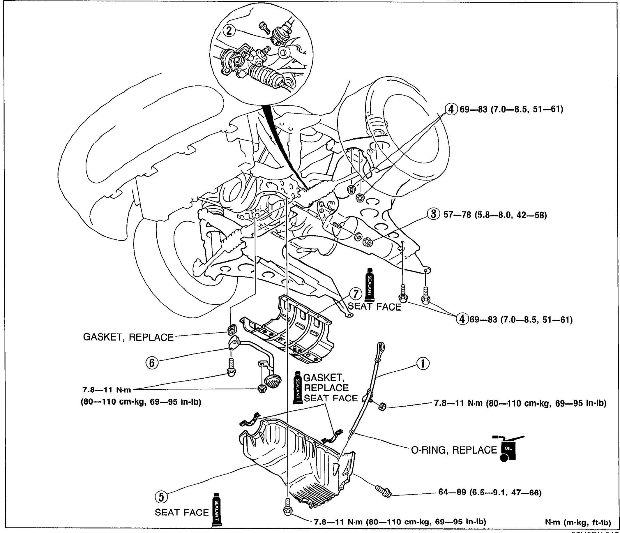
OIL PAN
D-6Exploded view of the oil pan assembly area: front crossmember, engine mount, oil pan, oil strainer, oil pan baffle, and intermediate shaft, with numbered balloon callouts (1)-(7), tightening torque values, gasket/seal replacement notes, and 'SEAT FACE' markers.
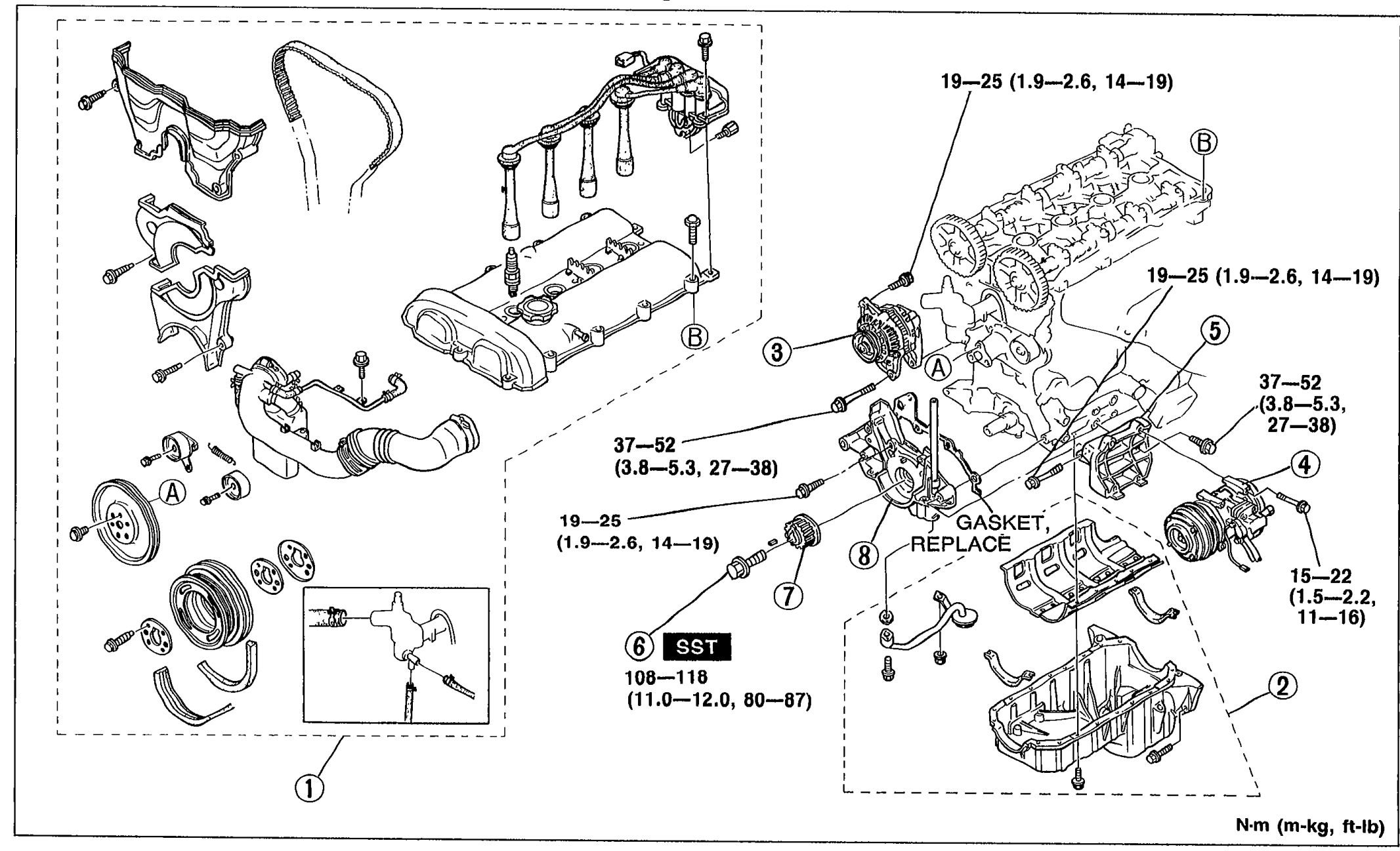
OIL PUMP
D-9Exploded view of the oil pump assembly area: timing belt cover, alternator, A/C compressor and bracket, pulley lock bolt, timing belt pulley, oil pump, oil pan, and SST 'lock tool' usage. Eight numbered balloon callouts (1)-(8) with tightening torques.
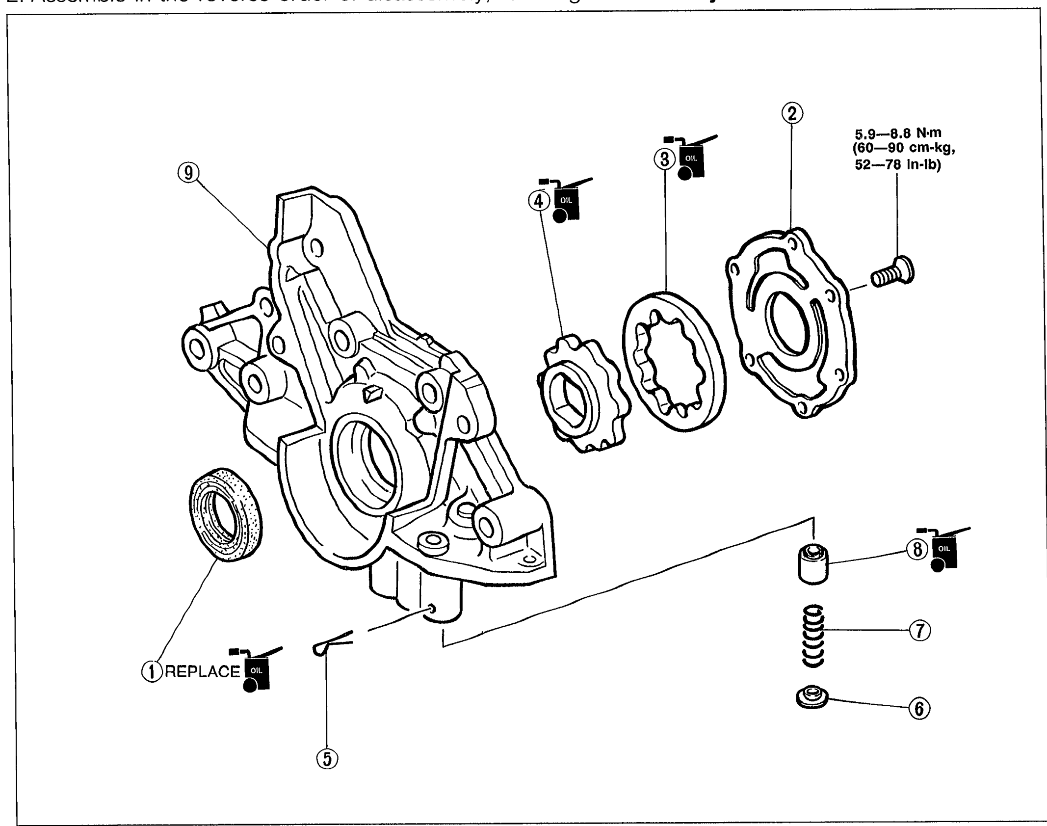
OIL PUMP
D-11Exploded view of the oil pump assembly: pump body (9), oil seal (1, REPLACE), roll pin (5), pressure spring (7), control plunger (8), spring seat (6), inner rotor (4), outer rotor (3), and pump cover (2). Nine numbered balloon callouts identify each part.
Cooling System
E2 diagrams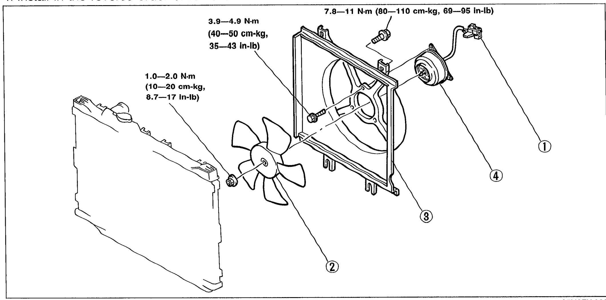
FAN MOTOR
E-12Exploded view of the cooling fan / radiator cowling assembly. Numbered callouts: 1 cooling fan connector, 2 cooling fan, 3 radiator cowling, 4 fan motor. Tightening torques shown: 7.8-11 N-m (80-110 cm-kg, 69-95 in-lb) on the fan motor mount bolts, 3.9-4.9 N-m (40-50 cm-kg, 35-43 in-lb) on the upper cowling bolt, 1.0-2.0 N-m (10-20 cm-kg, 8.7-17 in-lb) on the fan blade nut.
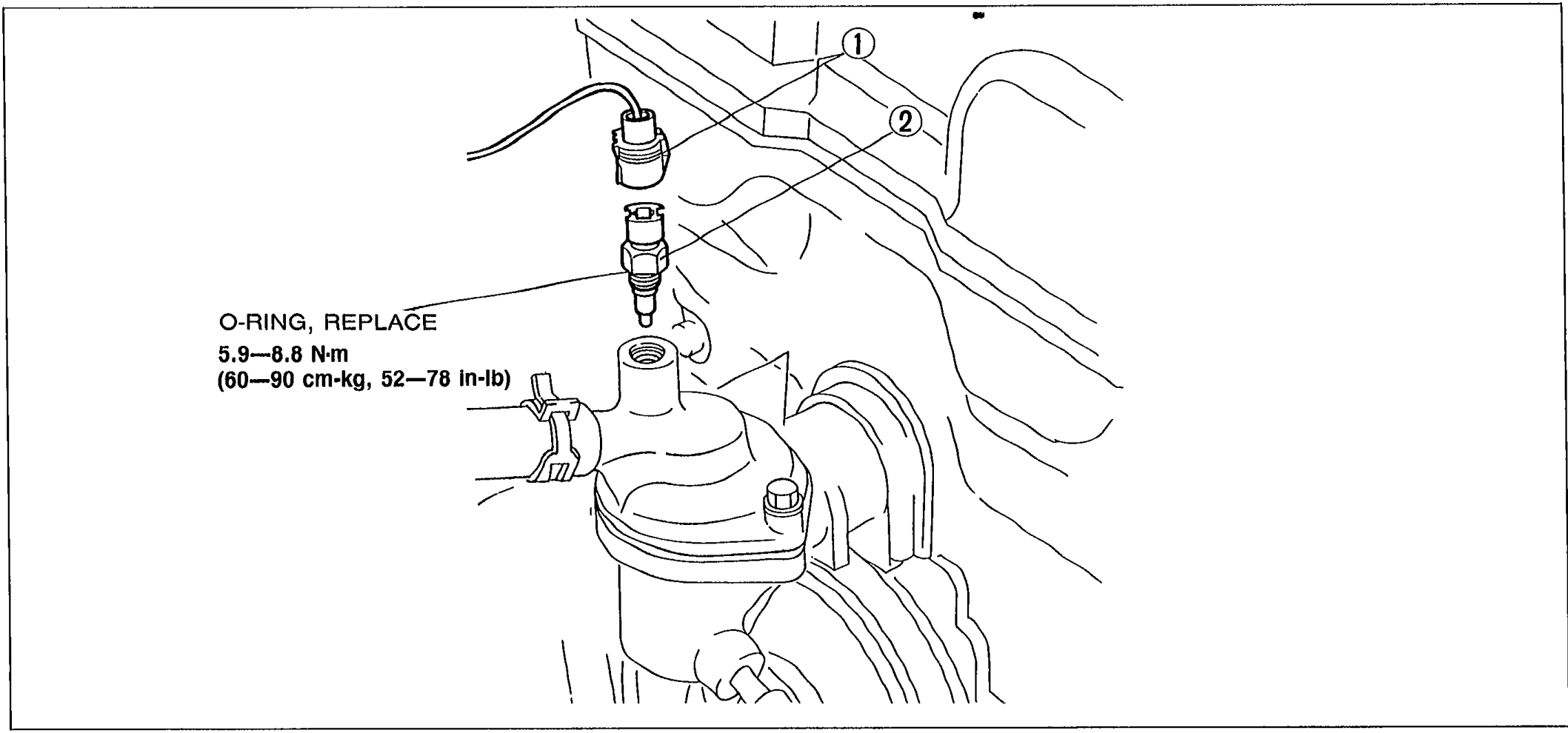
WATER THERMOSWITCH
E-13Engine bay view of the water thermoswitch removal showing callouts: 1 water thermoswitch connector, 2 water thermoswitch. Annotation indicates 'O-RING, REPLACE' and tightening torque 5.9-8.8 N-m (60-90 cm-kg, 52-78 in-lb).
Fuel and Emission Control Systems
F7 diagrams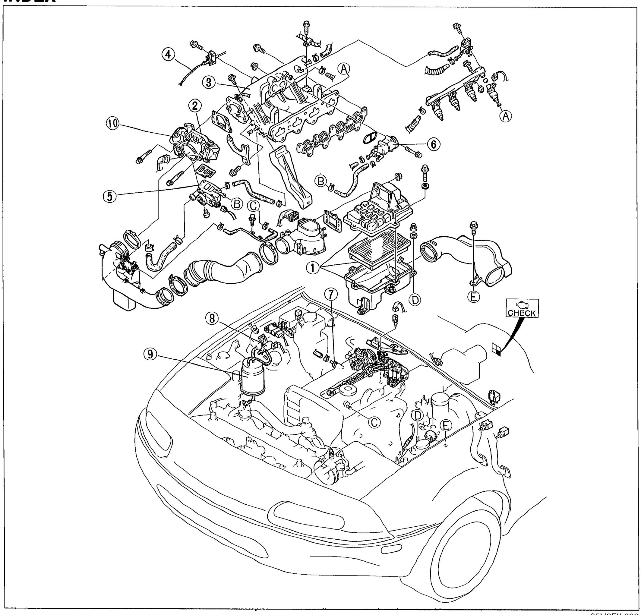
INDEX
F-2Exploded view of engine bay components used as the visual index for the Fuel and Emission Control Systems section. Shows the engine, intake manifold, throttle body, air cleaner, vehicle silhouette with hood open, and numbered balloon callouts 1-10 plus lettered callouts A-E pointing to component locations. A CHECK callout pictogram is shown on the right side.
INDEX
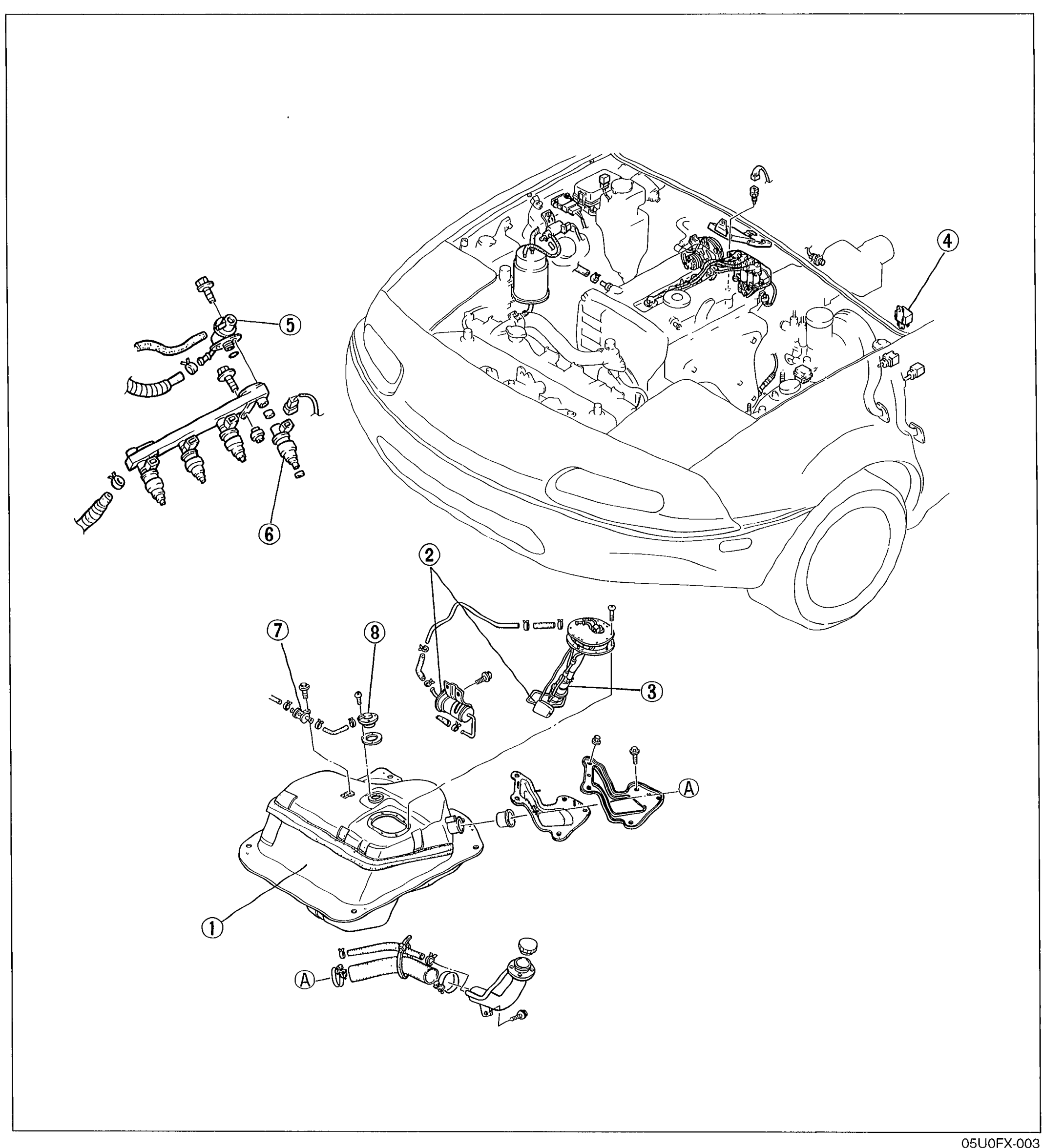
F-3Visual index showing the fuel system with vehicle silhouette. Components called out: fuel tank, injector / fuel rail assembly, pressure regulator, fuel pump, fuel filter, circuit opening relay. Numbered balloons 1-8 and lettered callouts (A) indicate hose/strap locations.
INDEX
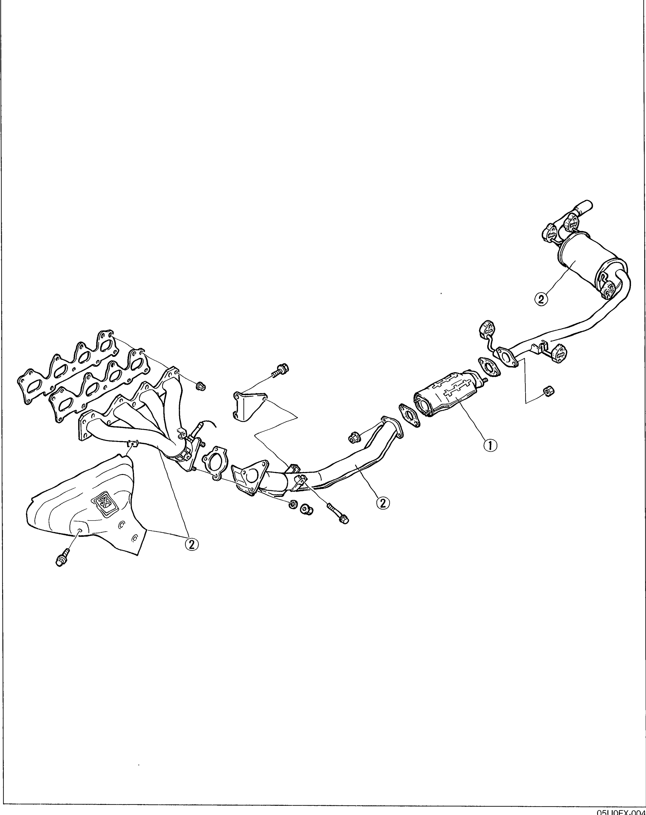
F-4Exploded view of the exhaust system. Shows exhaust manifold (with heat shield), front exhaust pipe, catalytic converter (callout 1), and rear muffler. Numbered balloons: 1 catalytic converter, 2 exhaust components (heat shield, front pipe, muffler).
INTAKE AIR SYSTEM
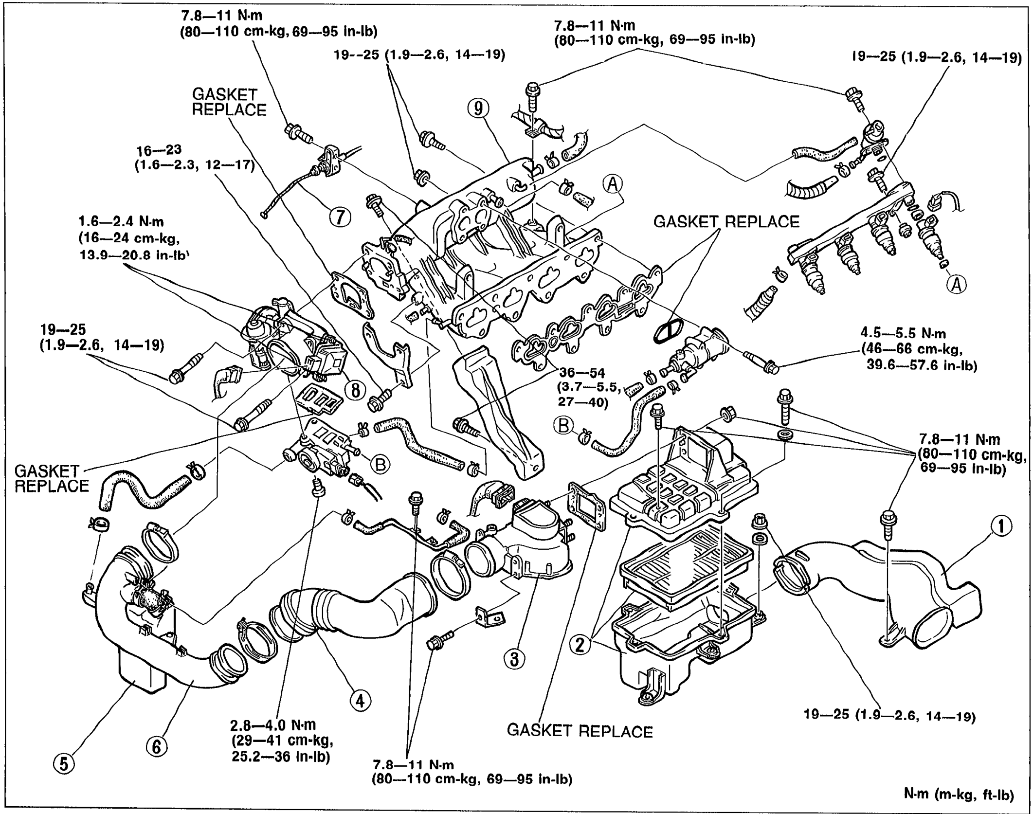
F-92Exploded view of the intake air system showing intake manifold, throttle body, airflow meter, air cleaner, air ducts/hoses, resonance chamber, and air pipe with numbered callouts 1–9 and tightening torque values. 'GASKET REPLACE' callouts shown in multiple locations. Tightening torques in N·m (cm-kg, in-lb) at fastener locations. Letter callouts A and B mark sub-assemblies.
FUEL SYSTEM
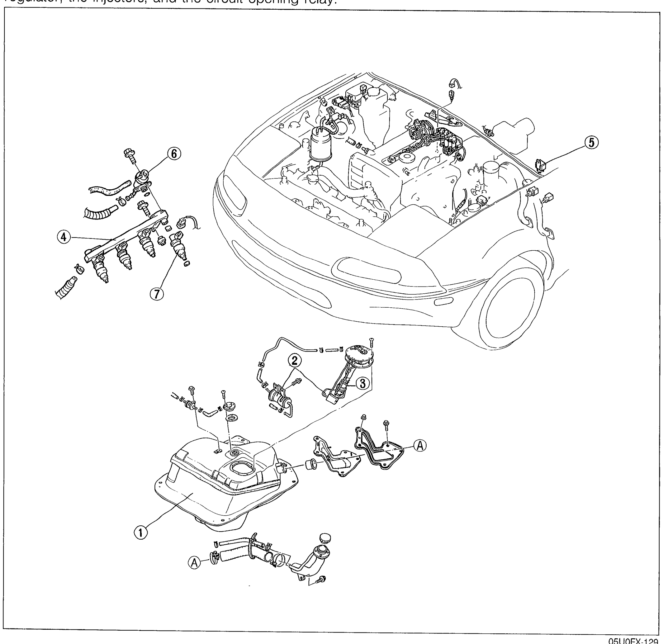
F-100Exploded view of the MX-5 fuel system showing the vehicle front clip with intake manifold, plus separate callouts for components 1 through 7 and two unlabeled hose connections (A). Balloons identify: 1 fuel tank, 2 fuel filter, 3 fuel pump, 4 delivery pipe, 5 circuit opening relay, 6 pressure regulator, 7 injector(s). Hose ends marked 'A'.

FUEL SYSTEM
F-105Small ref-code header (no visible exploded view on this page — likely a label tying the parts list above to the figure on page F-104). Placed at the upper right of the page.
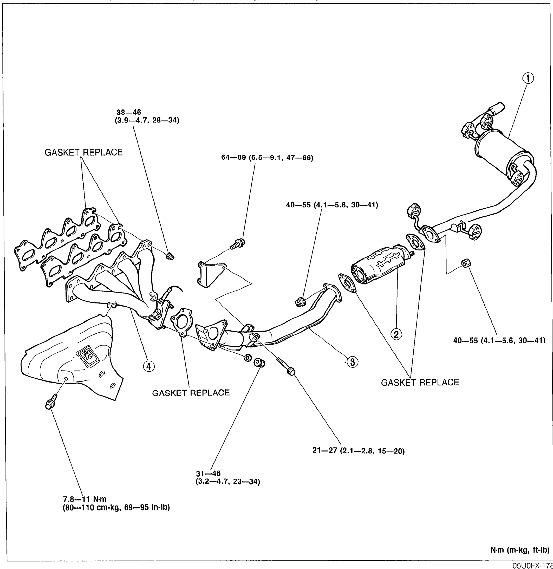
EXHAUST SYSTEM
F-115Exploded view of the complete exhaust system: exhaust manifold (4) with heat shield, front exhaust pipe (3) with catalytic converter (2) and main silencer (1). Torque callouts in N·m (m-kg, ft-lb) are placed at each fastener: 38—46 (3.9—4.7, 28—34) at exhaust manifold-to-head, 64—89 (6.5—9.1, 47—66) at manifold-to-front pipe, 40—55 (4.1—5.6, 30—41) at catalytic converter joints (two locations), 21—27 (2.1—2.8, 15—20) at exhaust hanger, 31—46 (3.2—4.7, 23—34) at front pipe joint, 7.8—11 N·m (80—110 cm-kg, 69—95 in-lb) on heat shield. 'GASKET REPLACE' notes at three gasket locations. Balloon callouts numbered 1–4 mark the four main components.
Engine Electrical System
G2 diagrams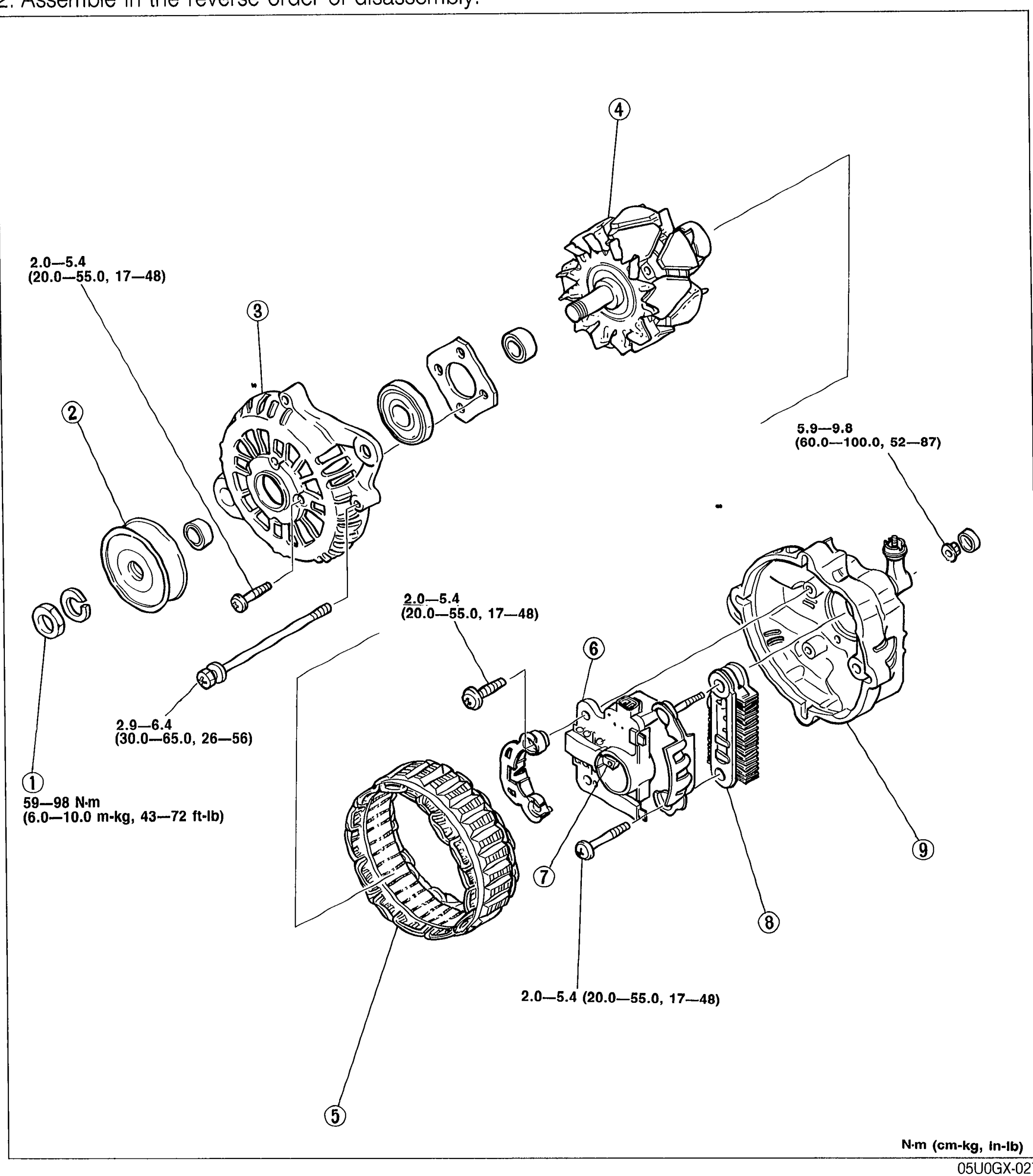
CHARGING SYSTEM - ALTERNATOR Disassembly / Assembly
G-13Alternator exploded view with 9 numbered balloon callouts: 1=Pulley nut, 2=Pulley, 3=Front cover, 4=Rotor, 5=Stator, 6=Brush holder assembly, 7=Brush, 8=Rectifier, 9=Rear cover. Torque values shown next to fasteners: 2.0—5.4 (20.0—55.0, 17—48); 2.0—5.4 (30.0—65.0, 26—56); 5.9—9.8 (60.0—100.0, 52—87); 59—98 N·m (6.0—10.0 m-kg, 43—72 ft-lb). Torque unit legend N·m (cm-kg, in-lb) at bottom right.
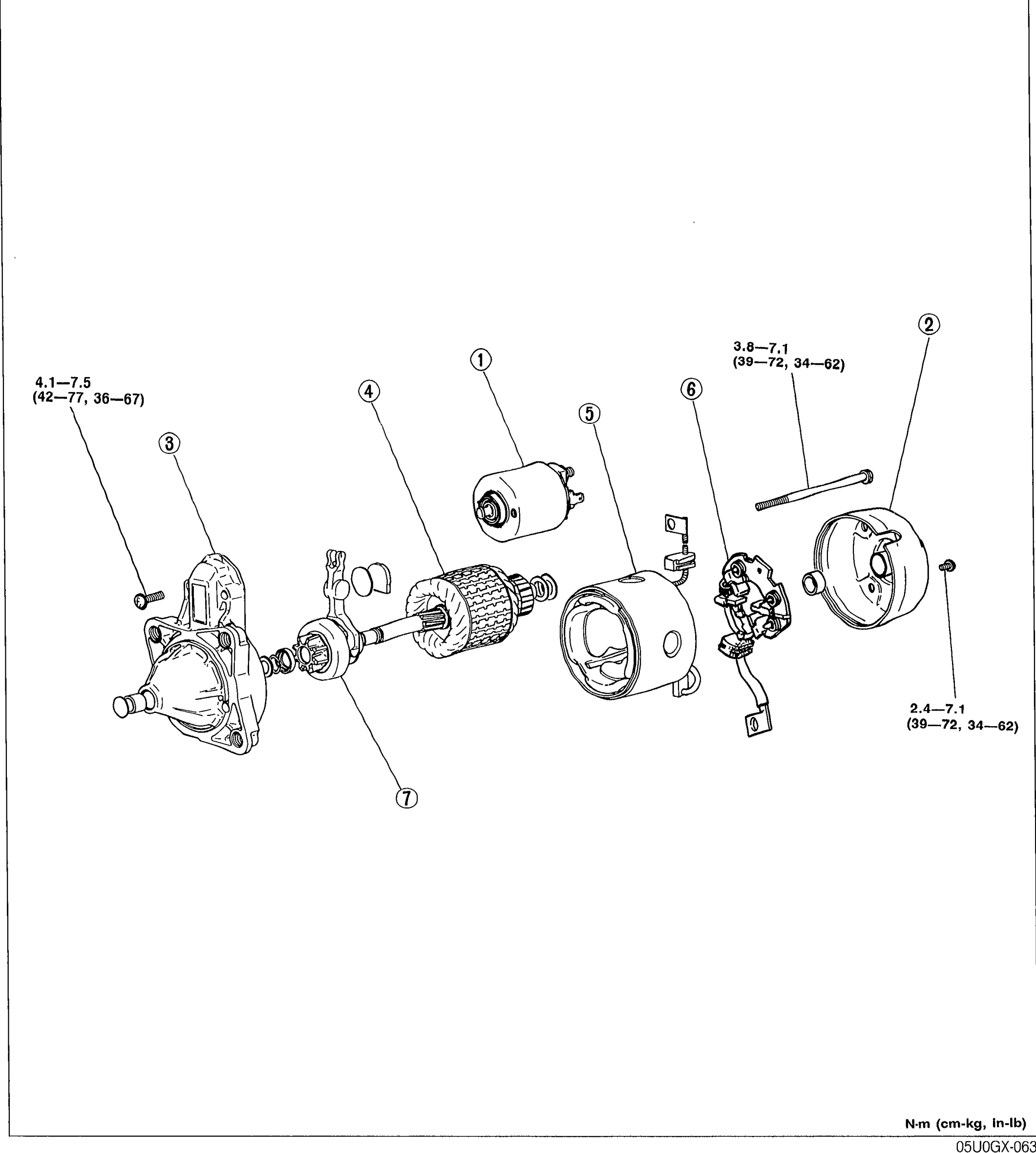
STARTING SYSTEM — Disassembly / Assembly
G-26Exploded view of the starter motor with seven numbered balloons: (1) magnetic switch, (2) rear housing, (3) front cover, (4) armature, (5) yoke assembly, (6) brush holder assembly, (7) drive pinion. Tightening torques are shown next to the front-cover screw (4.1—7.5 N·m / 42—77 cm-kg / 36—67 in-lb) and the rear-housing through-bolts (3.8—7.1 N·m / 39—72 cm-kg, 34—62 in-lb) and the magnetic-switch fastener (2.4—7.1 N·m / 39—72 cm-kg, 34—62 in-lb).
Clutch
H6 diagrams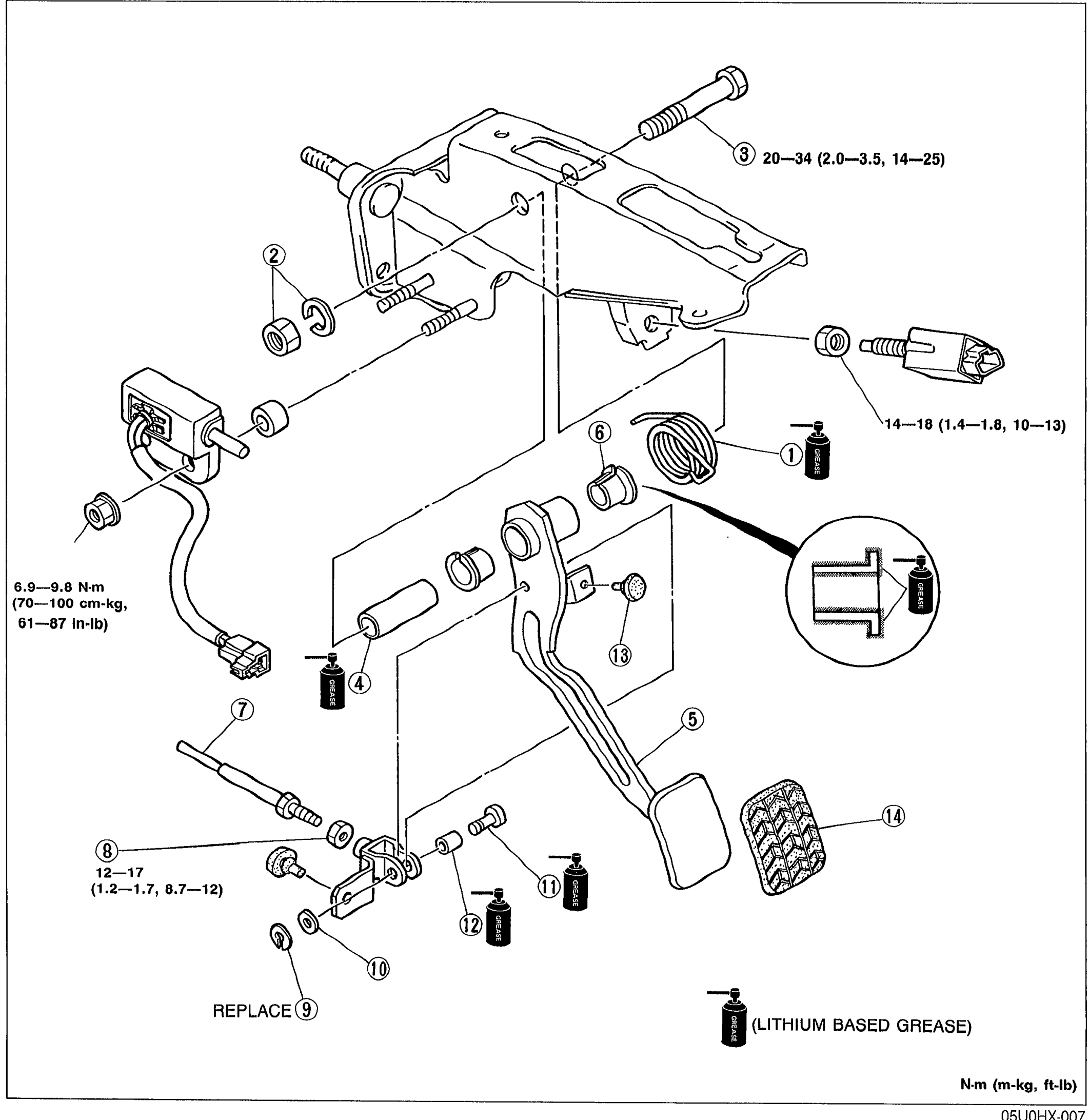
CLUTCH PEDAL — Removal / Inspection / Installation
H-6Exploded view of the clutch pedal assembly with 14 numbered balloons: spring, nut & lock washer, bolt, spacer, clutch pedal, bushings, push rod, nut, clip, wave washer, pin, spacer, stop, pedal pad. Tightening torques labelled at three points; clutch-master-cylinder mount 20—34 N·m (2.0—3.5 m-kg, 14—25 ft-lb); switch 14—18 N·m (1.4—1.8 m-kg, 10—13 ft-lb); push-rod nut 12—17 N·m (1.2—1.7 m-kg, 8.7—12 ft-lb); pedal shaft 6.9—9.8 N·m (70—100 cm-kg, 61—87 in-lb). 'REPLACE' shown next to part 9; 'LITHIUM BASED GREASE' arrow points to bushings/pin.
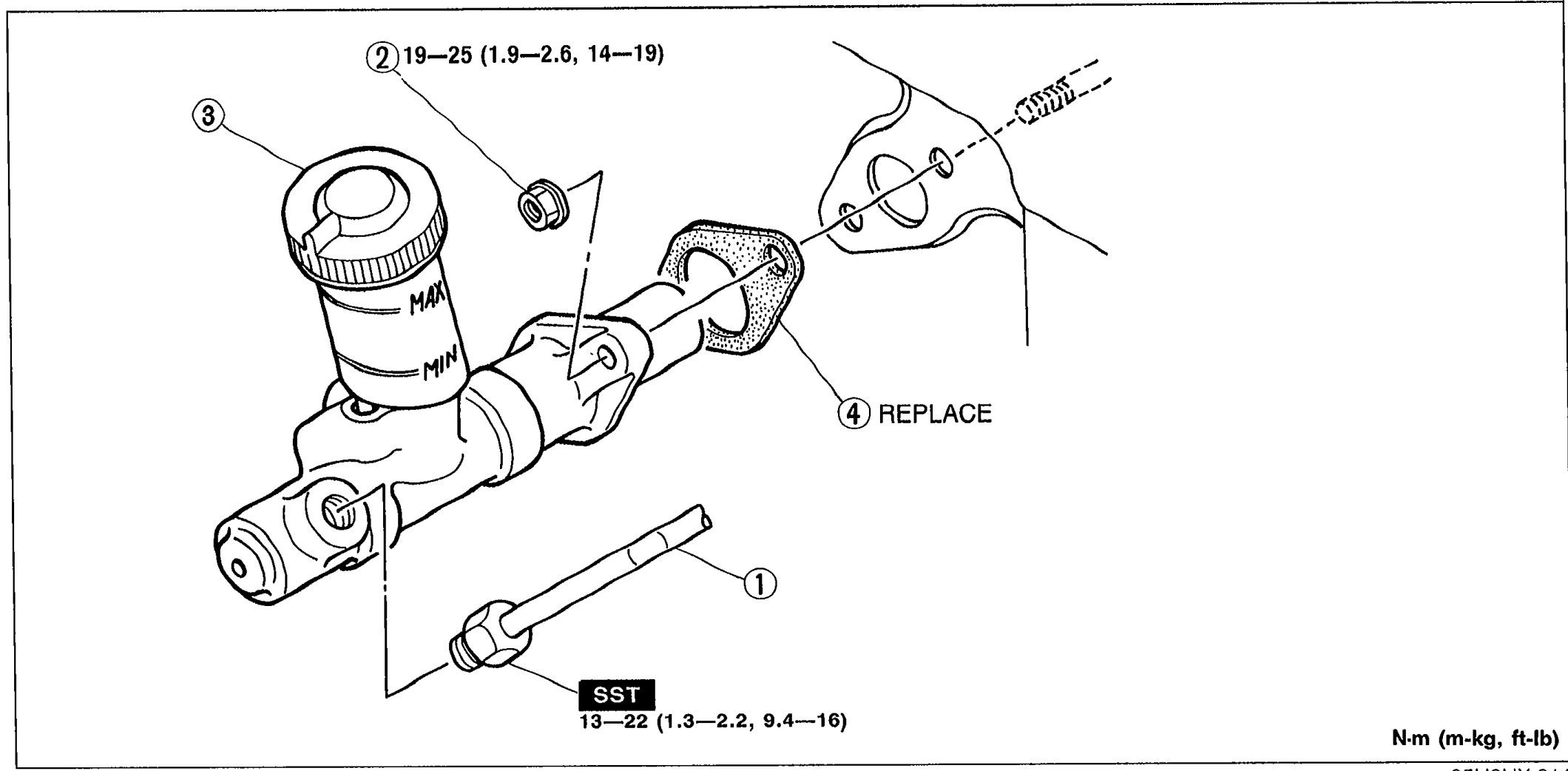
CLUTCH MASTER CYLINDER
H-8Exploded view of the clutch master cylinder assembly. Numbered callouts: (1) Clutch pipe with arrow showing disconnect direction using SST; (2) Nut with tightening torque 19—25 N·m (1.9—2.6 m-kg, 14—19 ft-lb); (3) Clutch master cylinder mounted on bulkhead; (4) Gasket labeled REPLACE. SST is shown with tightening torque 13—22 N·m (1.3—2.2 m-kg, 9.4—16 ft-lb). N·m (m-kg, ft-lb) units label at bottom right.
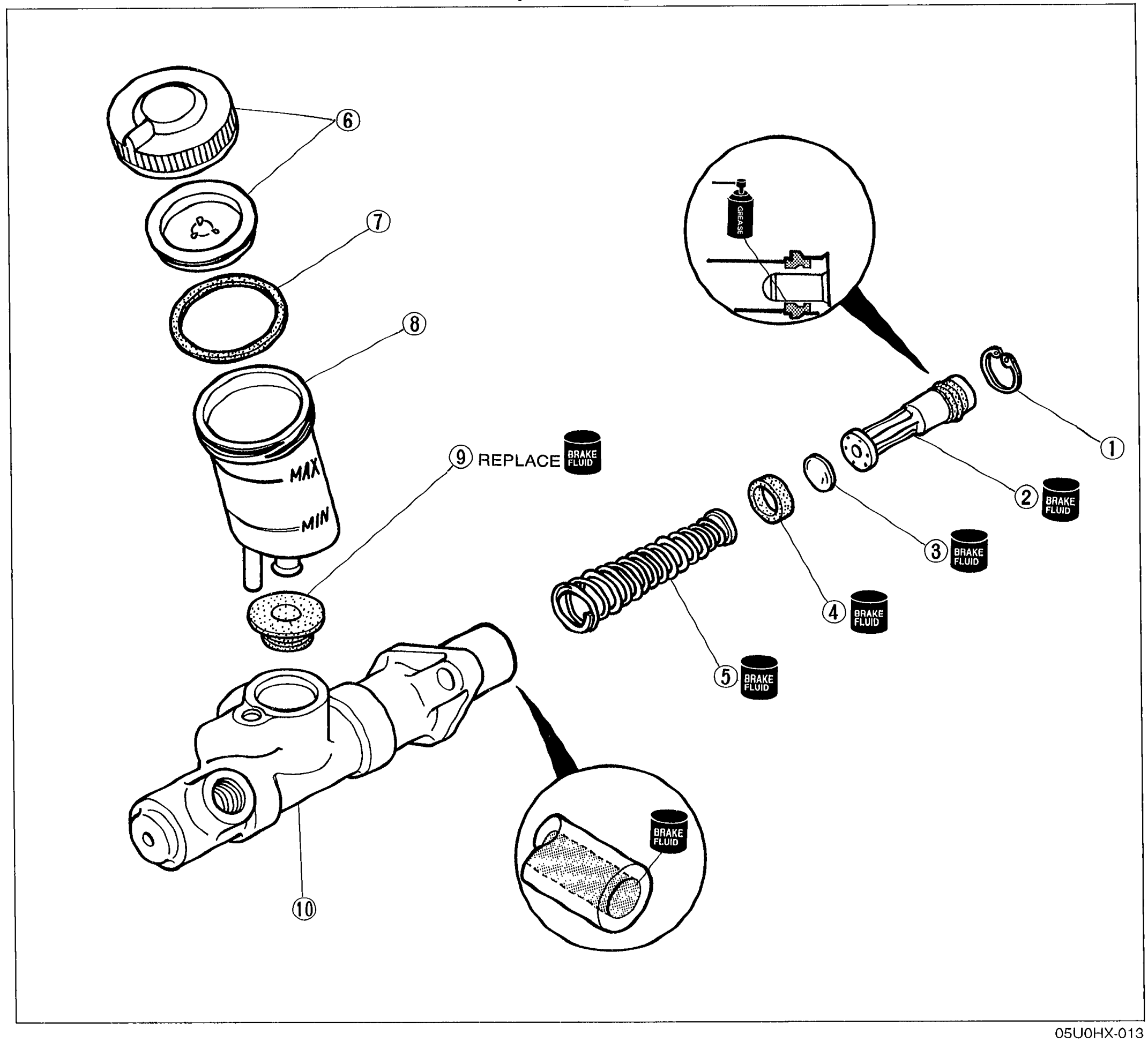
CLUTCH MASTER CYLINDER - OVERHAUL
H-10Exploded view of the clutch master cylinder overhaul components. Numbered callouts: (1) Snap ring at piston end, (2) Piston and secondary cup assembly, (3) Spacer, (4) Primary cup, (5) Return spring, (6) Tank cap, (7) Tank cap baffle, (8) Packing, (9) Reserve tank marked REPLACE BRAKE FLUID, (10) Master cylinder body. Several parts are labeled BRAKE FLUID to indicate lubrication. Detail enlargements show the reservoir cap area and the piston cup orientation.
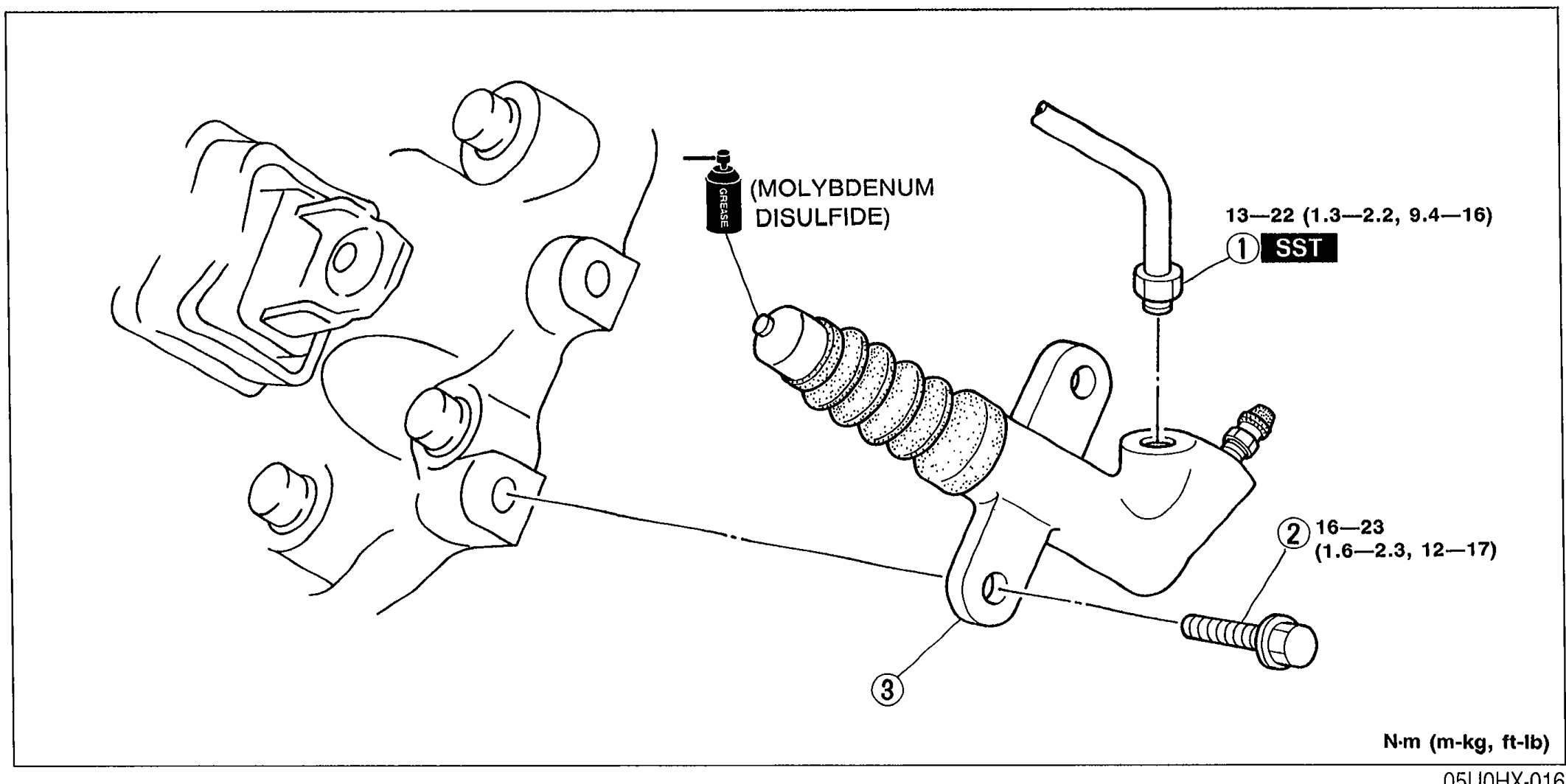
CLUTCH RELEASE CYLINDER
H-12Exploded view of the clutch release cylinder mounted on the transmission. Numbered callouts: (1) Clutch pipe with SST tightening torque 13—22 N·m (1.3—2.2 m-kg, 9.4—16 ft-lb); (2) Bolt with torque 16—23 N·m (1.6—2.3 m-kg, 12—17 ft-lb); (3) Clutch release cylinder. A MOLYBDENUM DISULFIDE grease symbol points to the release cylinder pushrod tip. N·m (m-kg, ft-lb) units label at bottom right.
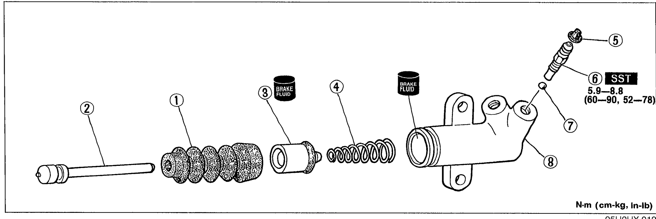
CLUTCH RELEASE CYLINDER - INSTALLATION NOTE / OVERHAUL
H-13Exploded view of the clutch release cylinder overhaul components. Numbered callouts: (1) Boot, (2) Push rod, (3) Piston and cup assembly (with BRAKE FLUID symbol), (4) Spring (with BRAKE FLUID symbol), (5) Bleeder cap, (6) Bleeder screw — tightening torque 5.9—8.8 N·m (60—90 cm-kg, 52—78 in-lb) SST, (7) Steel ball, (8) Release cylinder body. N·m (cm-kg, in-lb) units label at bottom right.
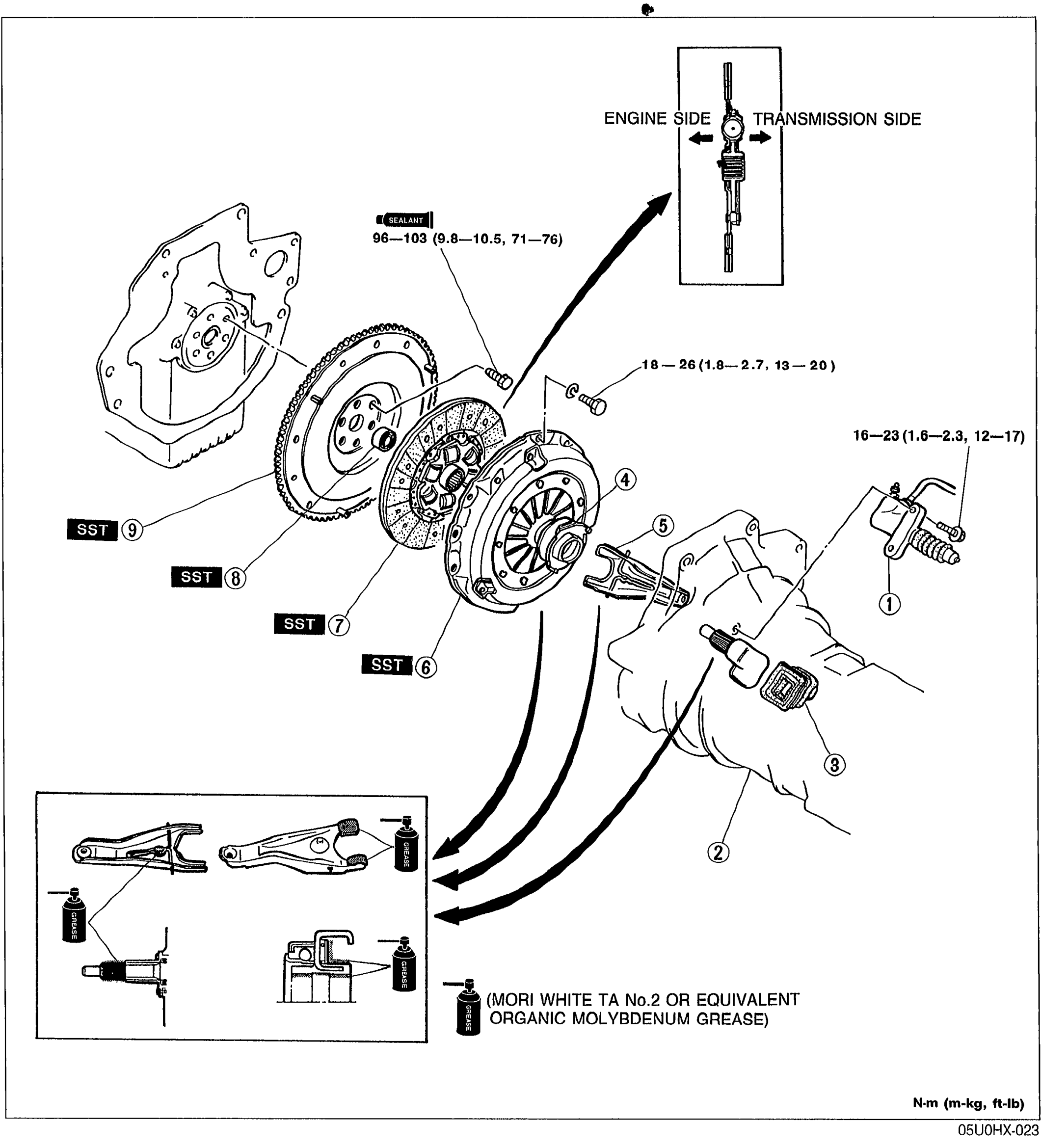
CLUTCH UNIT
H-15Exploded view of the clutch unit with nine numbered balloons: clutch release cylinder, transmission, boot, release bearing, release fork, clutch cover, clutch disc, pilot bearing, flywheel. Inset at top right shows the clutch disc orientation ('ENGINE SIDE' ↔ 'TRANSMISSION SIDE'). Inset at bottom left shows the release fork, release bearing and contact points lubricated with 'MORI WHITE TA No.2 OR EQUIVALENT ORGANIC MOLYBDENUM GREASE'. Torque labels: flywheel bolts 96—103 N·m (9.8—10.5, 71—76), clutch cover bolts 18—26 N·m (1.8—2.7, 13—20), release cylinder bolts 16—23 N·m (1.6—2.3, 12—17). 'SST' tags next to parts 6, 7, 8 and 9.
Manual Transmission
J16 diagrams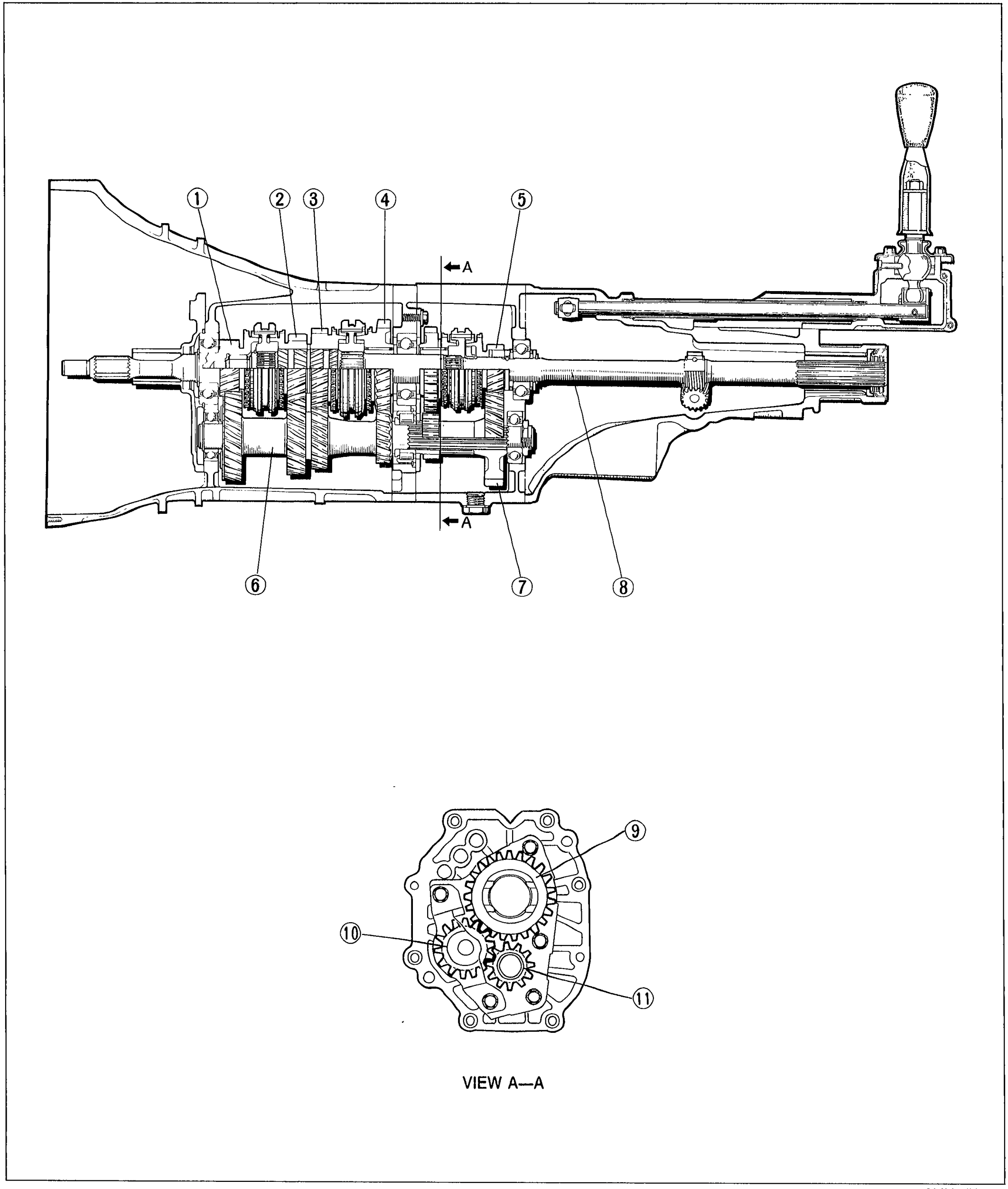
OUTLINE — STRUCTURAL VIEW
J-4Longitudinal cross-section of the M-type 5-speed transmission case showing the main drive gear, mainshaft, countershaft, and gear cluster with shift lever at upper right. Numbered callouts 1-8 identify gears along the top (1-5) and bottom (6-8). Section line A-A through the rear of the gear set. Lower inset is the View A-A cross-section showing reverse idler arrangement with callouts 9-11.
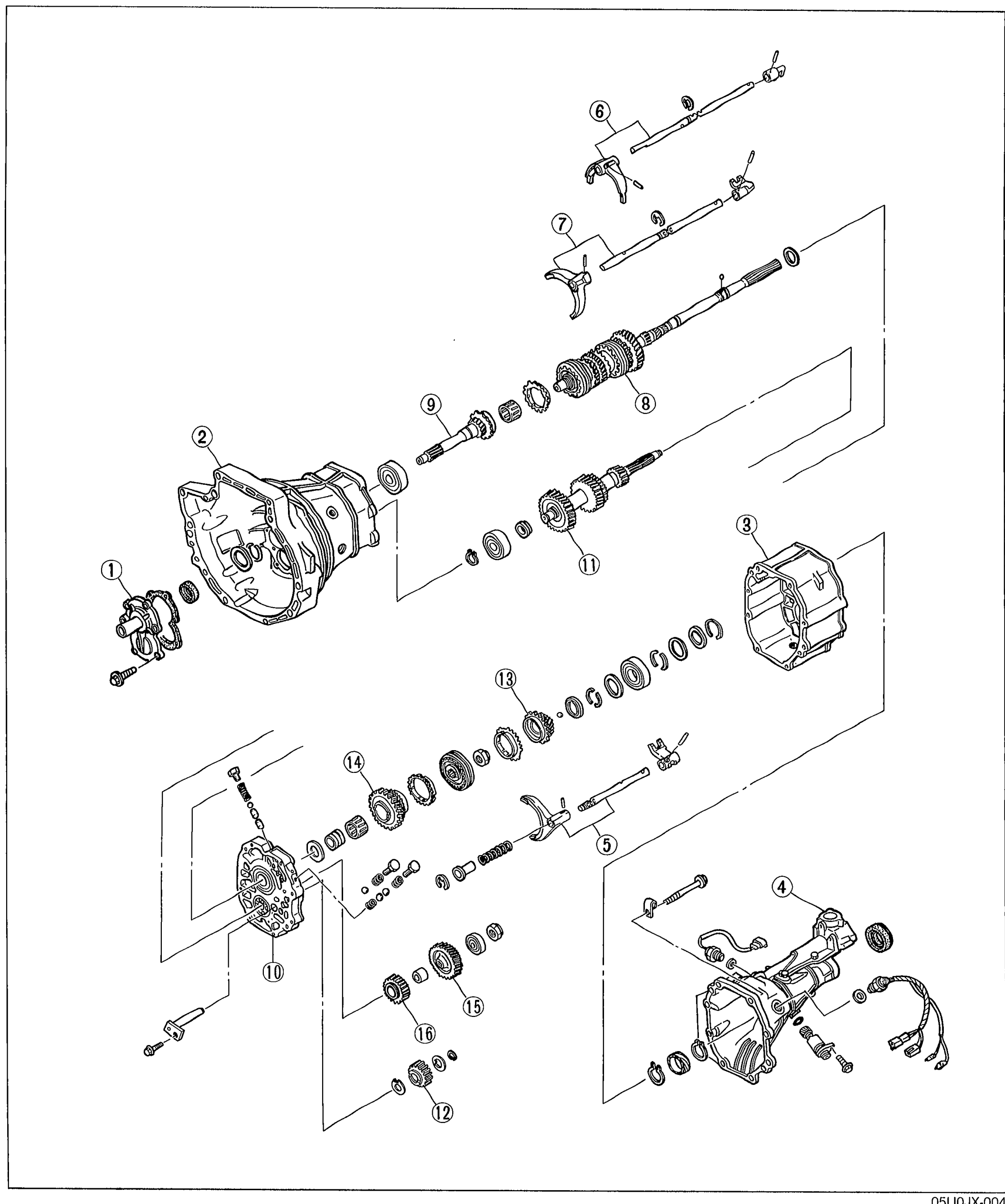
OUTLINE — COMPONENTS
J-5Full exploded view of the M-type 5-speed manual transmission components, showing the transmission case, intermediate housing, extension housing, front cover, shift forks and rods, mainshaft gear assembly with gears 1st through 5th, bearings, countershaft, and reverse idler gear. 16 numbered balloon callouts identify each component.
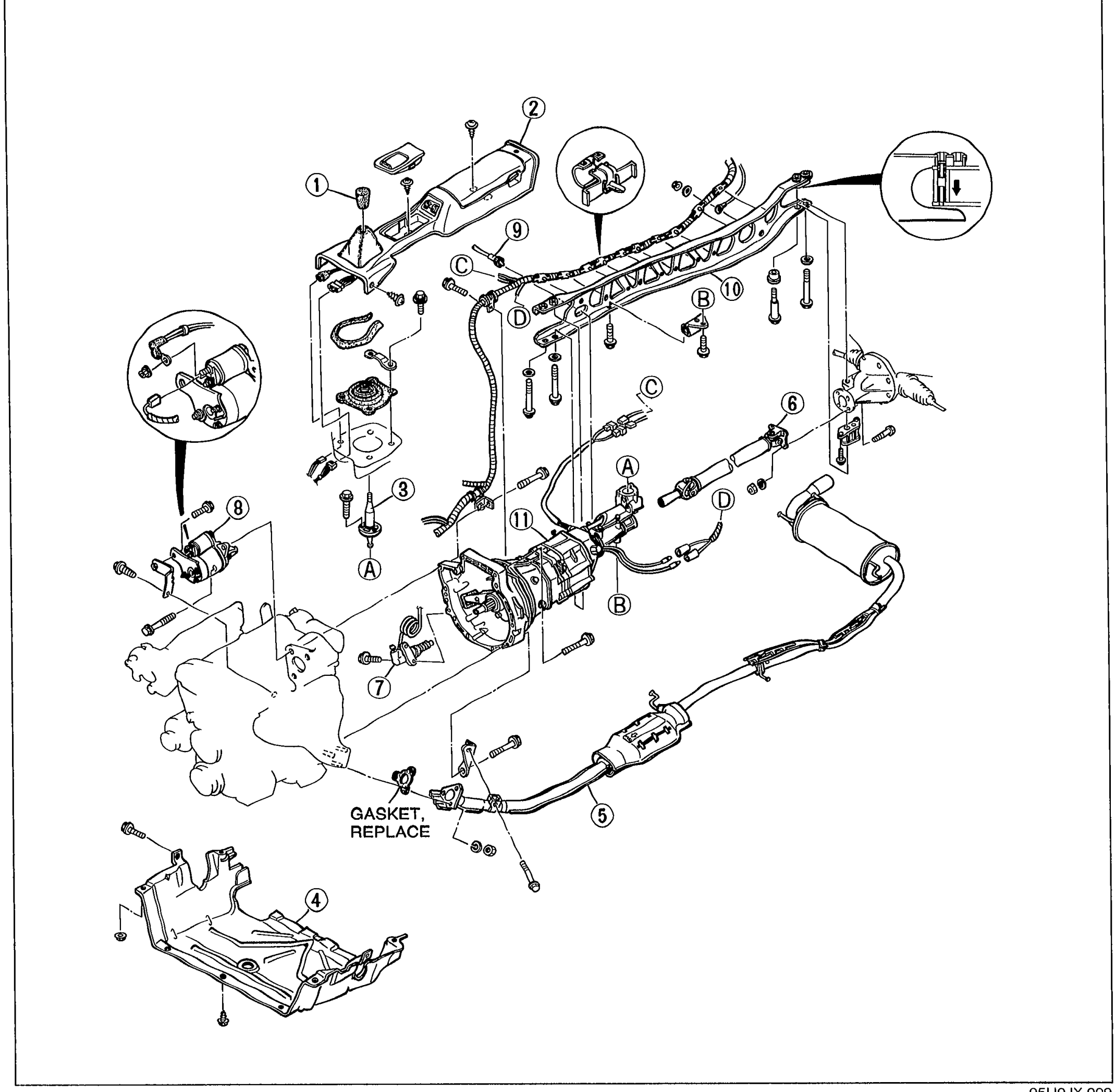
TRANSMISSION - REMOVAL
J-10Exploded view of the manual transmission installation showing the transmission case, propeller shaft, exhaust pipe, power plant frame (PPF), undercover, clutch release cylinder, starter, speedometer cable, shift lever assembly with knob and console, and surrounding bolts/gasket. Eleven numbered balloon callouts identify removal sequence items. A 'GASKET, REPLACE' note is shown at the exhaust pipe joint. Circular detail insets at top illustrate close-up views of fasteners/clamps.
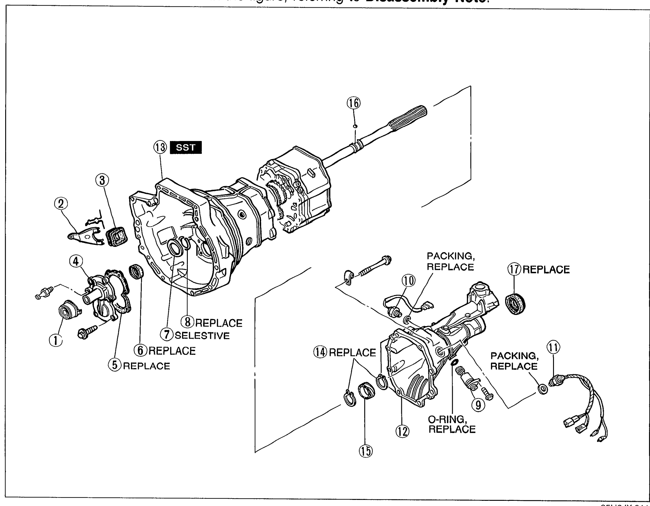
TRANSMISSION - DISASSEMBLY - Housing Components
J-13Exploded view of the manual transmission housing components: clutch housing with release fork and release bearing, front cover, gasket, oil seal (front), adjustment shim, transmission case, extension housing with back-up light switch, neutral switch, speedometer driven gear and drive gear, snap rings, steel ball, packings, O-ring, and oil seal (rear). Seventeen numbered balloons identify each component. Several callouts annotate 'REPLACE', 'PACKING, REPLACE', 'SELECTIVE', 'SST', 'O-RING, REPLACE'.
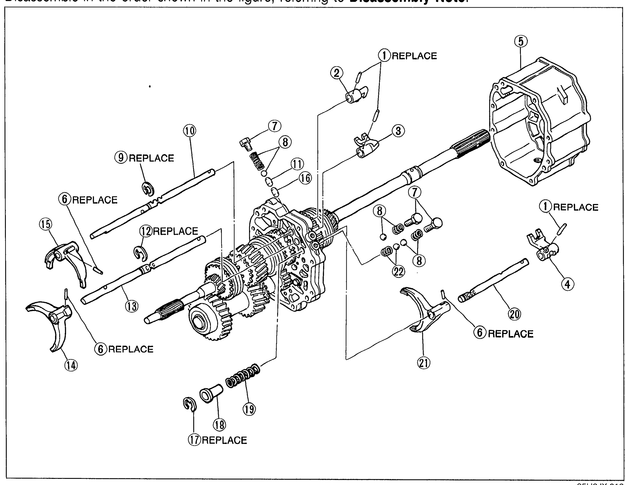
TRANSMISSION — Shift Fork and Shift Rod Parts
J-15Exploded view of transmission shift fork and shift rod assembly with numbered balloon callouts 1-22 indicating each component including roll pins, shift rod ends, intermediate housing, roll pin, cap plug, spring and ball, clip, shift rods, interlock pin, shift forks, and springs.

TRANSMISSION — Mainshaft and Countershaft Parts (parts list + disassembly notes)
J-17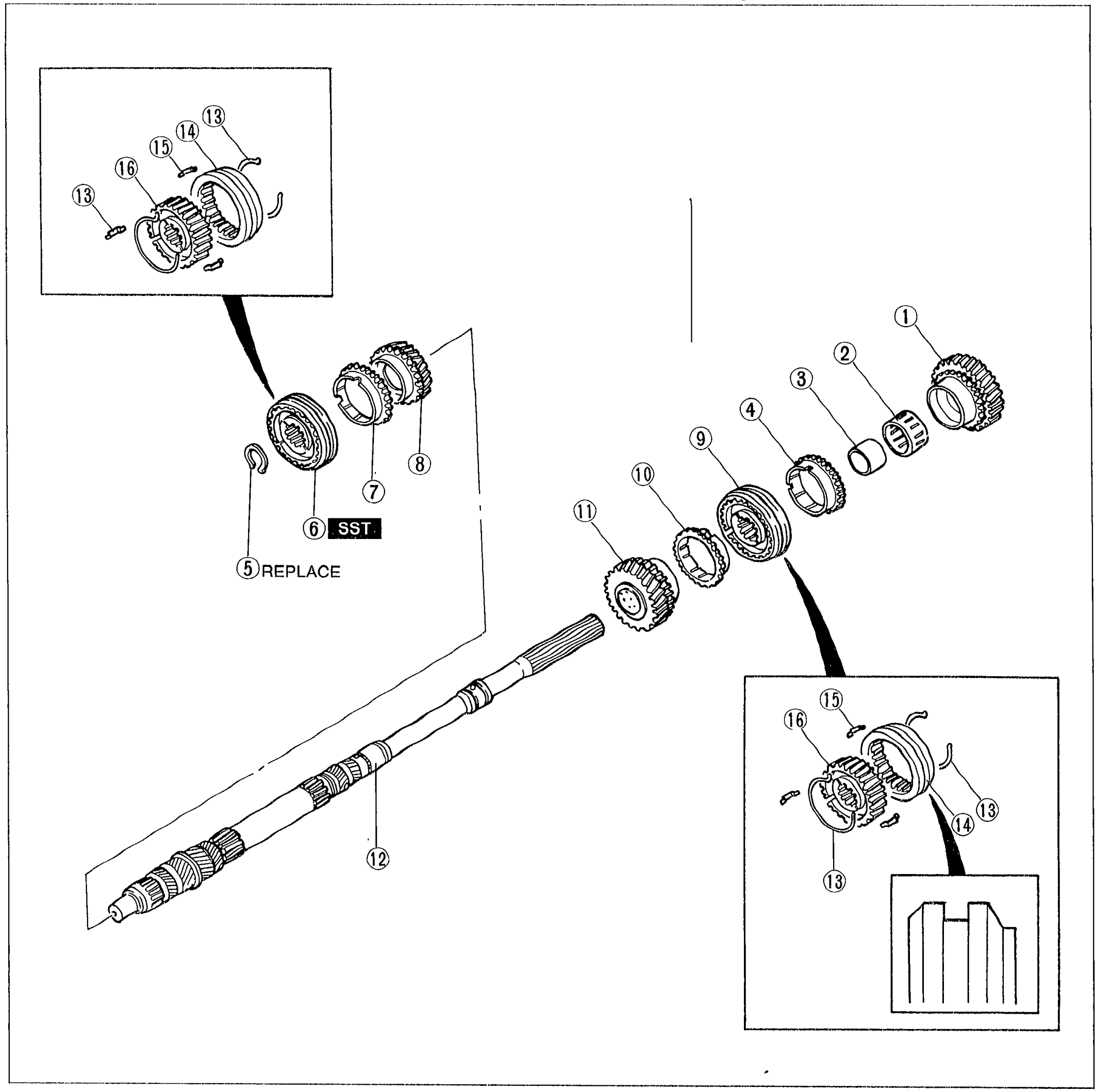
Mainshaft Parts
J-19Exploded view of the transmission mainshaft showing 16 numbered components arranged along the mainshaft axis. Components include 1st gear, needle bearing, inner race, synchronizer rings (1st, 2nd, 3rd), 3rd gear, clutch hub assemblies (3rd/4th and 1st/2nd), snap ring, mainshaft, synchronizer key spring, clutch hub sleeve, synchronizer key, and clutch hub. Two callout magnifications at upper-left and lower-right show clutch hub assembly detail with parts 13-16 (synchronizer key, key spring, hub sleeve, clutch hub). Callout 6 is marked SST and callout 5 is marked REPLACE.
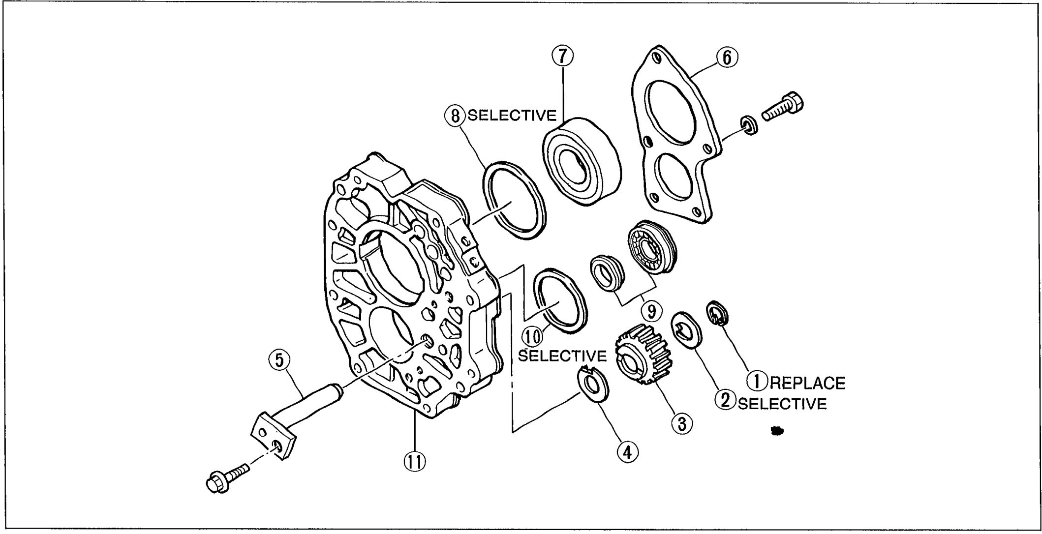
Disassembly note / Bearing Housing Parts
J-20Exploded view of bearing housing assembly showing 11 numbered components: snap ring, adjustment washer, reverse idler gear, thrust washer, reverse idler gear shaft, bearing cover (with bolts), mainshaft front bearing, adjustment shim (SELECTIVE), countershaft center bearing, adjustment shim (SELECTIVE), and bearing housing. Callouts 2, 8, and 10 are labeled SELECTIVE; callout 1 is labeled REPLACE.
Extension Housing Parts
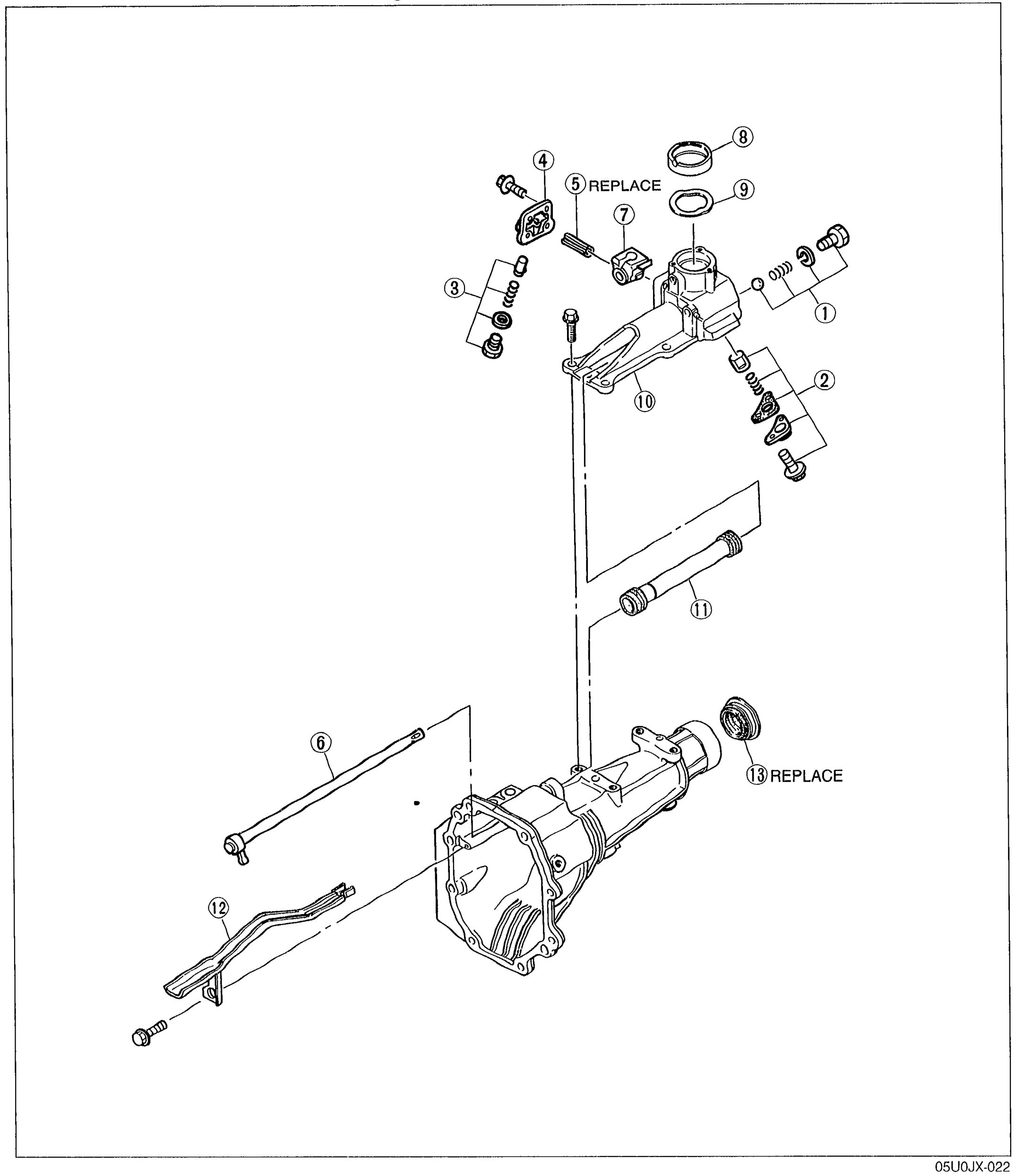
J-22Exploded view of the transmission extension housing showing 13 numbered components: steel ball/spring/spring cap, select-lock spindle assembly, plug-spring-pushpin, blind cover, roll pin, control lever, control lever end, change bushing, wave washer, change control case, rod cover, oil passage, and oil seal. Callouts 5 and 13 are labeled REPLACE.
Extension Housing Parts
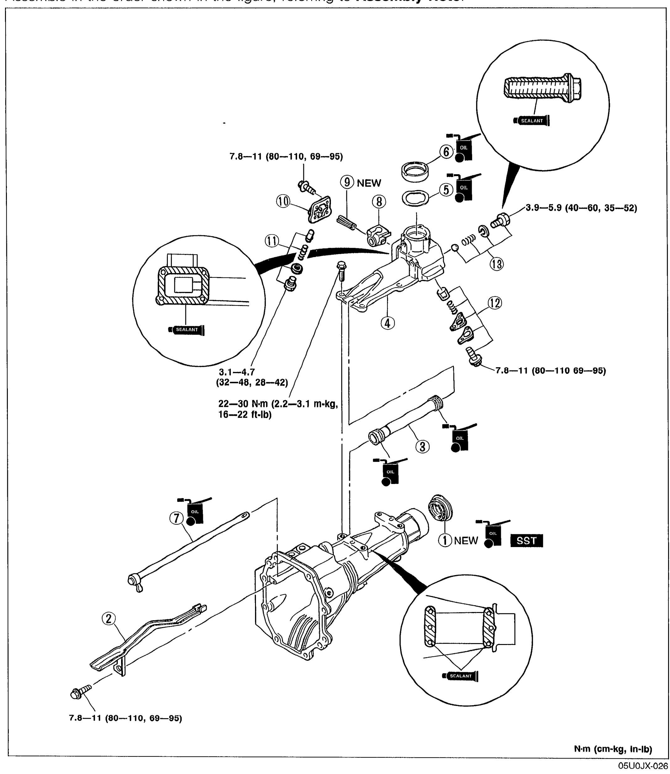
J-27Exploded view of the extension housing assembly showing all 13 numbered components with tightening torque callouts. Includes oil seal (1) with NEW marker and SST callout, oil passage (2), rod cover (3), change control case (4), wave washer (5), change bushing (6), control lever (7), control lever end (8), roll pin (9) with NEW marker, blind cover (10), plug, spring and pushpin (11), select-lock spindle, spring, and spring cap (12), steel ball, spring, and spring cap (13). Sealant application points are shown in callout bubbles. Torque specs: 7.8-11 (80-110, 69-95), 3.9-5.9 (40-60, 35-52), 3.1-4.7 (32-48, 28-42), 22-30 N·m (2.2-3.1 m-kg, 16-22 ft-lb), 7.8-11 (80-110 69-95).
Bearing Housing Parts
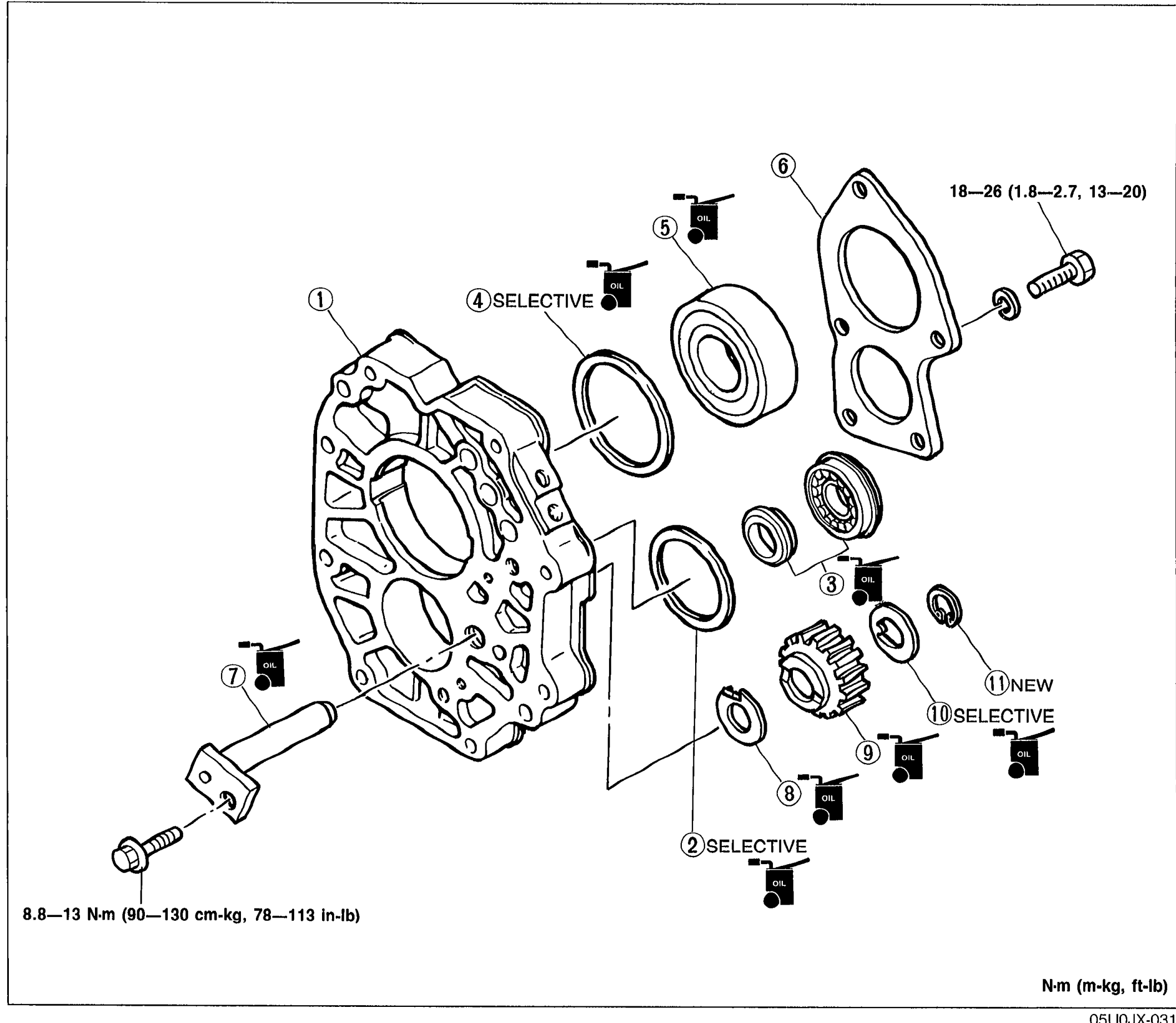
J-29Exploded view of the transmission bearing housing assembly. Shows the bearing housing (1) with adjustment shim (2, SELECTIVE), countershaft center bearing (3), adjustment shim (4, SELECTIVE), mainshaft front bearing (5), bearing cover (6), reverse idler gear shaft (7), thrust washer (8), reverse idler gear (9), adjustment washer (10, SELECTIVE), and snap ring (11, NEW). Torque specs shown: 18—26 N·m (1.8—2.7 m-kg, 13—20 ft-lb) at the bearing cover bolts; 8.8—13 N·m (90—130 cm-kg, 78—113 in-lb) at the reverse idler gear shaft bolt.
Mainshaft Parts
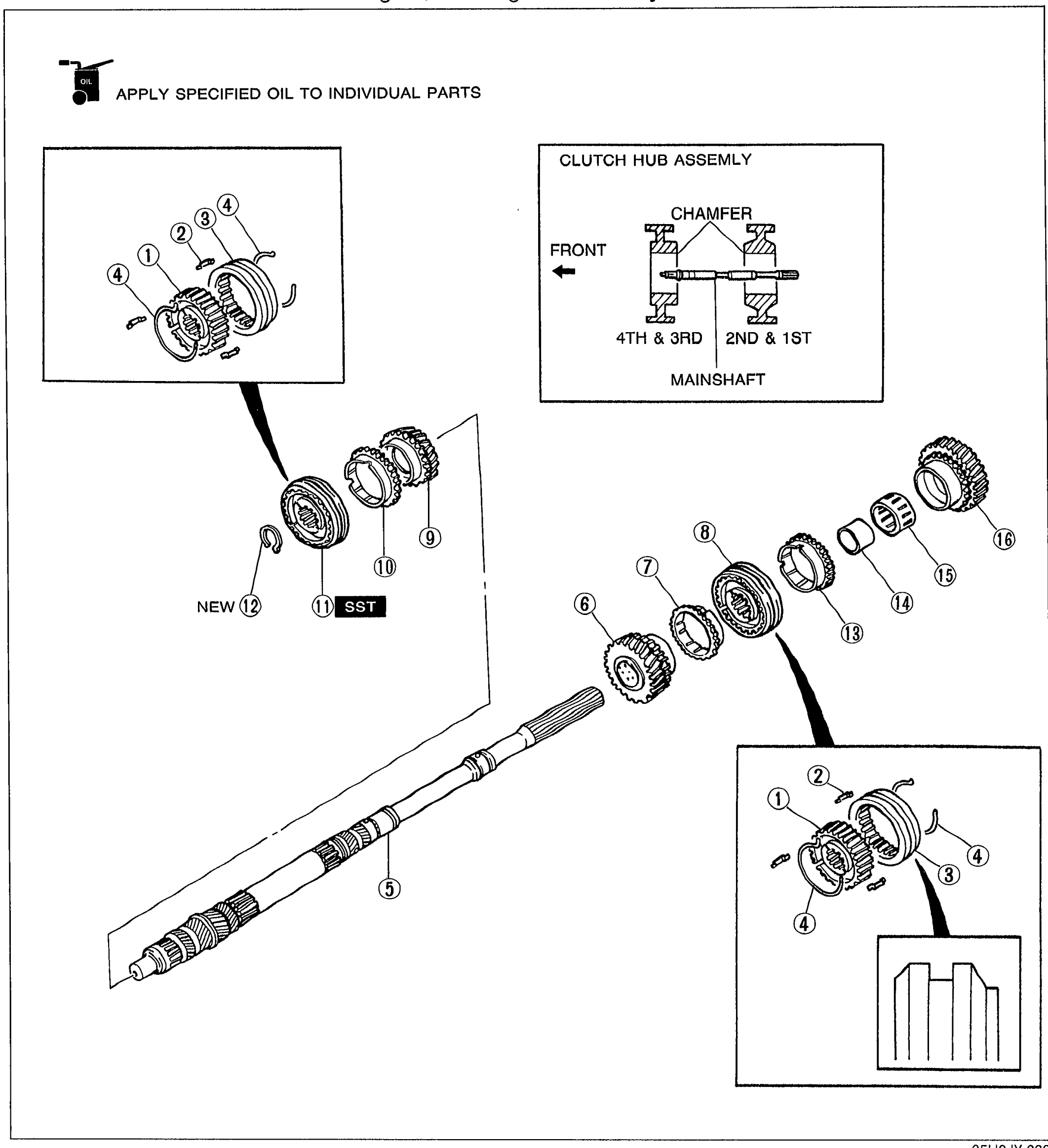
J-31Exploded view of the transmission mainshaft and synchronizer assemblies. The mainshaft (5) runs through the figure with clutch hub (1), synchronizer key (2), clutch hub sleeve (3), synchronizer key spring (4), 2nd gear (6), synchronizer ring (7), clutch hub assembly 1st/2nd (8), 3rd gear (9), synchronizer ring 3rd (10), clutch hub assembly 3rd/4th (11), snap ring (12, NEW), synchronizer ring (13), inner race (14), needle bearing (15), and 1st gear (16). Detail at top shows the CLUTCH HUB ASSEMBLY orientation with CHAMFER, FRONT indicator, and labels for 4TH & 3RD and 2ND & 1ST sides relative to MAINSHAFT. An oil-can icon notes 'APPLY SPECIFIED OIL TO INDIVIDUAL PARTS'. An SST tag is shown next to part 11.

Mainshaft and Countershaft Parts (continued)
J-35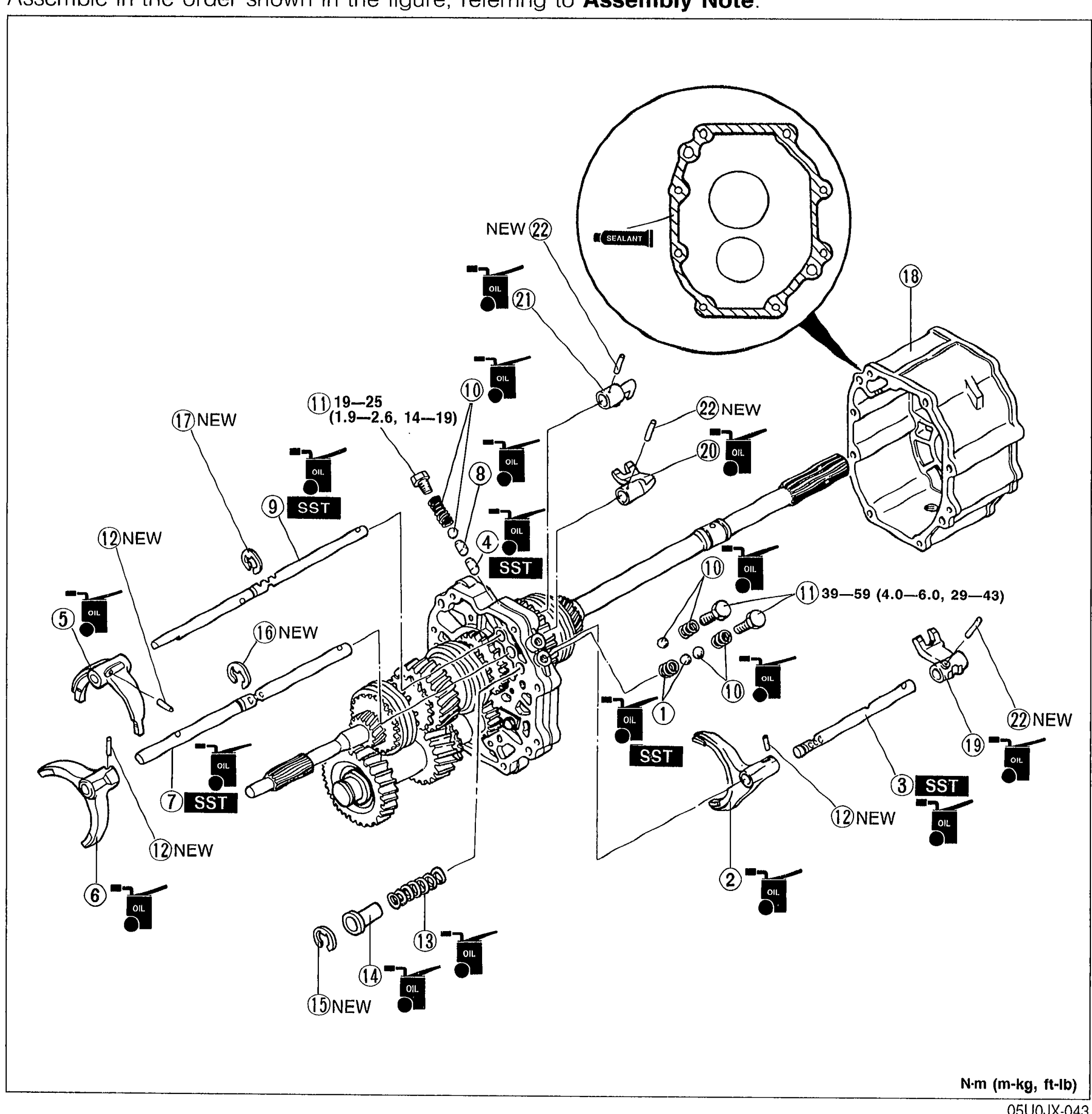
Shift Fork and Shift Rod Parts
J-38Exploded view of shift fork and shift rod assembly showing 22 numbered parts with balloon callouts. Includes shift forks (2, 5, 6) marked SST, shift rods (3, 7), interlock pin (4), springs and balls, multiple NEW markers (10, 12, 15, 16, 17, 22), and the intermediate housing (18) at top right with sealant application detail. Torque callouts: 19-25 (1.9-2.6, 14-19) for item 11, and 39-59 (4.0-6.0, 29-43) for item 1.

Transmission Case Parts (continued) / Assembly note
J-43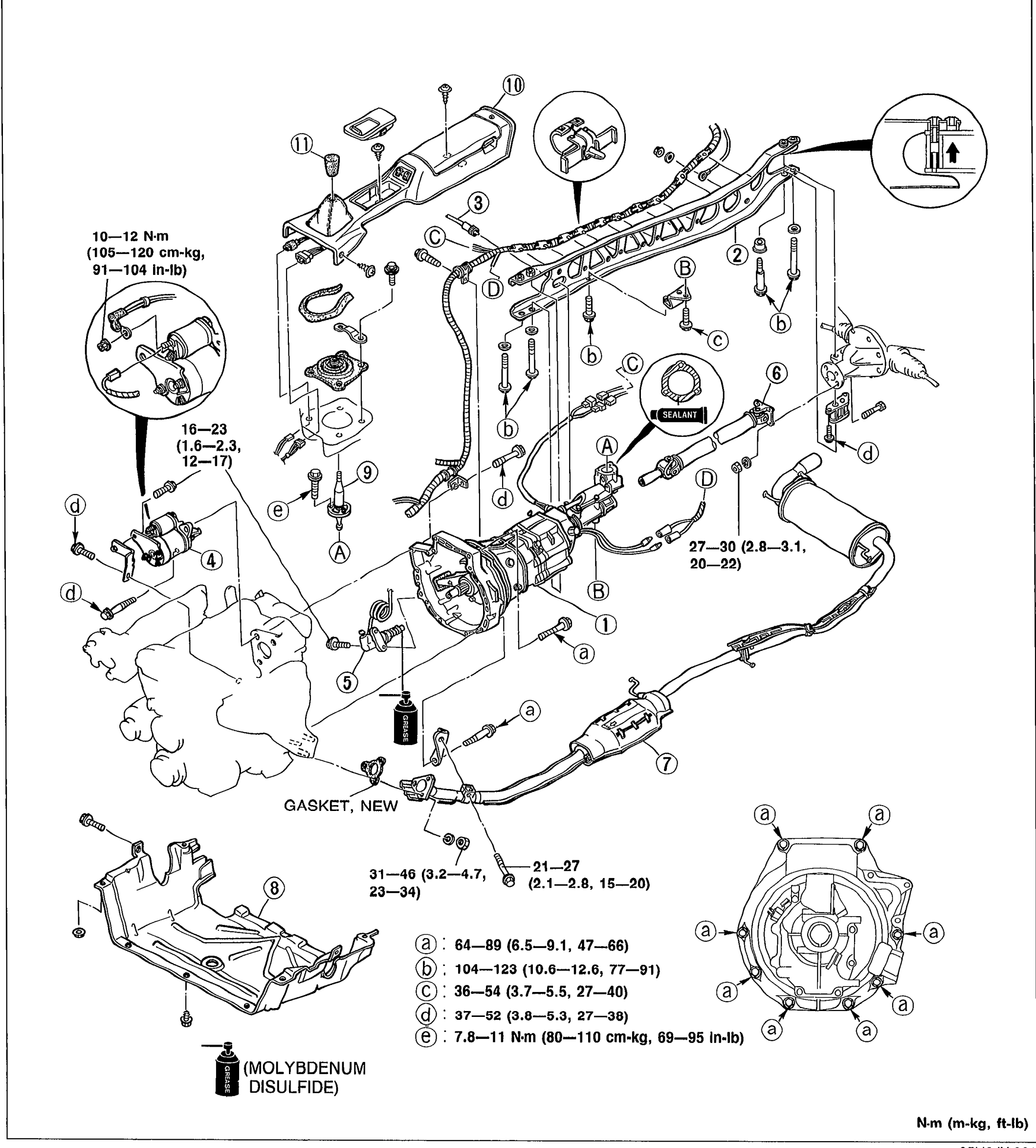
TRANSMISSION - INSTALLATION
J-45Exploded view of transmission installation showing the transmission, power plant frame (PPF), speedometer cable, starter, clutch release cylinder, propeller shaft, exhaust pipe, undercover, shift lever, rear console, and shift lever knob. Numbered balloon callouts 1-11 identify components; lettered callouts a–e indicate torque specifications. A 'GASKET, NEW' annotation and a '(MOLYBDENUM DISULFIDE)' grease note appear with arrows to application points.
Front and Rear Axles
M9 diagrams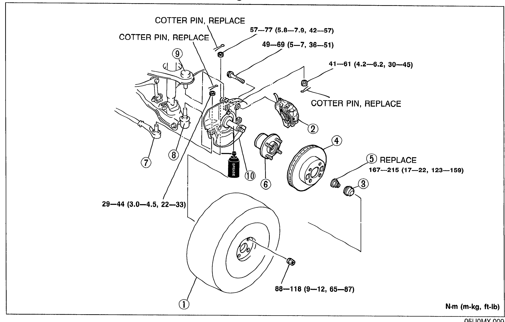
FRONT AXLE
M-5Exploded view of the MX-5 front axle showing the front wheel, brake caliper assembly, hub cap, disc plate, locknut, front wheel hub assembly, tie-rod end, lower arm, upper arm and dust cover/knuckle spindle. Numbered balloon callouts 1–10 identify components. COTTER PIN, REPLACE labels mark cotter-pin replacement points and a REPLACE flag marks callout 5 (locknut). Tightening torque values shown next to fasteners.
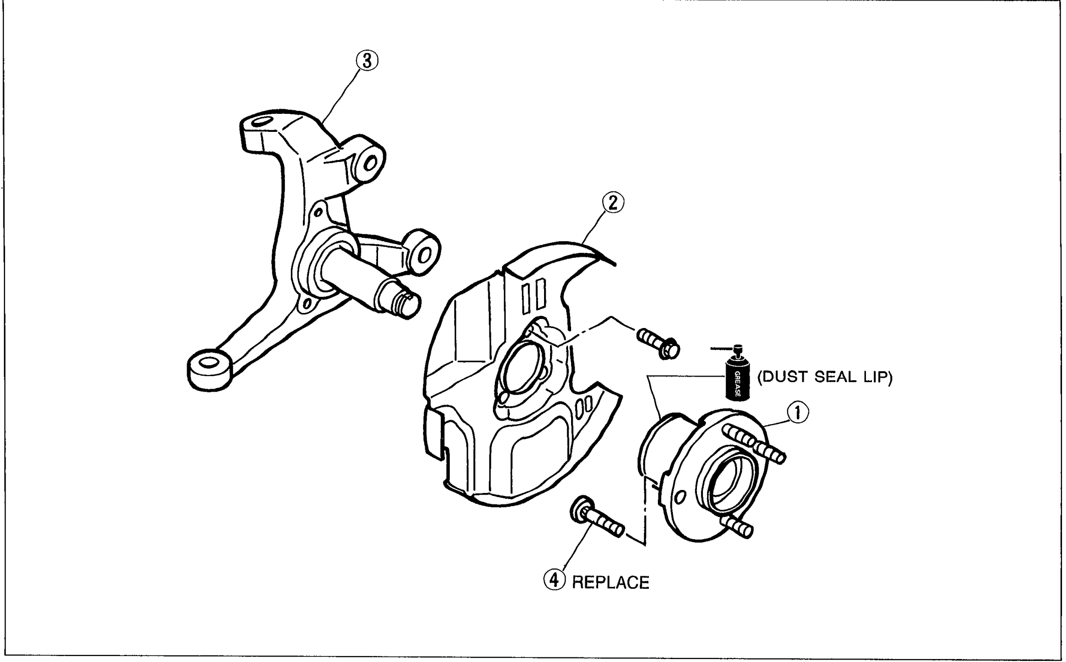
FRONT AXLE — Disassembly / Inspection / Assembly
M-8Exploded view of front axle hub assembly. Shows knuckle spindle (callout 3) at upper left, dust cover (callout 2) center with arrow indicating DUST SEAL LIP, front wheel hub assembly (callout 1) at right, and two hub bolts (callout 4, marked REPLACE) shown being inserted into the hub.
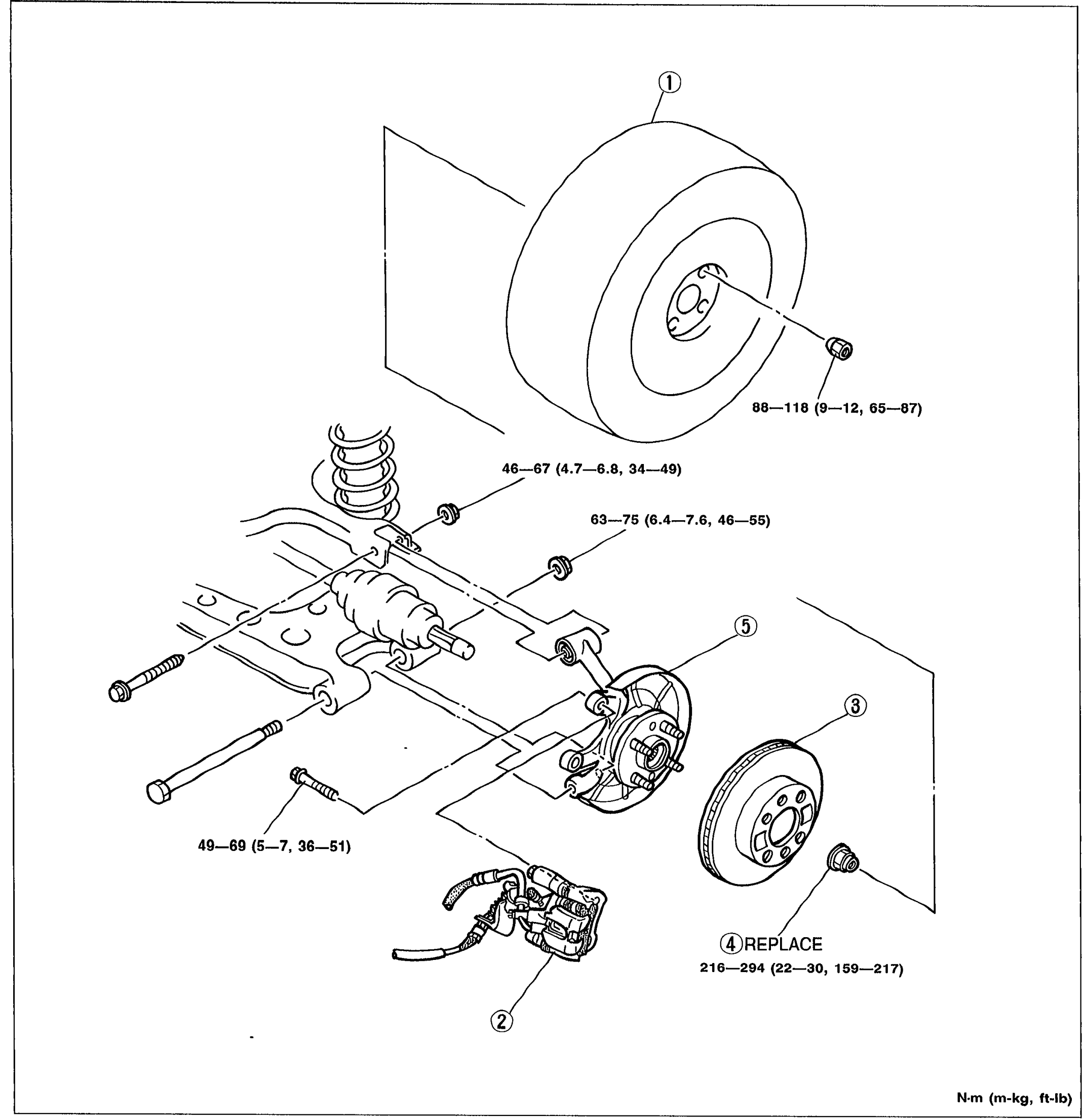
REAR AXLE — Disc Brake Type — Inspection / Removal / Installation
M-10Exploded view of rear axle, disc brake type. Shows rear wheel (callout 1) at upper right, brake caliper assembly (callout 2) at bottom center, disc plate (callout 3) at right, locknut (callout 4, marked REPLACE) at right with torque spec, and knuckle/wheel hub/dust cover (callout 5) at center right. Coil spring and trailing arm shown at left. Torque specs shown for multiple fasteners in N·m (m-kg, ft-lb).
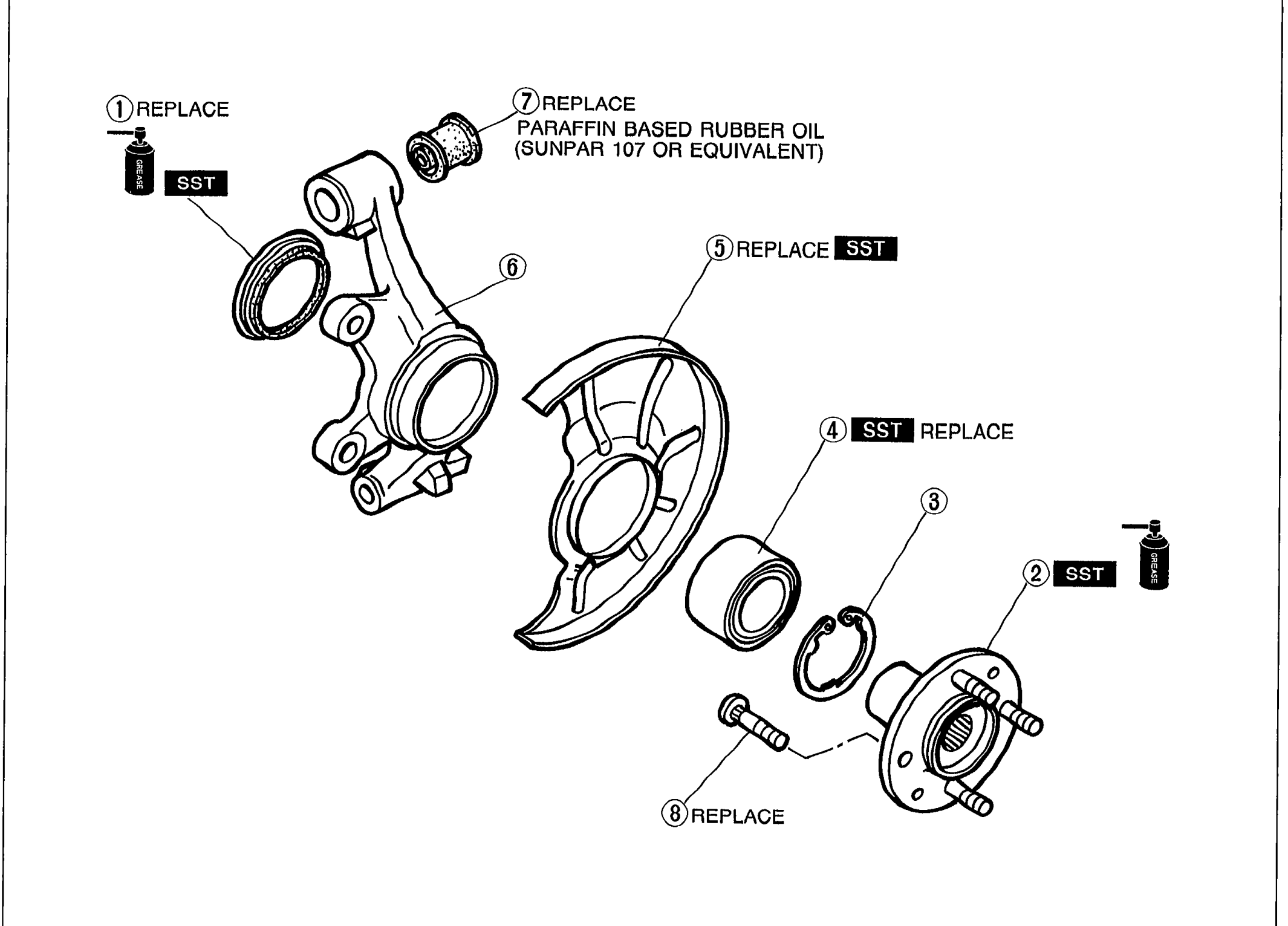
REAR AXLE
M-12Exploded view of the rear axle hub assembly showing numbered callouts 1-8: oil seal, rear wheel hub assembly, retaining ring, wheel bearing, dust cover, knuckle, bushing, and hub bolt. REPLACE and SST tags mark items requiring new parts or special tools. Note '7 REPLACE / PARAFFIN BASED RUBBER OIL (SUNPAR 107 OR EQUIVALENT)' annotates the bushing.
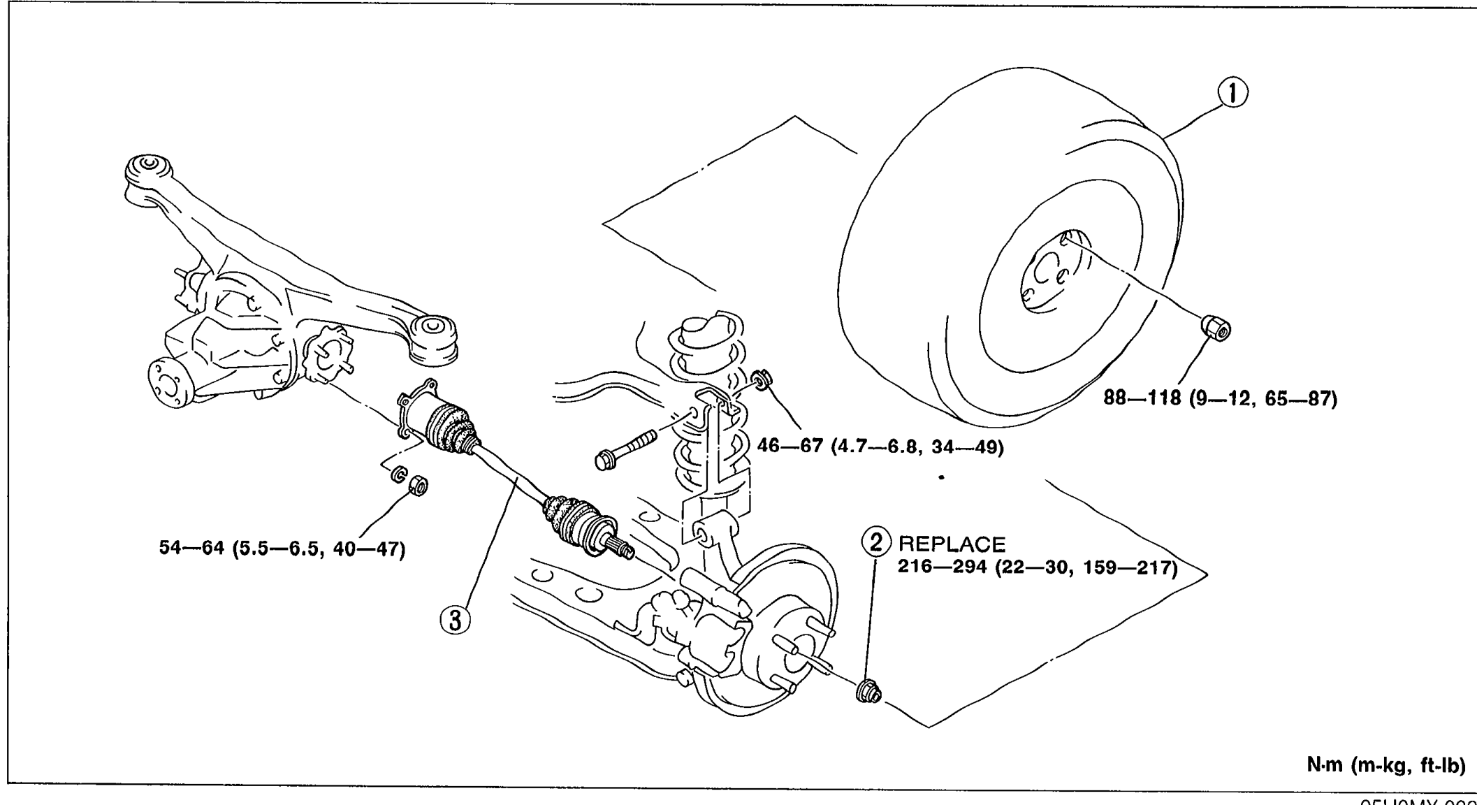
DRIVESHAFT
M-16Exploded view of the rear driveshaft installation showing the rear wheel (1), locknut (2 REPLACE), and driveshaft (3). Tightening torques labeled on the figure: 88—118 N·m (9—12 m-kg, 65—87 ft-lb) at the rear wheel; 46—67 N·m (4.7—6.8 m-kg, 34—49 ft-lb) at an intermediate fastener; 54—64 N·m (5.5—6.5 m-kg, 40—47 ft-lb) at the inner driveshaft end; 216—294 N·m (22—30 m-kg, 159—217 ft-lb) at the locknut.
DRIVESHAFT
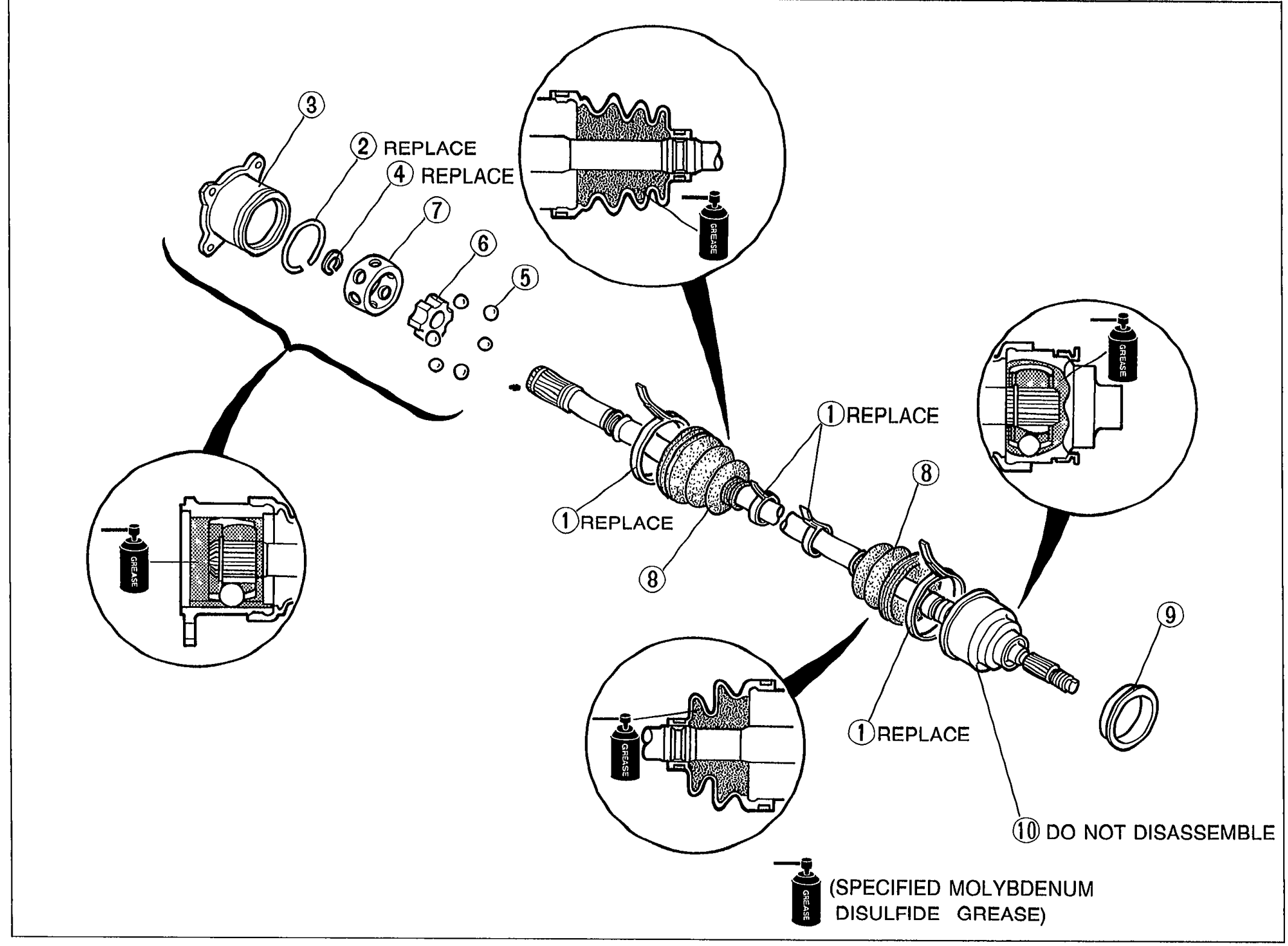
M-18Large exploded view of the driveshaft assembly (double-offset joint) with numbered callouts 1-10: boot bands, clip, outer ring, snap ring, balls, inner ring, cage, boots, dust cover, and shaft and ball joint assembly. REPLACE tags mark new-part items; 'DO NOT DISASSEMBLE' marks the wheel-side ball joint. A grease symbol annotated 'SPECIFIED MOLYBDENUM DISULFIDE GREASE' indicates lubrication points.
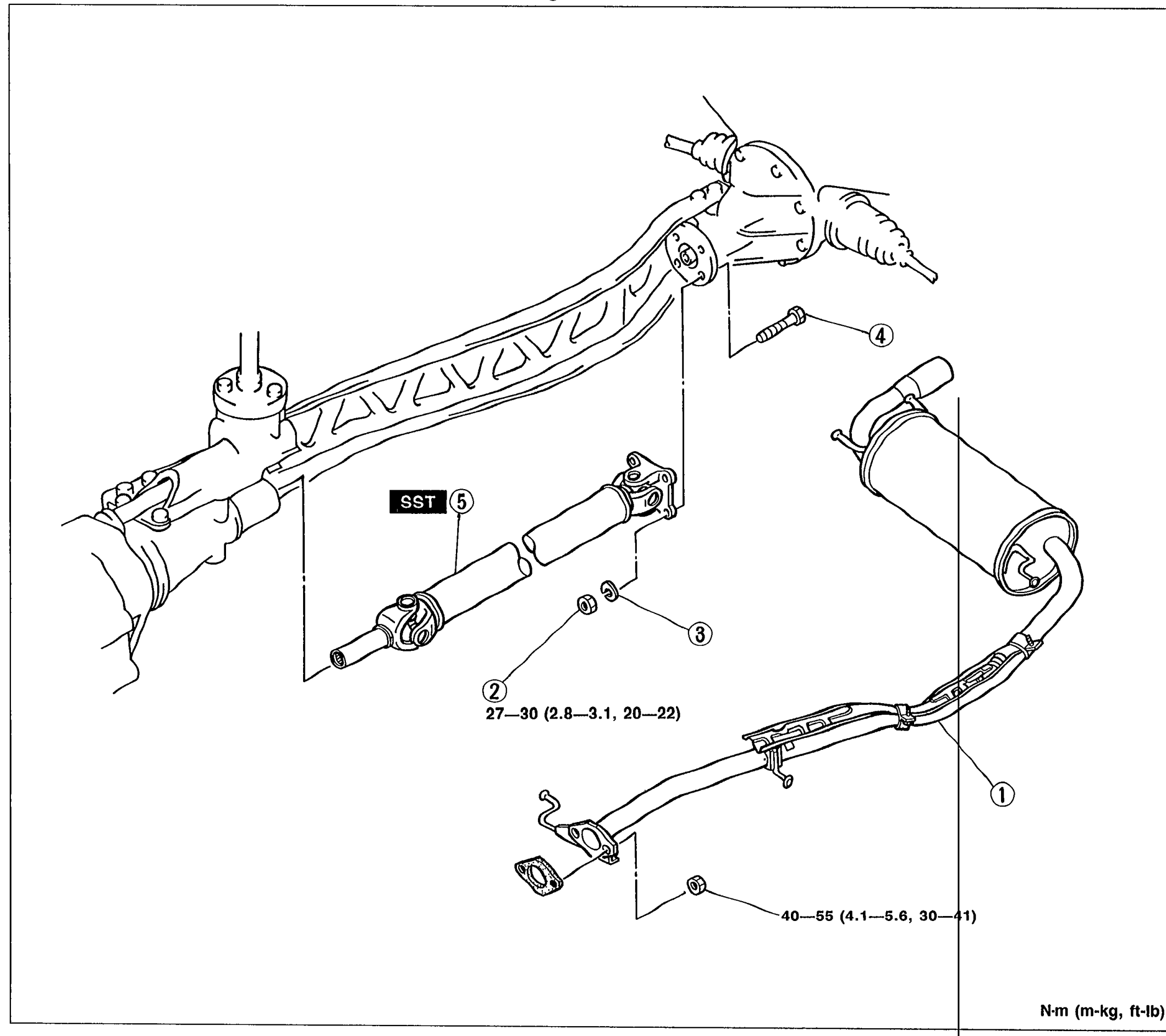
DIFFERENTIAL
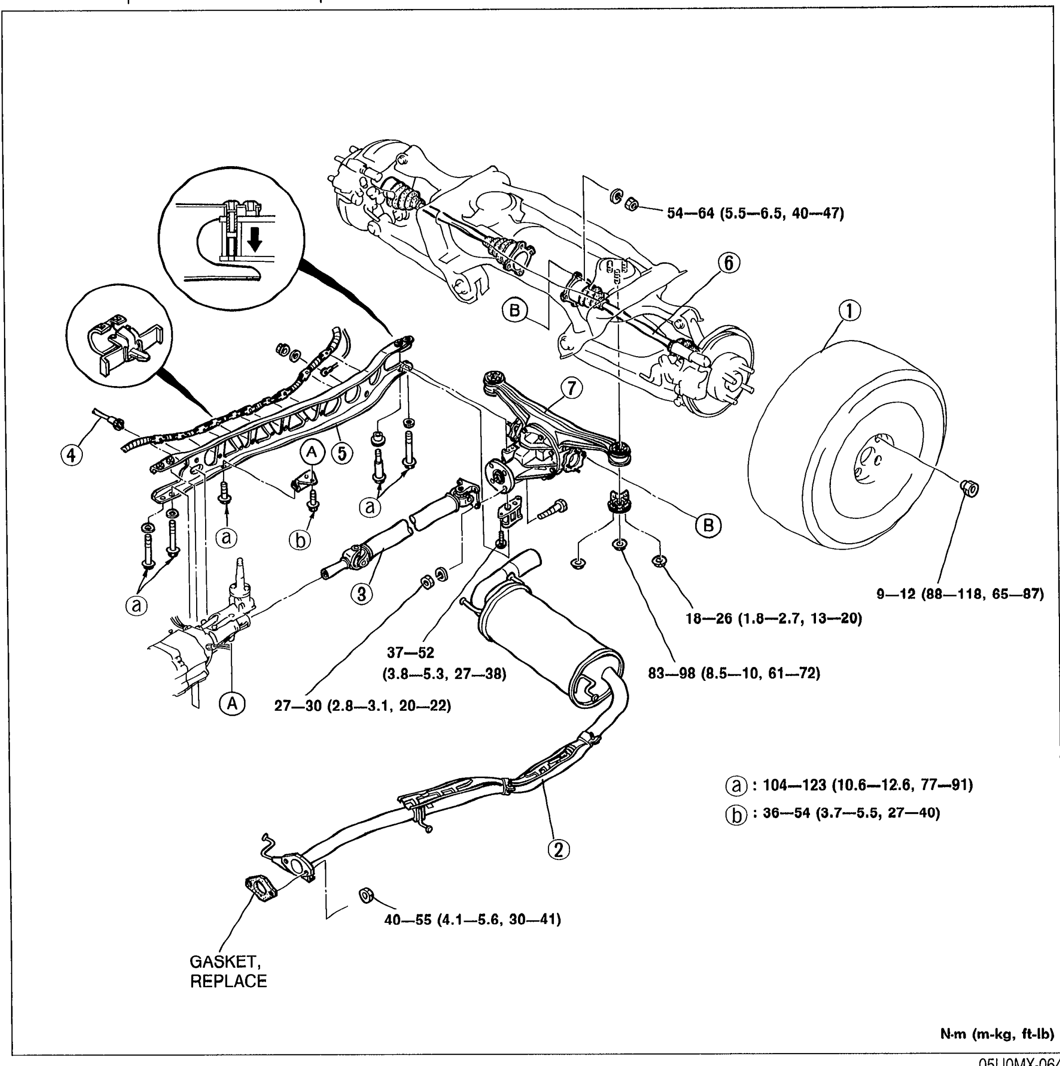
M-27Exploded view of the rear differential, propeller shaft, power plant frame (PPF), exhaust pipe, and rear axle assembly with numbered balloon callouts 1-7 and lettered torque-spec callouts (a, b, A, B) corresponding to fastener locations. Tightening torques shown in N·m (m-kg, ft-lb).
DIFFERENTIAL
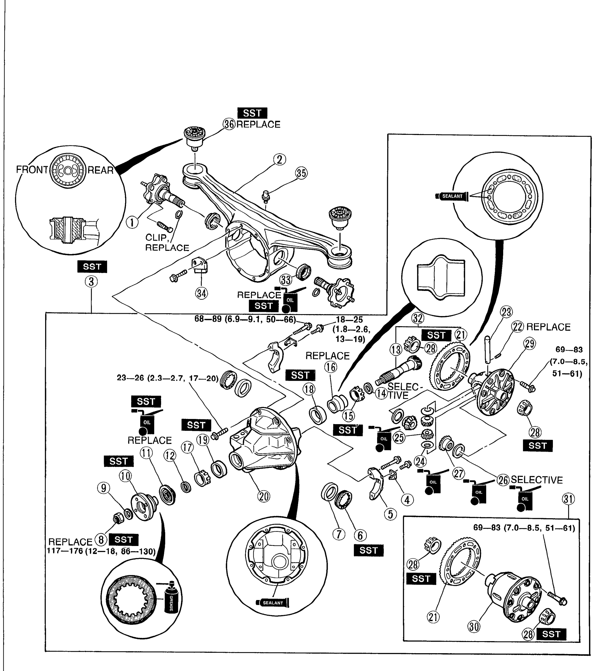
M-32Full-page exploded view of the differential overhaul, with 36 numbered balloon callouts identifying the differential housing, drive gear, ring gear, pinion gear, bearings, oil seals, side gears, pinion shafts, and companion flange. SST, REPLACE, SEALANT, and SELECTIVE labels are placed beside specific callouts. A small FRONT/REAR orientation key with a CLIP/REPLACE label is shown in the upper left. Torque values are written next to certain bolt callouts: 23—26 (2.3—2.7, 17—20), 68—89 (6.9—9.1, 50—66), 18—25 (1.8—2.6, 13—19), 69—83 (7.0—8.5, 51—61), and 117—176 (12—18, 86—130).

DIFFERENTIAL
M-33Page-level reference label for the parts-diagram legend continued from page M-32.
Steering System
N6 diagrams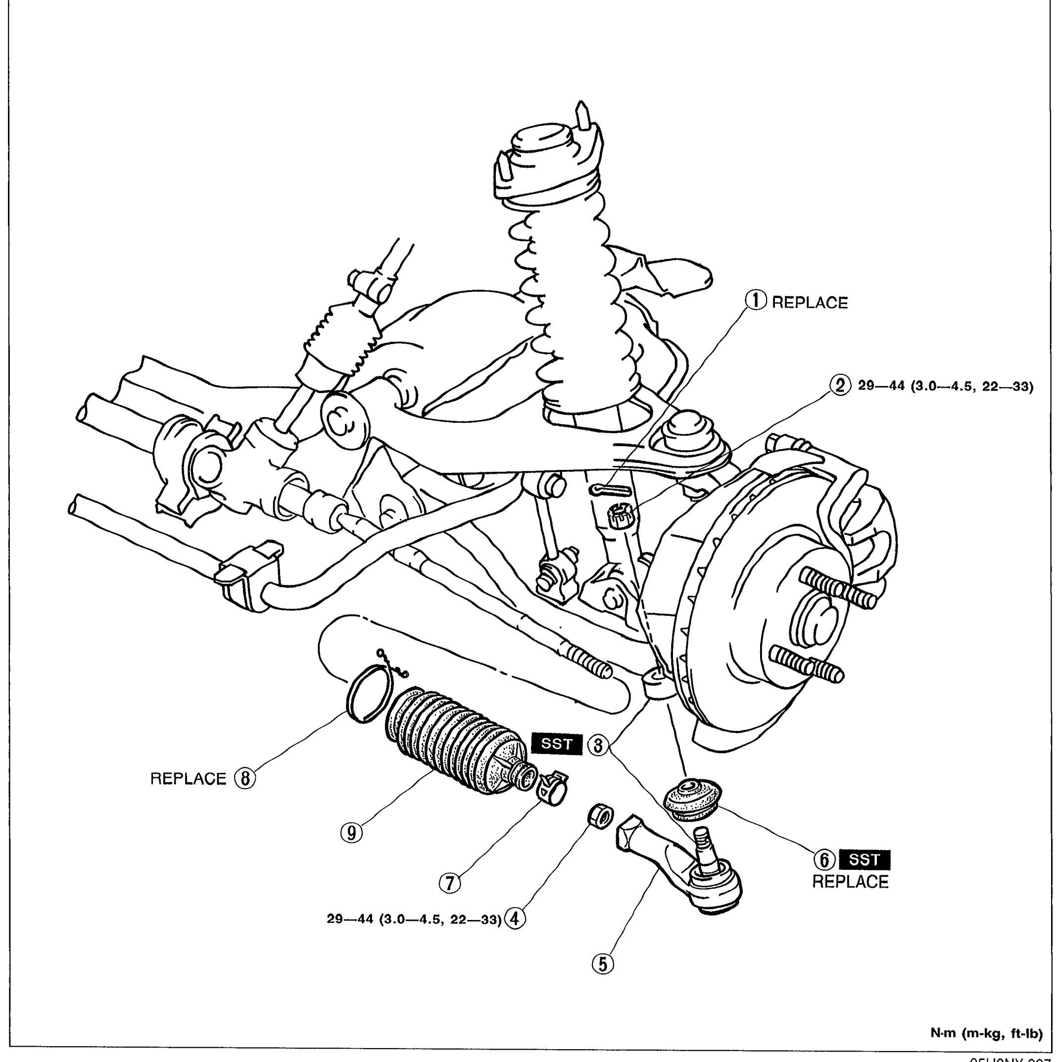
MANUAL STEERING
N-6Exploded view of the steering boot and tie-rod end assembly attached to the steering knuckle/front suspension. Shows the strut/spring, brake rotor, steering knuckle, and the tie-rod with boot, locknut, and ball-end. Numbered balloon callouts 1-9 identify components for replacement/disassembly. Notes: '1 REPLACE' label near top, '2 29—44 (3.0—4.5, 22—33)' torque for nut, '3 SST' indicating SST use at one point, '4 29—44 (3.0—4.5, 22—33)' torque for tie-rod, '6 SST REPLACE', '8 REPLACE' near boot, and 'N·m (m-kg, ft-lb)' units legend bottom-right.
MANUAL STEERING
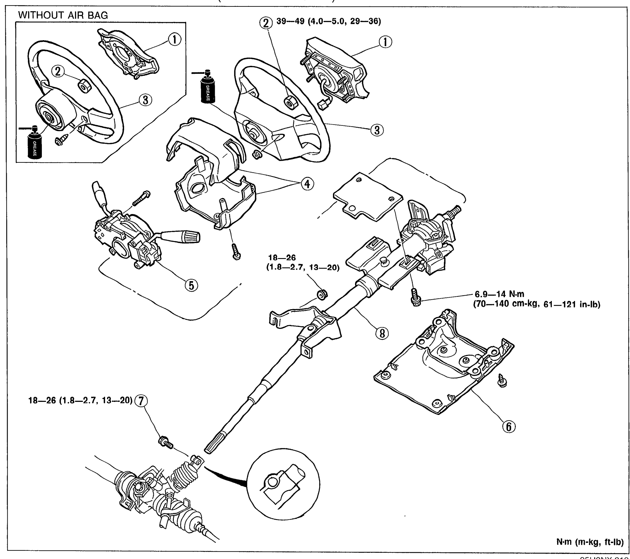
N-9Exploded view of the steering wheel and column assembly (WITHOUT AIR BAG version on the left). Shows balloon callouts 1–8 for: air bag module, horn pad, locknut, steering wheel, column cover, lower panel, intermediate shaft bolt, and steering shaft. Torque specifications annotated next to fasteners: 39—49 N·m at the top retaining nut, 18—26 N·m at the upper steering shaft bolt and at the lower shaft bolt (callout 7), and 6.9—14 N·m at the column mounting bracket bolts. A small detail view at the bottom-right shows the intermediate shaft U-joint orientation.
MANUAL STEERING
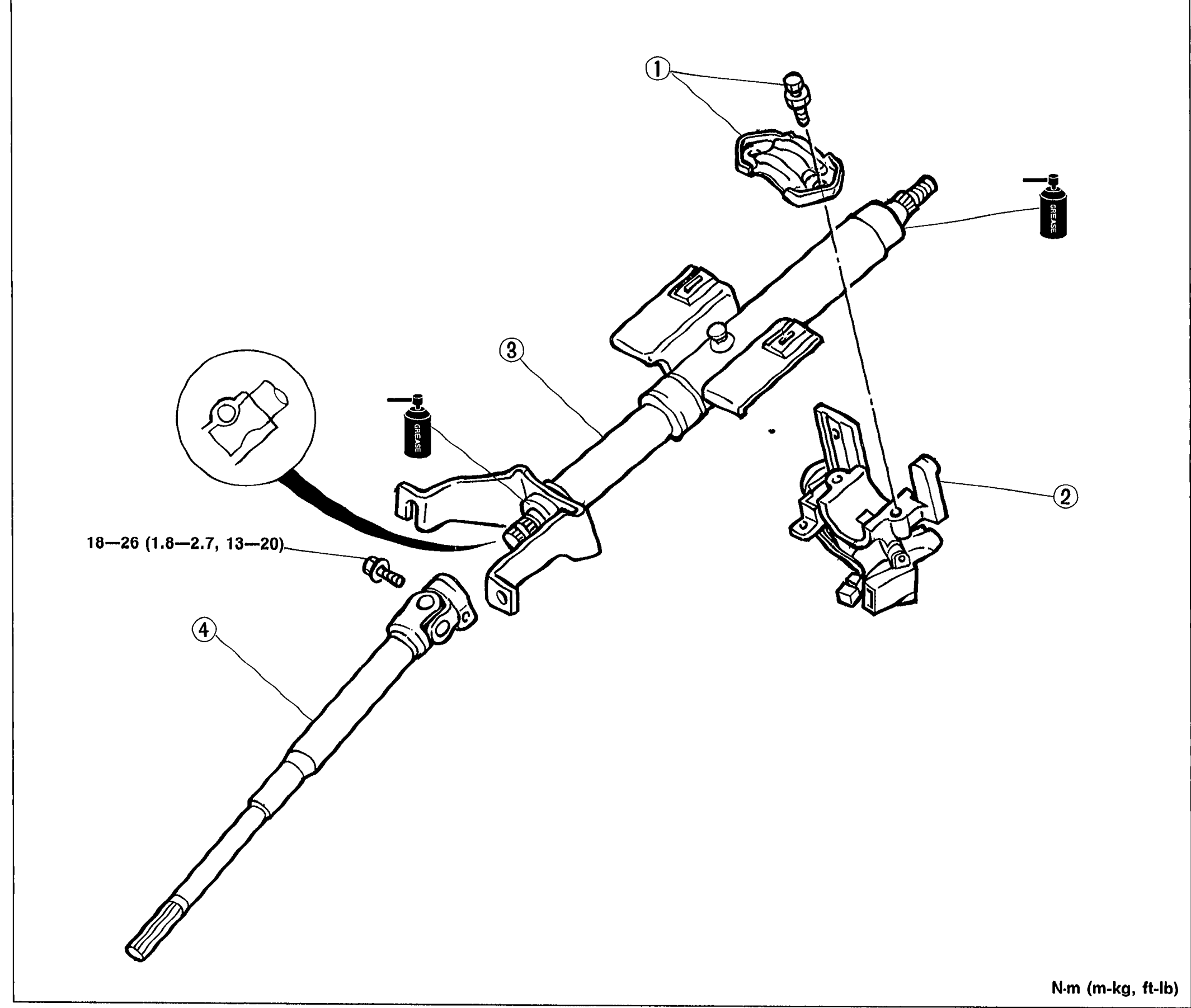
N-10Exploded view of the steering shaft assembly. Shows numbered balloon callouts 1–4 for: steering lock mounting bolts and bracket, steering lock assembly, steering shaft, and intermediate shaft. A detail circle (lower-left) shows U-joint alignment. Torque spec 18—26 N·m (1.8—2.7 m-kg, 13—20 ft-lb) annotated at the intermediate shaft bolt.
MANUAL STEERING
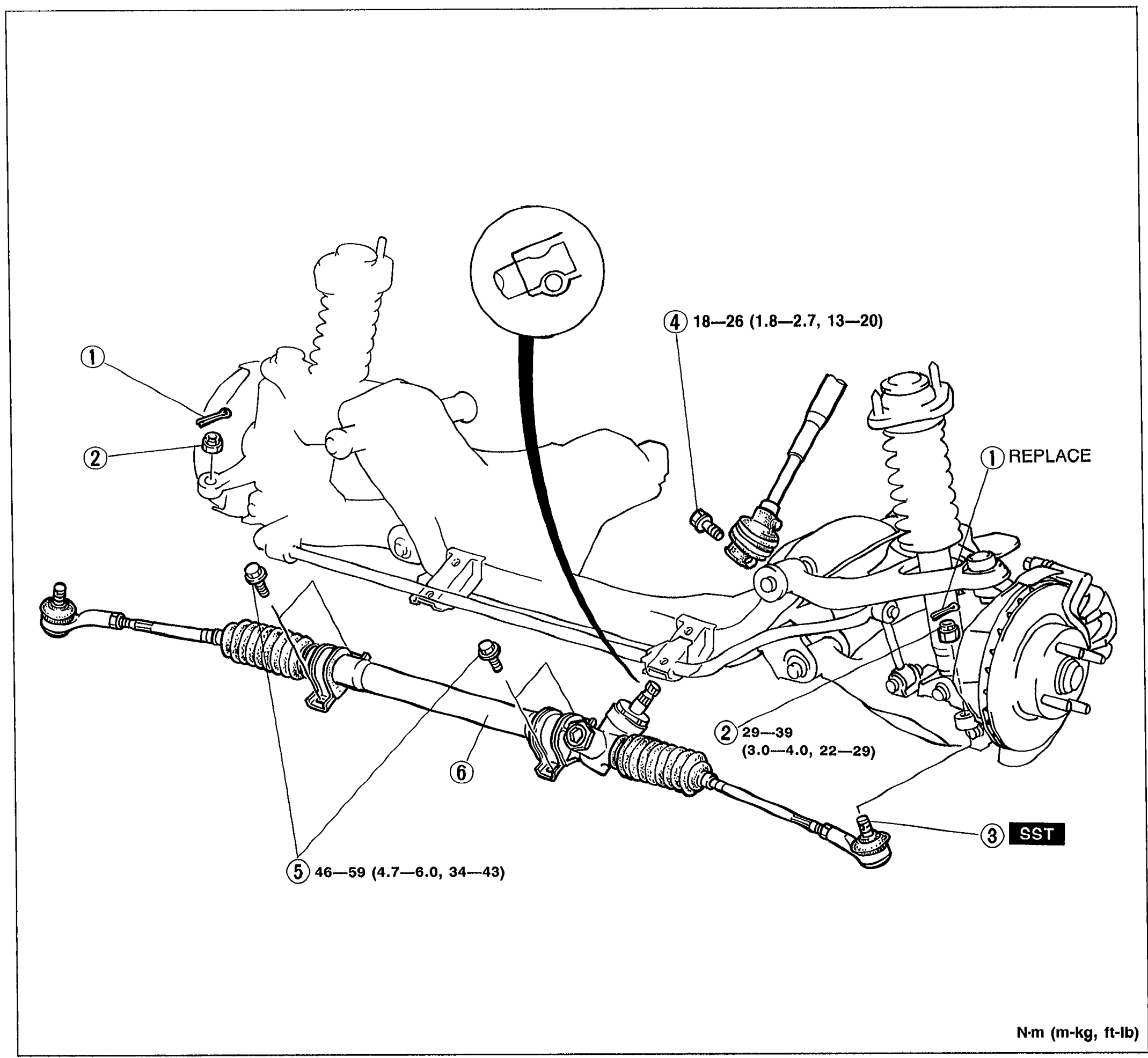
N-12Exploded view of the steering gear and linkage assembly. Shows the rack-and-pinion steering gear, tie-rod ends, ball joints, and steering knuckle with numbered balloon callouts 1–6 for: cotter pin, locknut, tie-rod end, intermediate shaft bolt, mounting bracket bolt, and steering gear and linkage. Torque values are annotated: 18—26 N·m at the intermediate shaft bolt (4), 29—39 N·m at the locknut (2), 46—59 N·m at the mounting bracket bolt (5). 'REPLACE' label near the cotter pin (1). 'SST' label near tie-rod end (3). A detail circle (top) shows the intermediate shaft U-joint alignment.
ENGINE SPEED SENSING POWER STEERING — STEERING GEAR AND LINKAGE
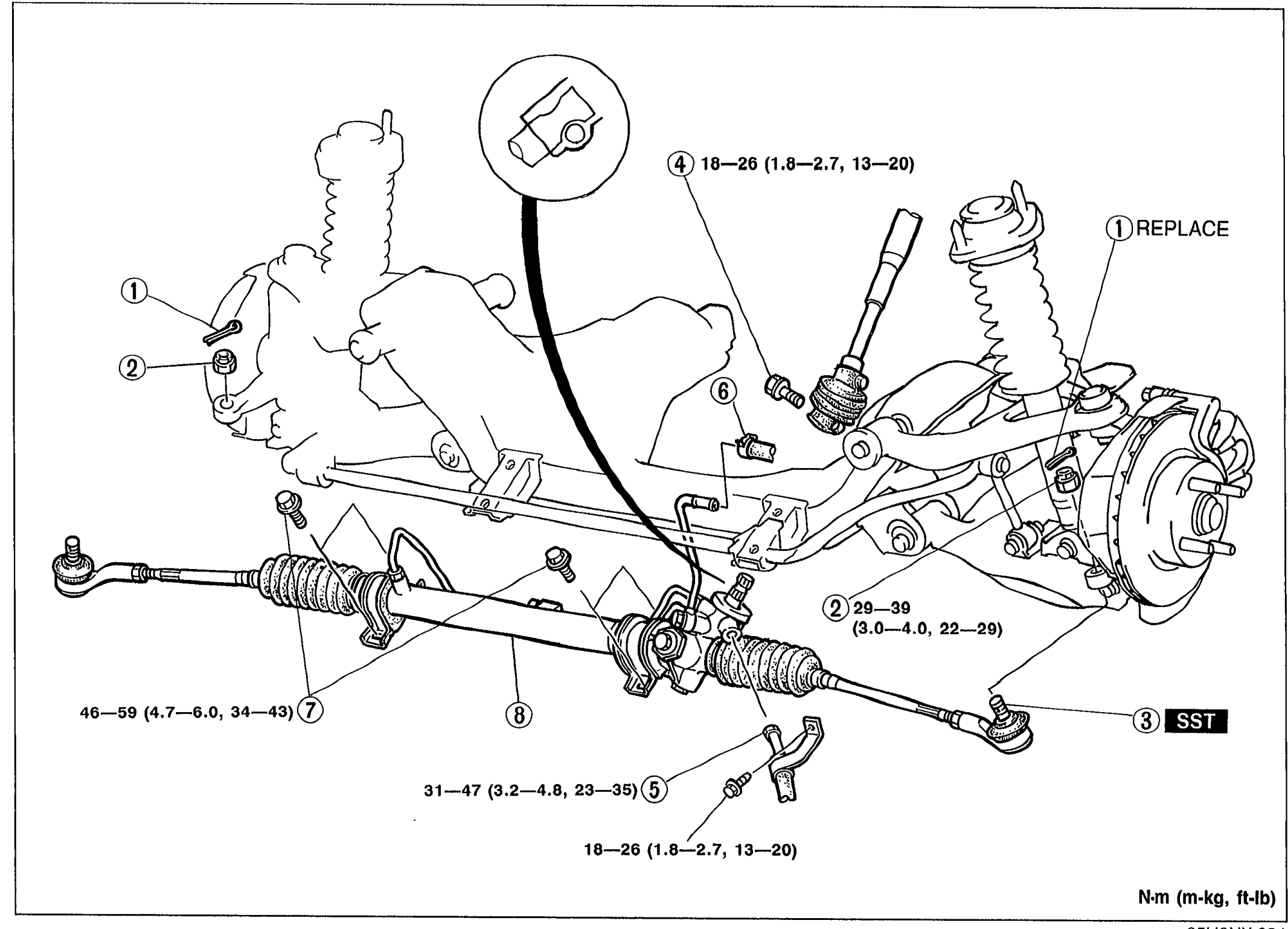
N-19Exploded view of steering gear and linkage assembly with numbered balloons 1-8 and torque values. Shows tie-rod ends, gear housing, pinion shaft, mounting brackets, and pressure pipe. Torque values: 18-26 N·m, 29-39 N·m, 46-59 N·m, 31-47 N·m. Callout 1 marked REPLACE; callout 3 marked SST.
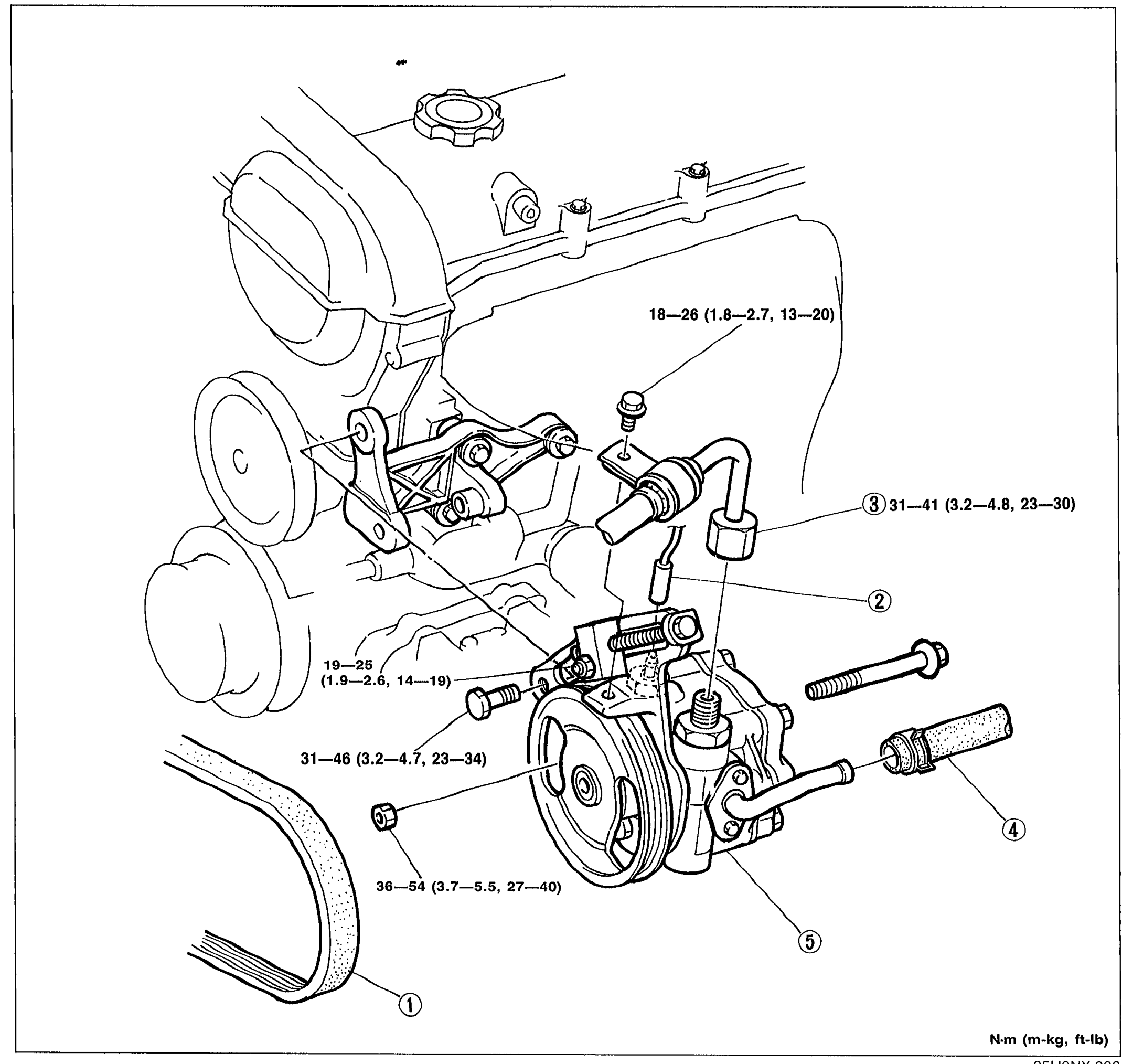
ENGINE SPEED SENSING POWER STEERING — POWER STEERING OIL PUMP
N-21Exploded view of power steering oil pump assembly mounted on engine. Shows drive belt (1), pressure switch connector (2), pressure pipe (3), return hose (4), and oil pump assembly (5). Torque values labeled: 18-26 N·m, 31-41 N·m, 19-25 N·m, 31-46 N·m, 36-54 N·m.
Braking System
P13 diagrams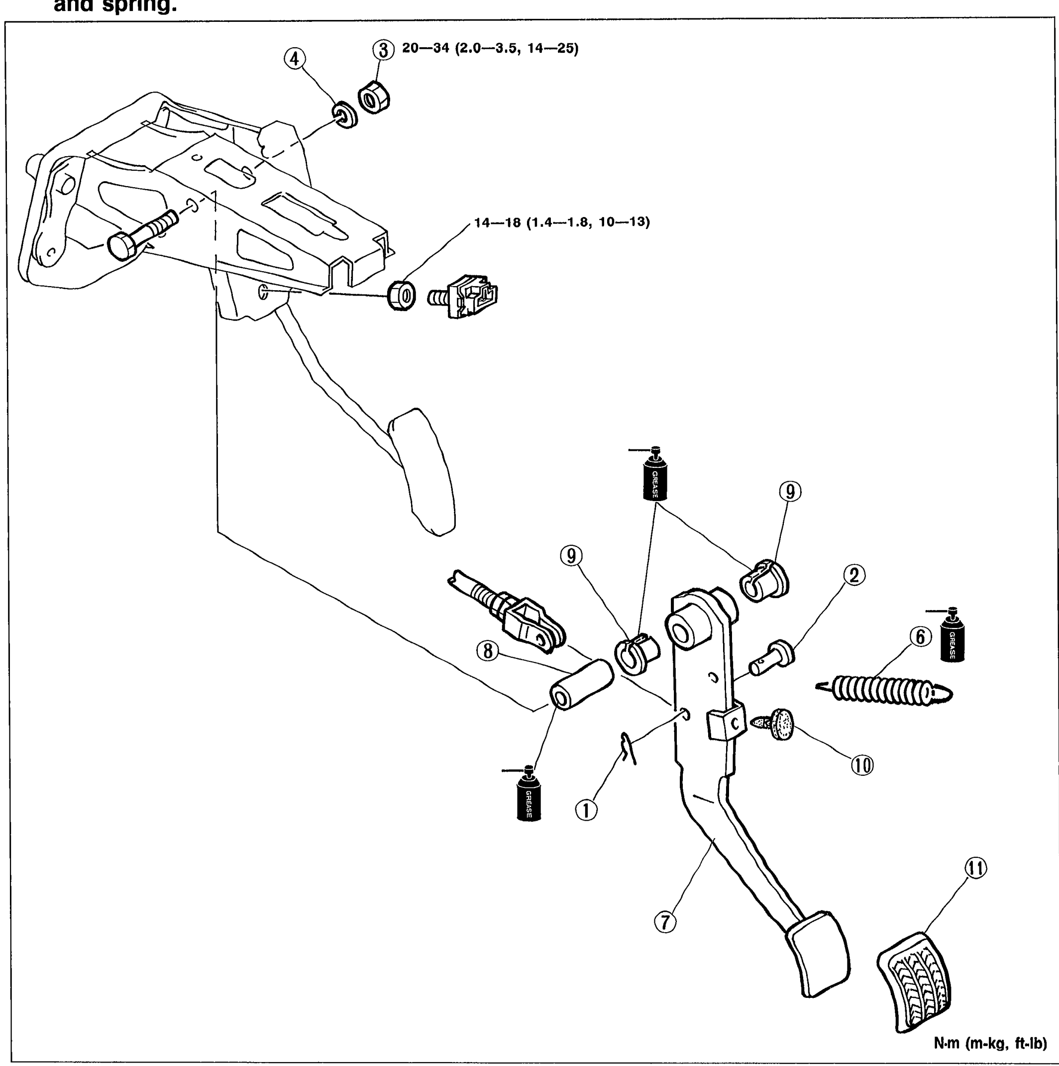
BRAKE SYSTEM
P-9Exploded view of the brake pedal assembly showing the pedal bracket, clevis pin (2), nut (3), spring washer (4), bolt (5), return spring (6), brake pedal (7), guide pipe (8), bushing (9), stopper rubber (10), and pedal pad (11). Spring clip (1) is also shown. Tightening torques displayed: 20—34 N·m (2.0—3.5 m-kg, 14—25 ft-lb) at the upper bracket bolts, 14—18 N·m (1.4—1.8 m-kg, 10—13 ft-lb) at another fastener.
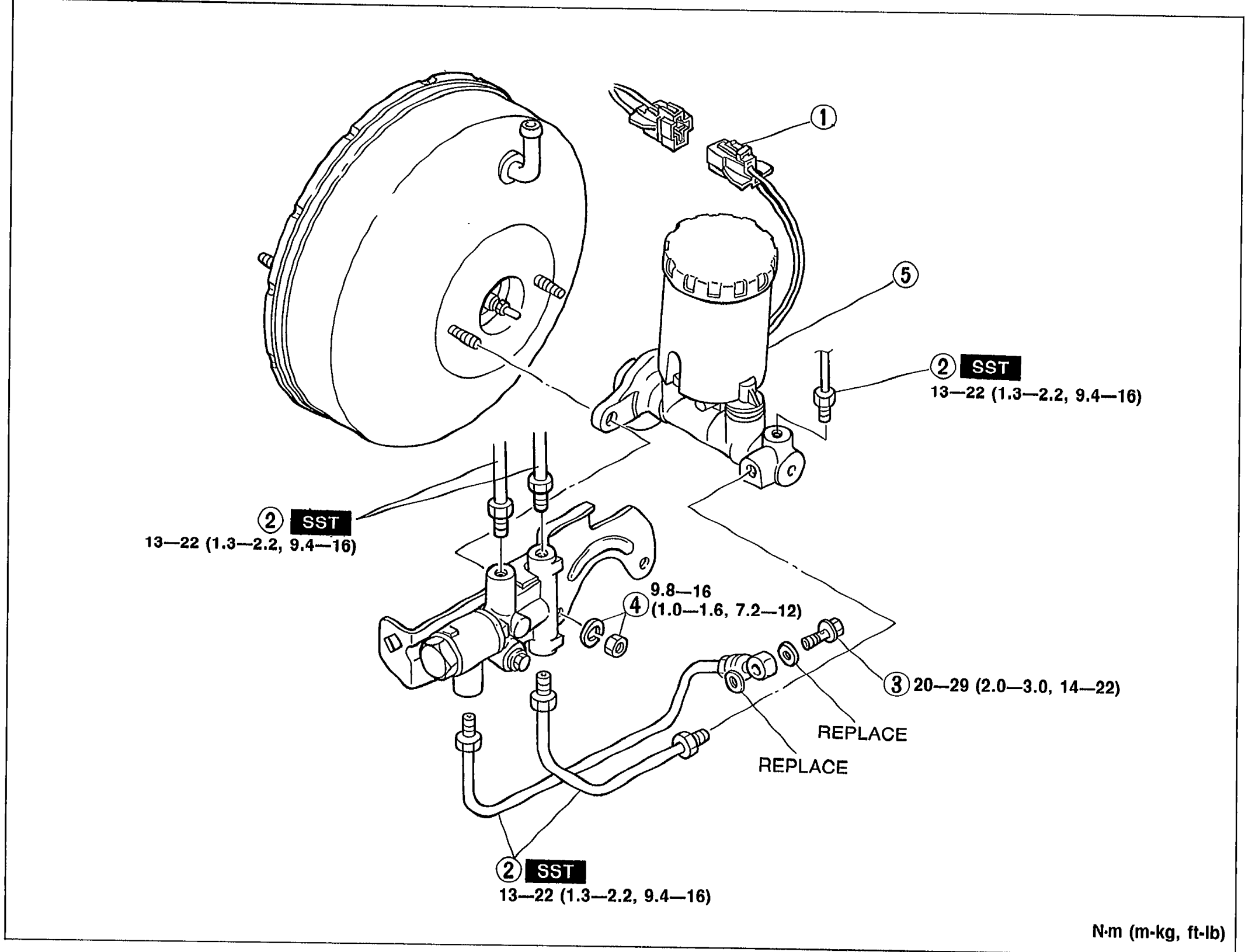
BRAKE SYSTEM
P-10Exploded view of the master cylinder assembly mounted on the power brake unit. Callouts: 1 (fluid level sensor connector at reservoir top), 2 (brake pipe connections, marked SST — torque 13—22 N·m, 1.3—2.2 m-kg, 9.4—16 ft-lb), 3 (REPLACE — washers, 20—29 N·m, 2.0—3.0 m-kg, 14—22 ft-lb), 4 (nut and washer, 9.8—16 N·m, 1.0—1.6 m-kg, 7.2—12 ft-lb), 5 (reservoir and master cylinder).
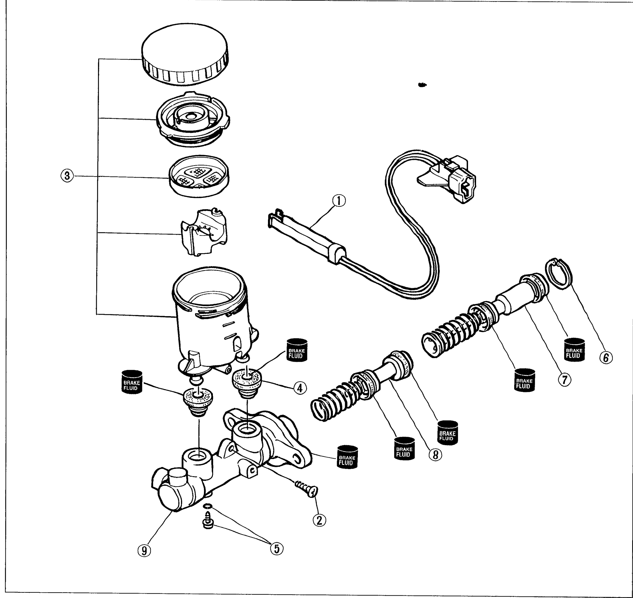
BRAKE SYSTEM
P-12Exploded view of the master cylinder assembly showing the fluid level sensor (1), screw (2), reservoir assembly (3) with cap, diaphragm, and float, bushings (4), stopper screw and O-ring (5), snap ring (6), primary piston assembly (7), secondary piston assembly (8), and cylinder body (9). BRAKE FLUID containers indicate points where brake fluid is applied to seals.
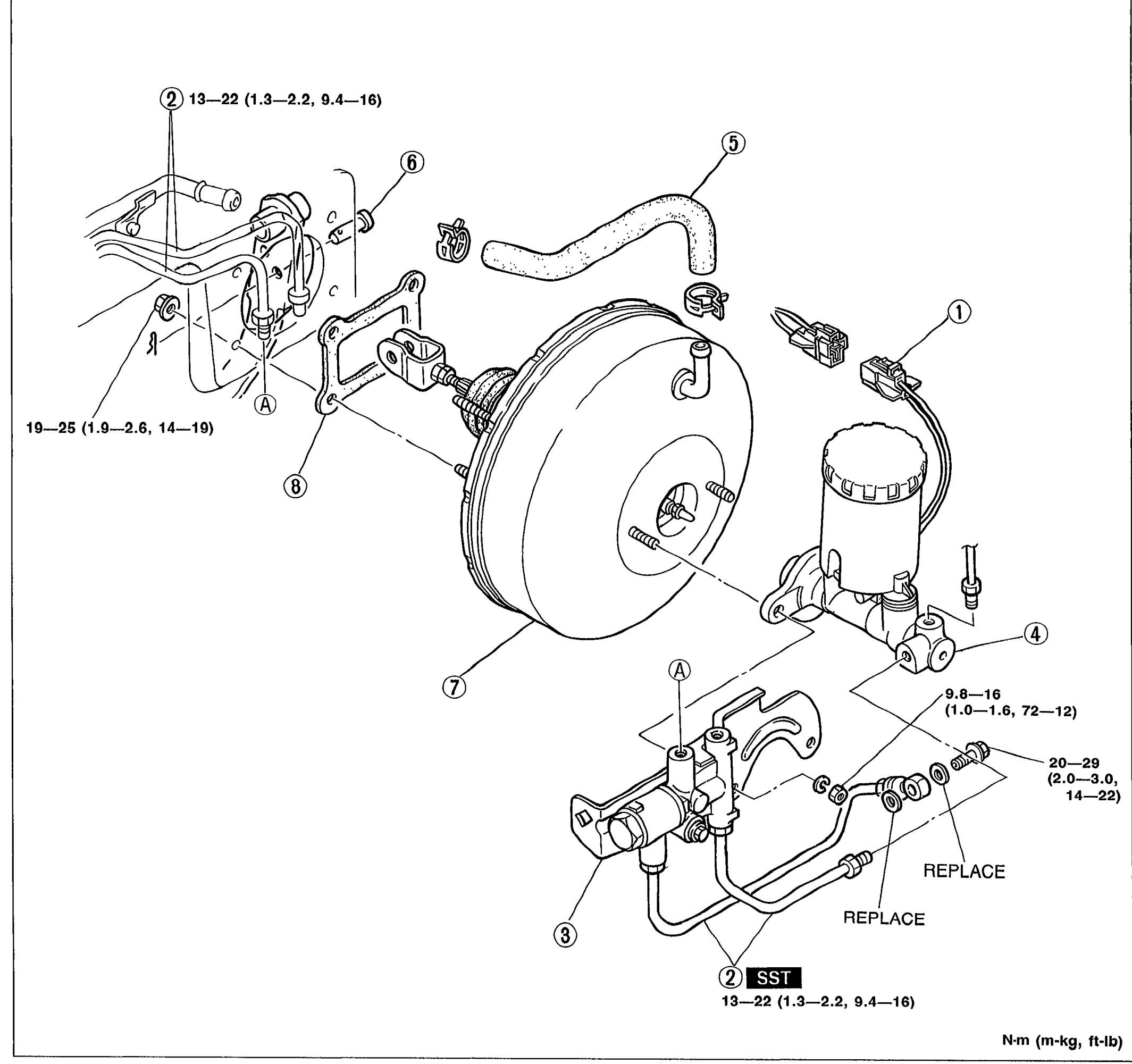
BRAKE SYSTEM
P-15Exploded view of the power brake unit assembly. Shows the master cylinder mounted to the brake booster (power brake unit), with vacuum hose with check valve, proportioning valve, brake pipes, clevis pin, gasket, and fluid level sensor connector. Numbered callouts 1-8 identify components. Letter callouts (A) and (B) appear near torque-stamped fasteners. Tightening torques are shown in N·m (m-kg, ft-lb). An SST marker appears at the bottom near the proportioning valve fitting. REPLACE notes mark two flare-nut fittings.
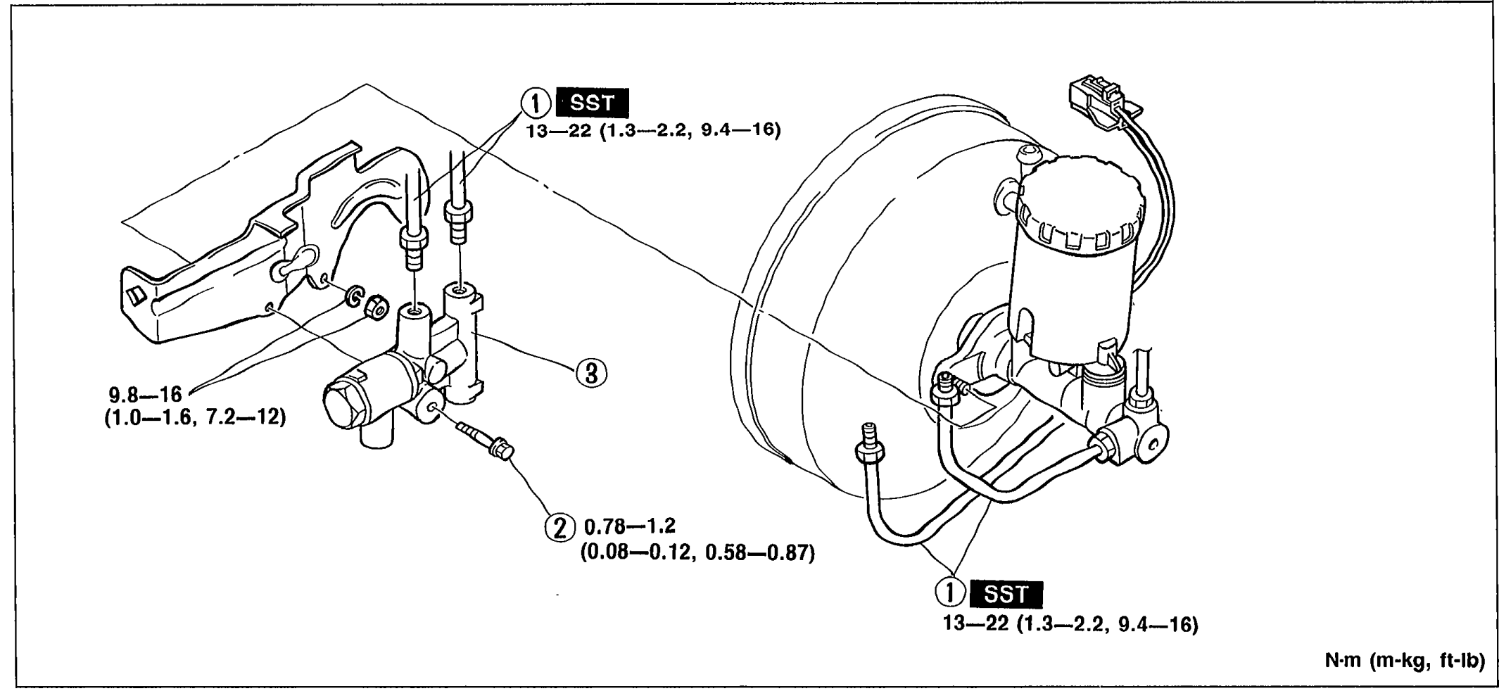
BRAKE SYSTEM — PROPORTIONING BYPASS VALVE
P-16Exploded view of the proportioning bypass valve replacement. Shows the brake pipe (1), bolt (2), and proportioning bypass valve (3) attached at the master cylinder / power brake unit. Tightening torques labeled in N·m (m-kg, ft-lb). SST markers appear at the brake-pipe flare-nut fittings.
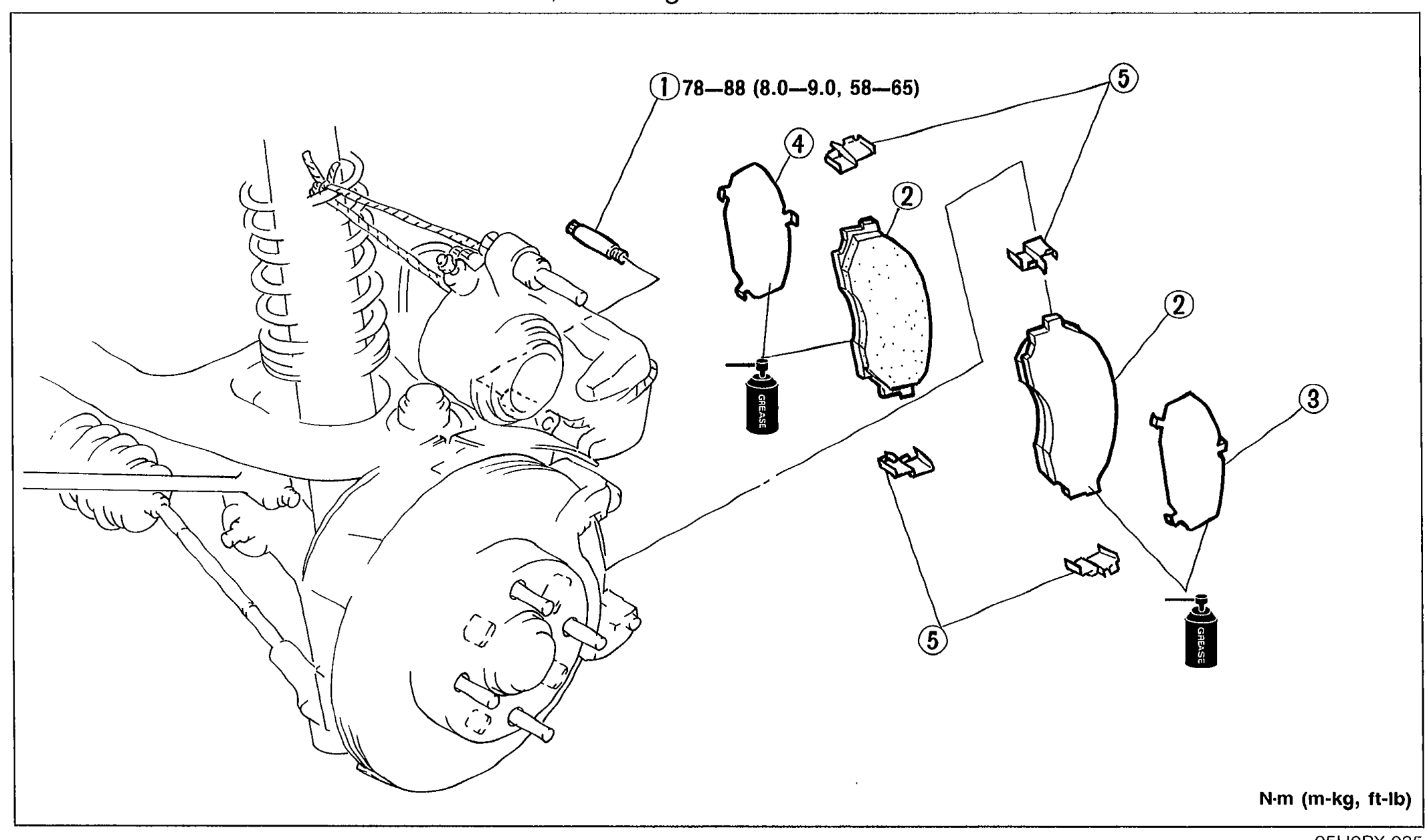
BRAKE SYSTEM — FRONT BRAKE (DISC)
P-18Exploded view of front disc brake pad replacement. Shows the strut/knuckle/rotor assembly on the left and the caliper hardware on the right: lock bolt (1) with 78—88 N·m torque, disc pad (2), outer shim (3), inner shim (4), and guide plate (5). Two grease/lubricant bottle icons appear next to shims indicating apply grease.
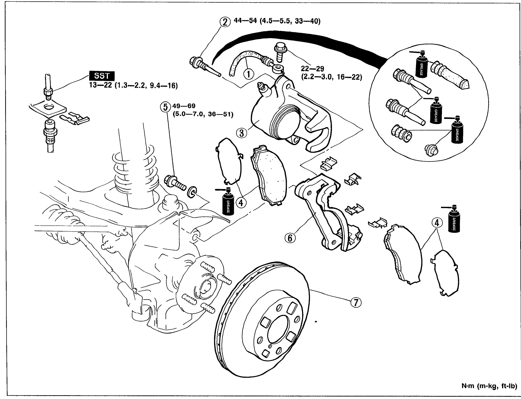
BRAKE SYSTEM — Installation / Removal / Installation (Caliper)
P-19Exploded view of front brake caliper removal/installation. Shows the strut and rotor on the left, then the caliper assembly with brake hose (1), lock bolts (2) with 44—54 N·m torque, brake caliper assembly (3) with 49—69 N·m torque, disc pad assembly (4), bolt (5) with 22—29 N·m torque, mounting support (6), and disc plate (7). SST marker is present at the brake-hose flare-nut fitting (13—22 N·m). Grease bottle icons appear next to slide pins and shims indicating apply grease.
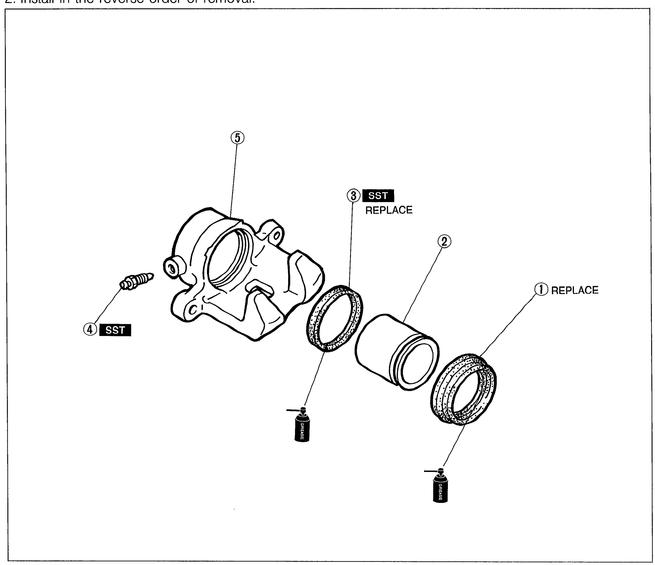
BRAKE SYSTEM — CALIPER Disassembly / Inspection / Assembly
P-21Exploded view of the front brake caliper showing the caliper body (5) on the left with bleeder screw (4) attached, then piston seal (3) marked SST and REPLACE, piston (2), and dust seal (1) marked REPLACE. Two grease bottle icons indicate apply grease to the piston seal and piston.
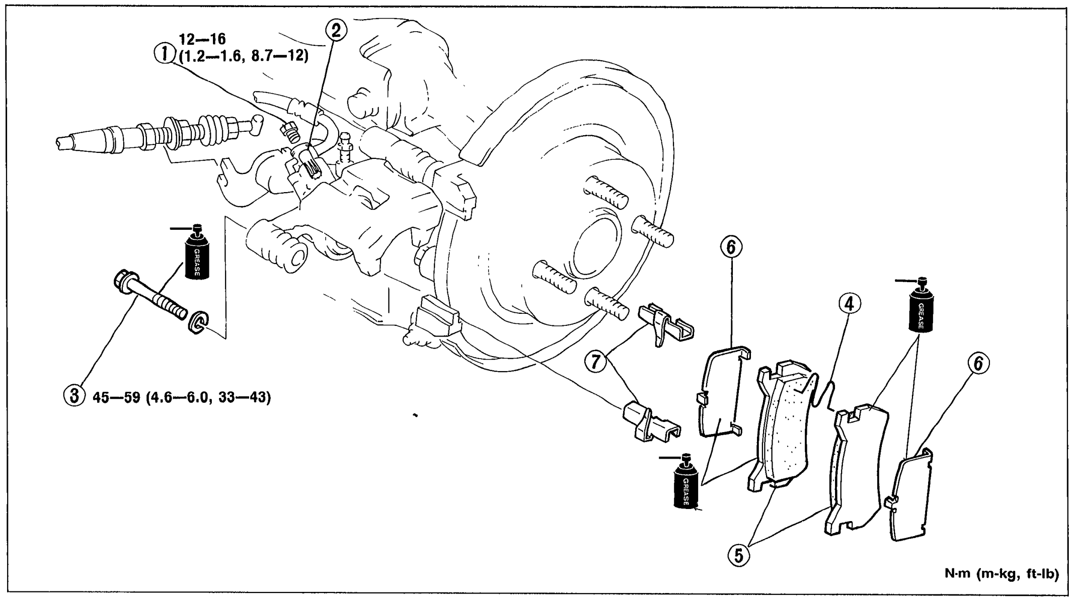
BRAKE SYSTEM — REAR BRAKE (DISC)
P-22Exploded view of the rear disc-brake pad replacement. Shows the caliper/rotor assembly with plug (1) with 12—16 N·m torque, manual adjustment gear (2), lock bolt (3) with 45—59 N·m torque, M-spring (4), disc pad (5), shim (6), and guide plate (7). Grease bottle icons indicate apply grease.
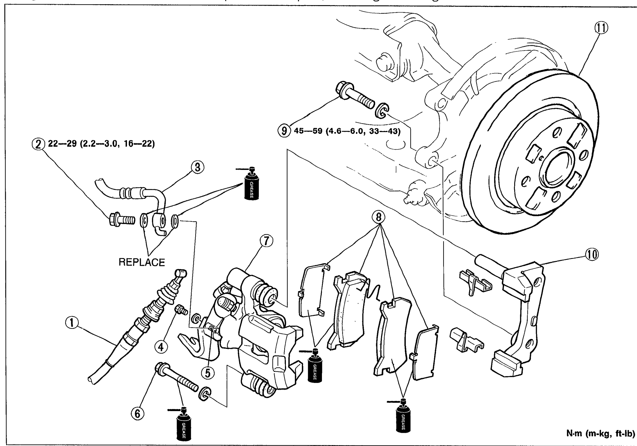
BRAKE SYSTEM — Installation note / Removal / Installation (Rear Caliper)
P-23Exploded view of rear brake caliper removal/installation. Shows parking cable (1), connecting bolt (2) with 22—29 N·m torque, brake hose (3) marked REPLACE, plug (4), manual adjustment gear (5), lock bolt (6) with 45—59 N·m torque, caliper (7), disc pad assembly (8), bolt (9), mounting support (10), and disc plate (11). Grease bottle icons indicate apply grease.
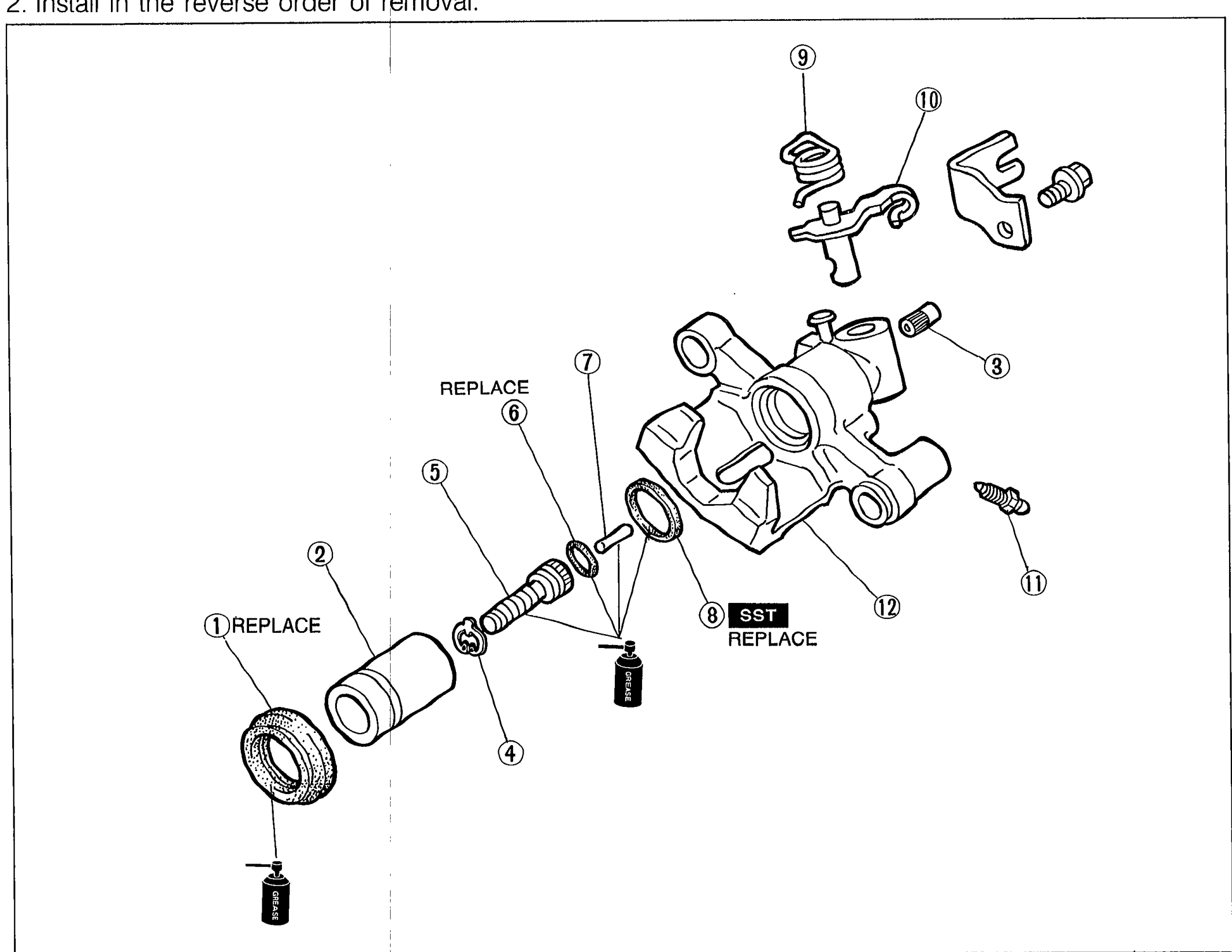
BRAKE SYSTEM - CALIPER
P-25Exploded view of rear brake caliper assembly showing 12 numbered components with REPLACE labels on parts 1 and 6, and SST REPLACE label on part 8. Components include dust seal, piston, manual adjustment gear, snap ring, adjusting bolt, O-ring, connecting link, piston seal, spring, operating lever, cap and bleeder screw, and caliper body.
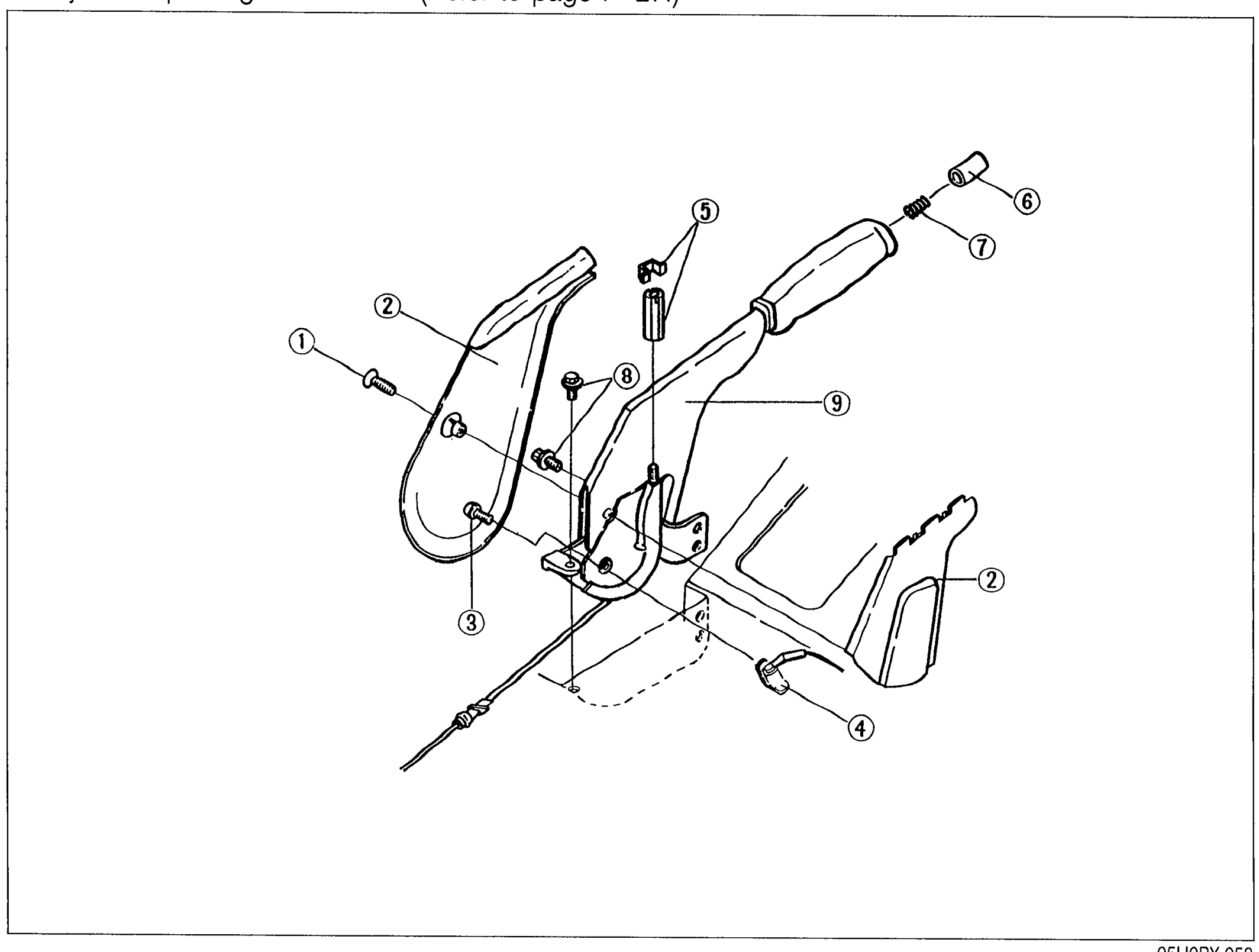
PARKING BRAKE SYSTEM - Removal / Inspection / Installation
P-28Exploded view of the parking brake lever assembly showing 9 numbered components: screw, cover, bolt, parking brake switch, adjusting nut and clip, cap, spring, bolt, and parking brake lever.
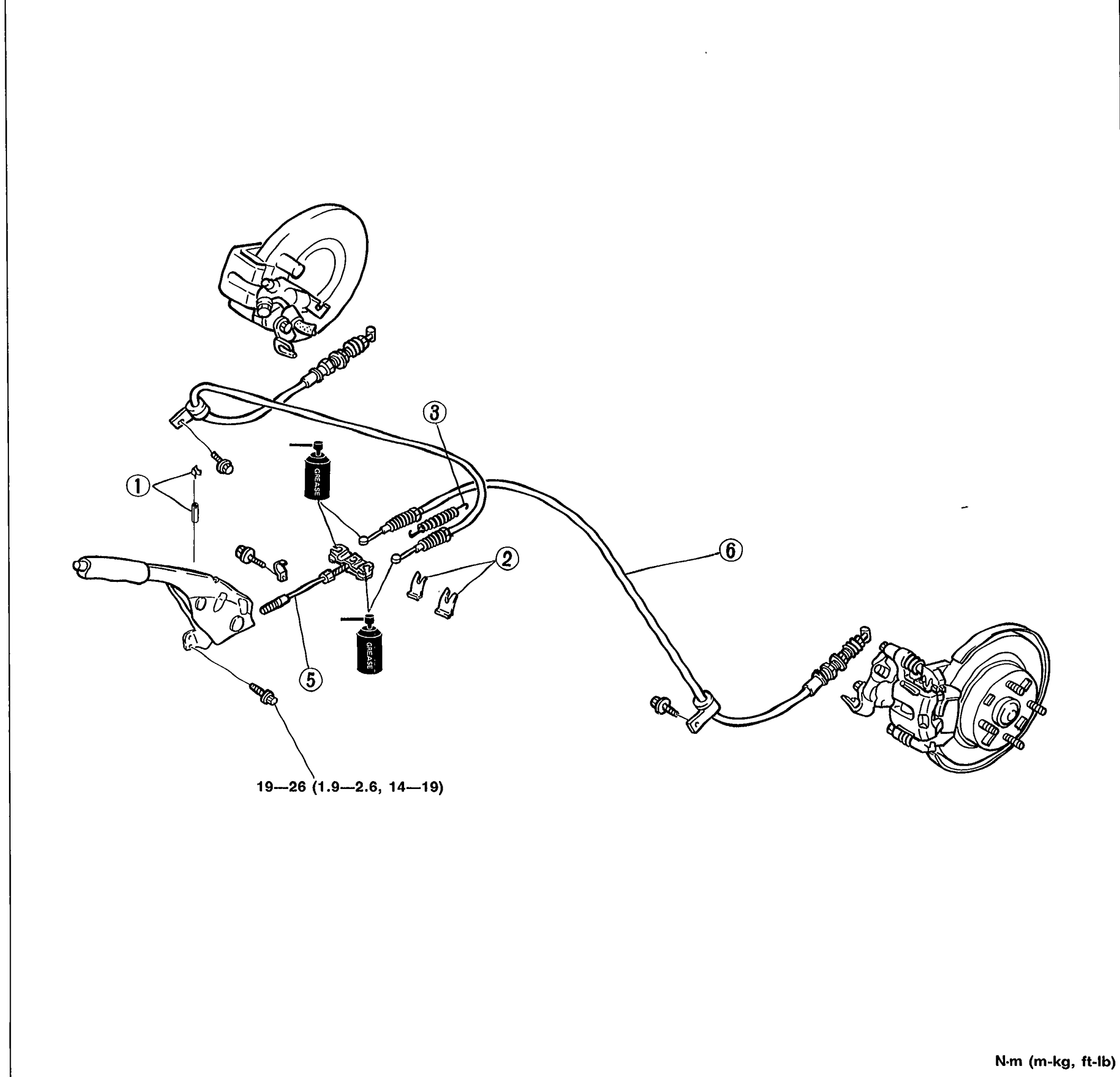
PARKING BRAKE SYSTEM - PARKING BRAKE CABLE
P-29Exploded view of the parking brake cable assembly showing the lever, cables routing from the parking brake lever to both rear brake assemblies, and 6 numbered components: adjusting nut and clip, clip, spring, front cable, rear cable. Torque spec marked 19—26 N·m (1.9—2.6 m-kg, 14—19 ft-lb).
Suspension
R13 diagrams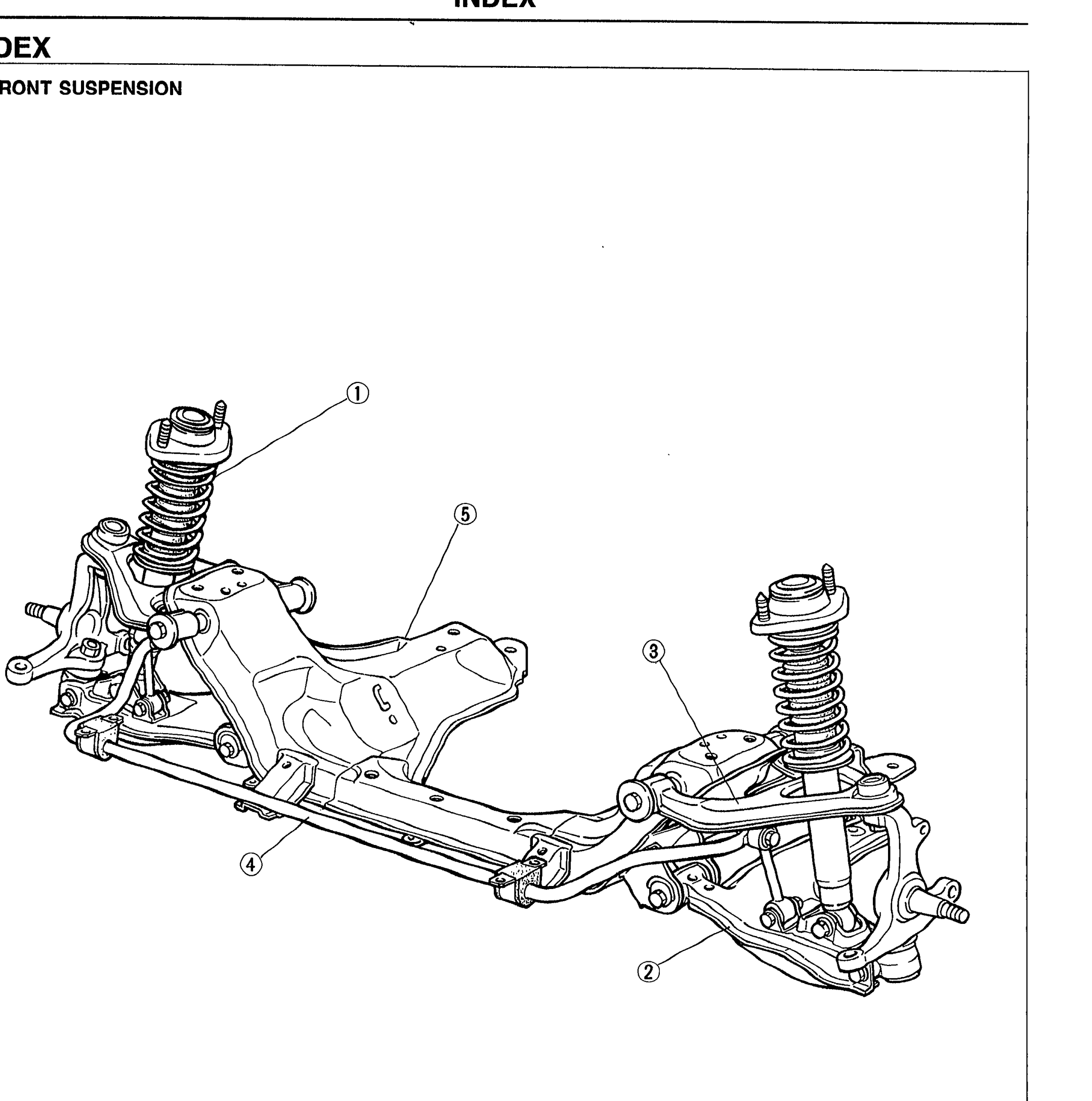
INDEX
R-2Exploded illustration of the MX-5 front suspension assembly (double-wishbone) viewed from the front. Numbered callouts identify five major sub-assemblies: 1 Shock absorber and spring, 2 Lower arm, 3 Upper arm, 4 Stabilizer, 5 Crossmember.
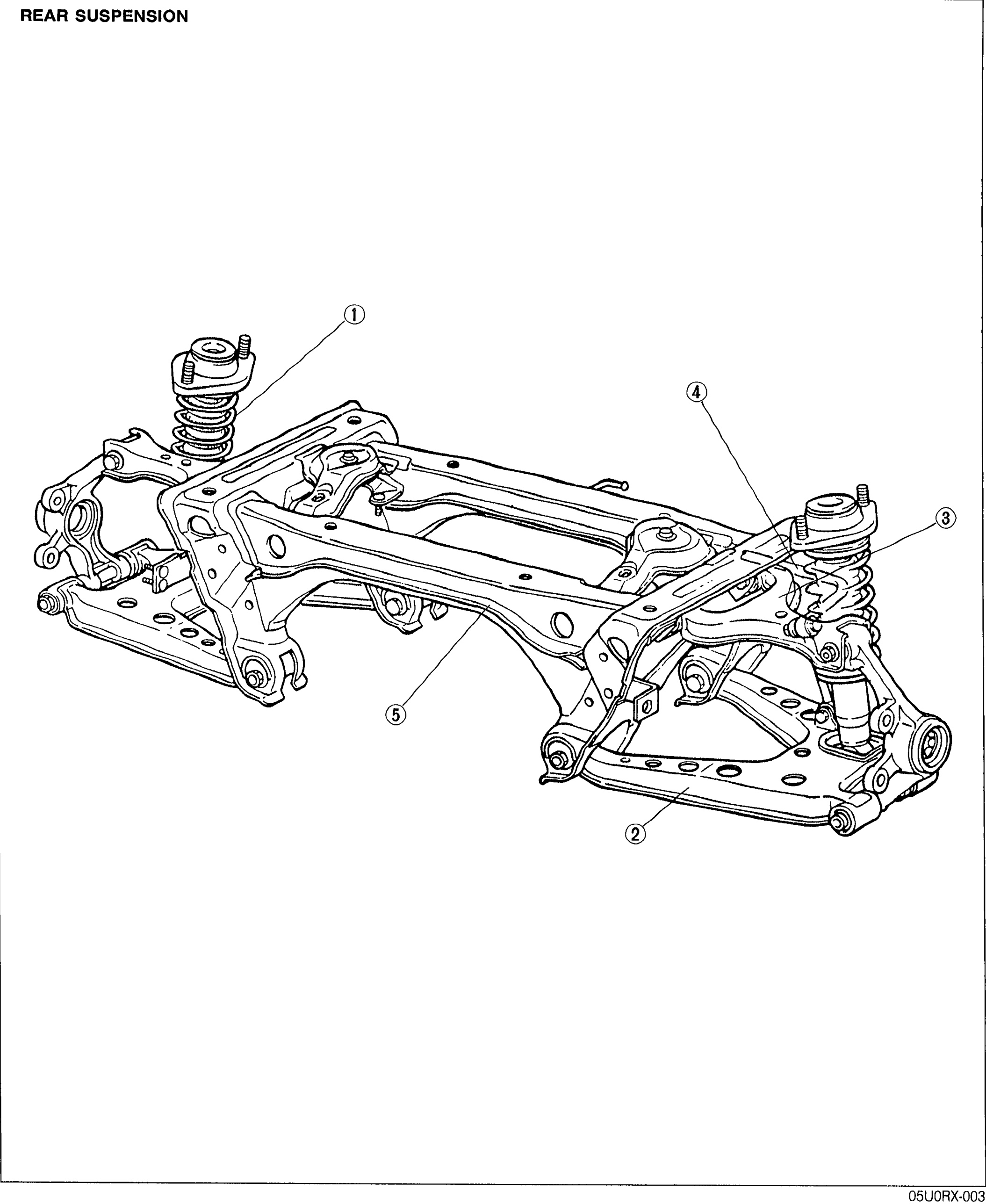
INDEX
R-3Exploded illustration of the MX-5 rear suspension assembly (double-wishbone) viewed from the rear. Numbered callouts identify five major sub-assemblies: 1 Shock absorber and spring, 2 Lower arm, 3 Upper arm, 4 Stabilizer, 5 Crossmember.
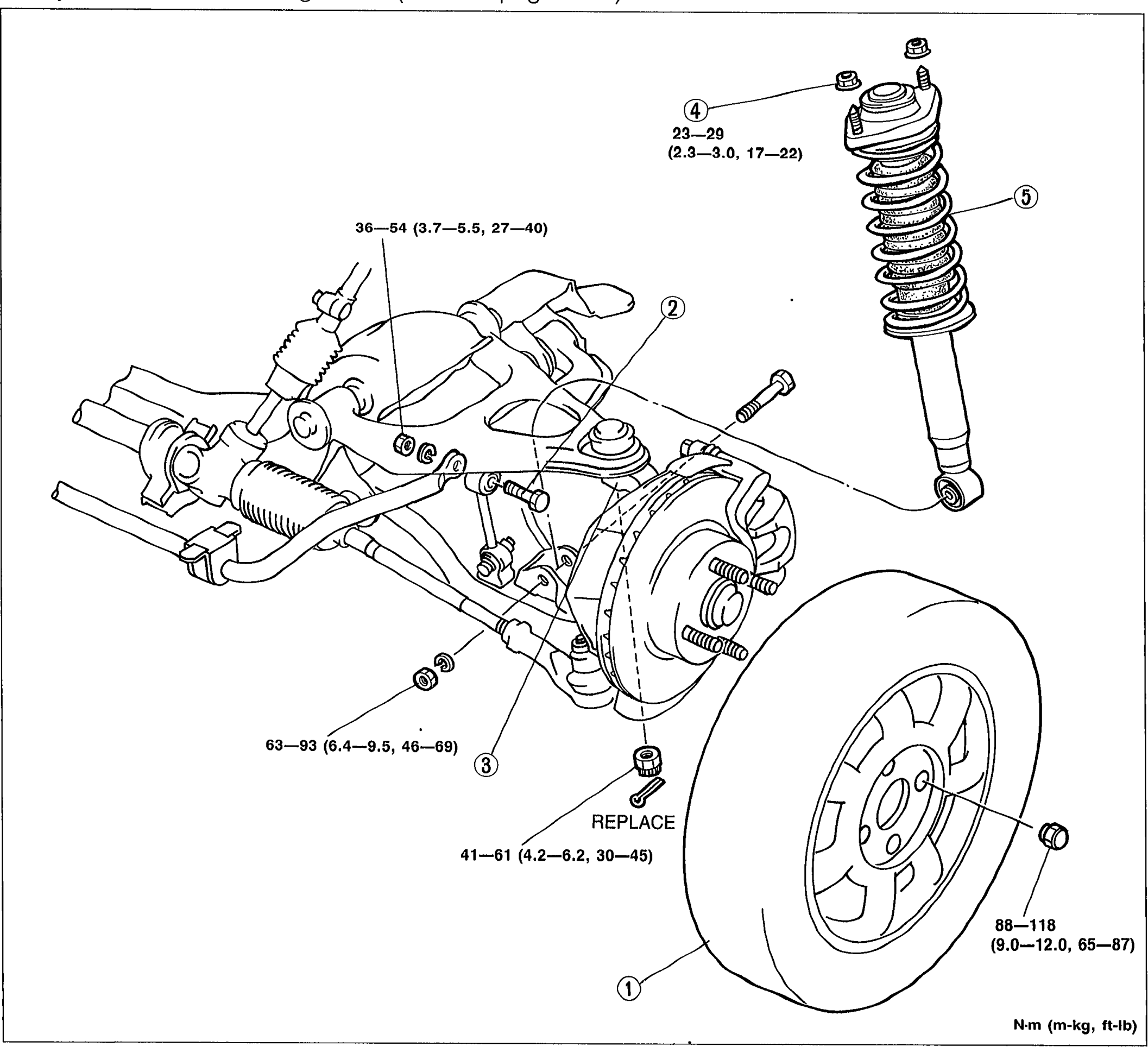
FRONT SUSPENSION (DOUBLE-WISHBONE) - SHOCK ABSORBER AND SPRING
R-12Exploded view of the front shock absorber and spring assembly with wheel/tire on the right and the upper/lower arm assembly on the left. Numbered callouts (1) wheel and tire, (2) stabilizer control link bolt, (3) upper arm ball joint (REPLACE), (4) mounting plate nut, (5) shock absorber and spring. Torque values are annotated next to each fastener in N-m (m-kg, ft-lb).
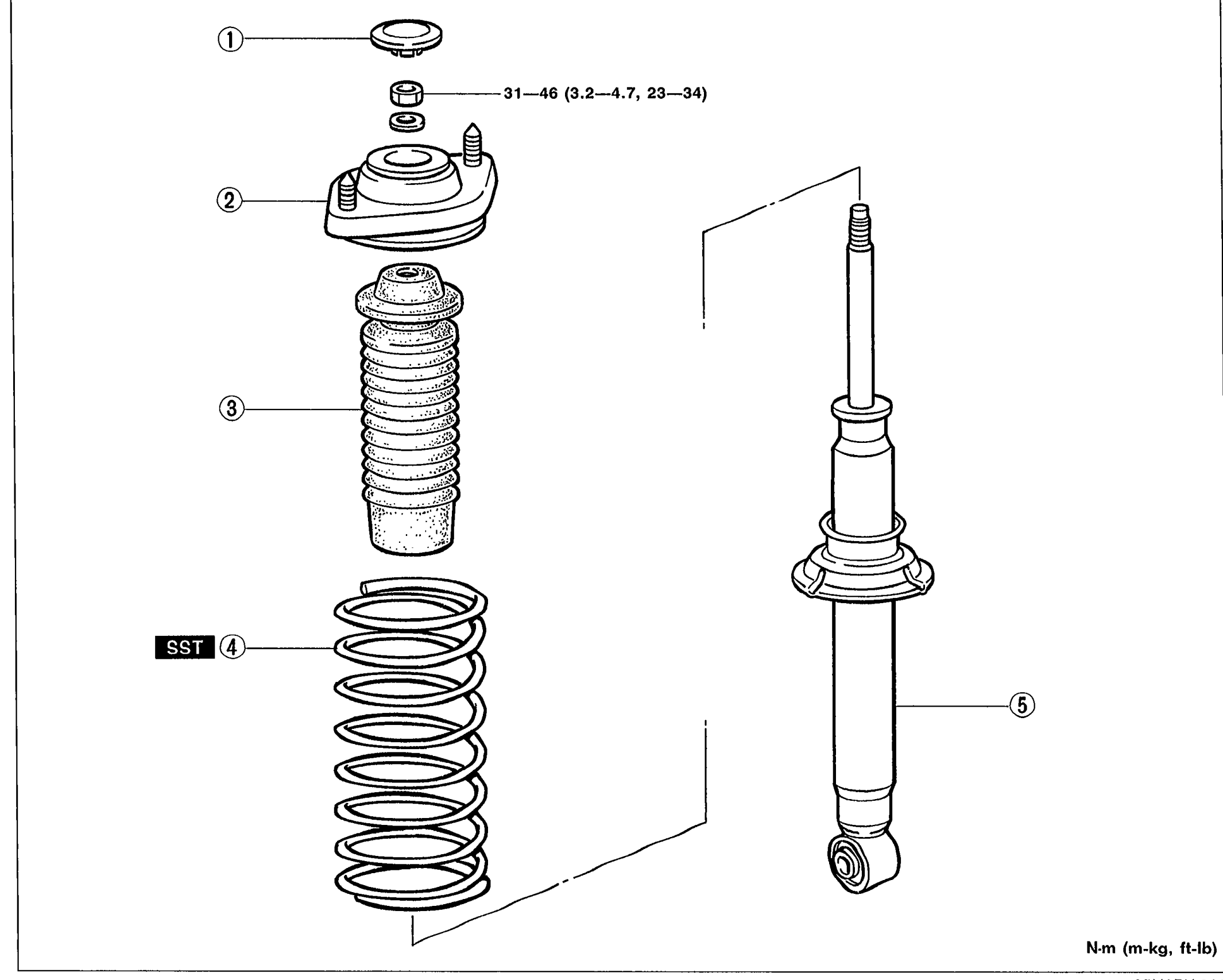
FRONT SUSPENSION (DOUBLE-WISHBONE) - Shock Absorber and Spring
R-13Exploded view of the shock absorber and spring disassembly. Numbered callouts (1) cap, (2) mounting plate, (3) bound stopper, (4) coil spring (with SST tag), (5) shock absorber. Torque value 31-46 N-m (3.2-4.7, 23-34) shown for the mounting plate nut.
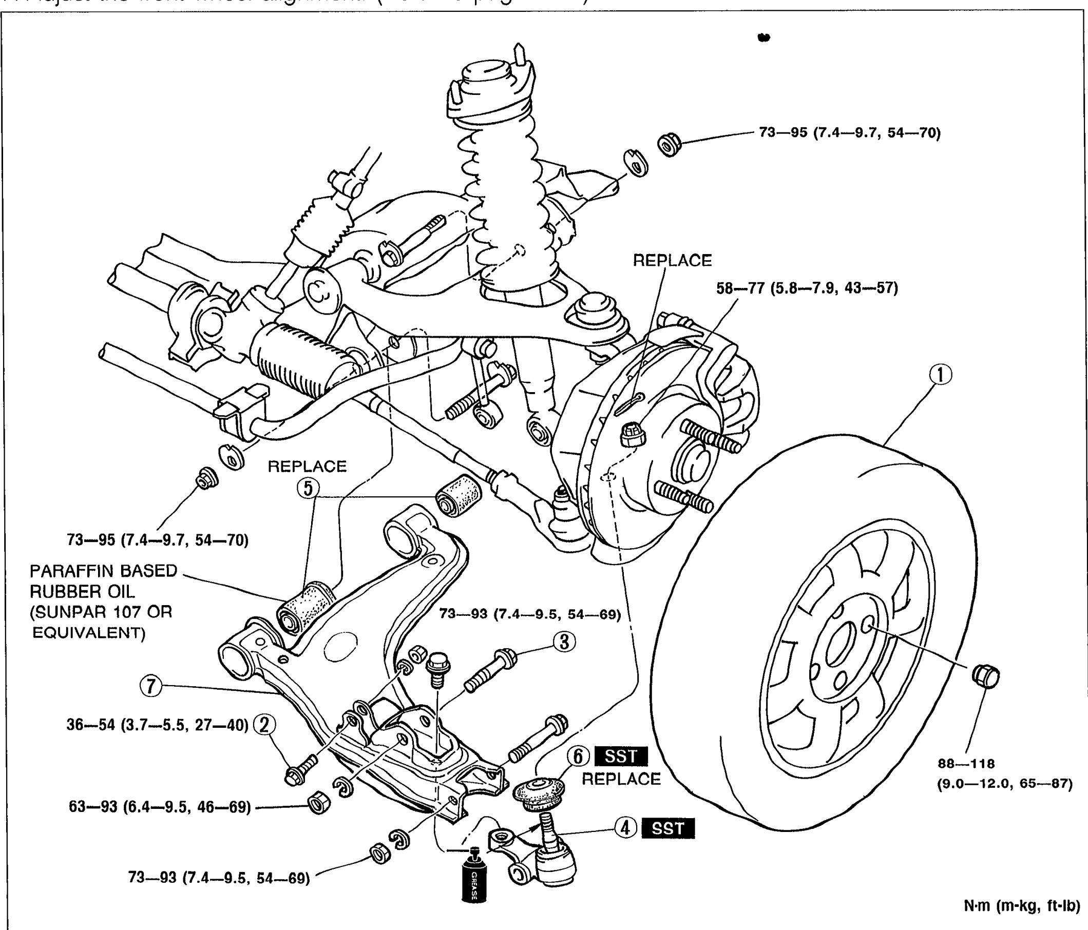
FRONT SUSPENSION (DOUBLE-WISHBONE) - LOWER ARM
R-15Exploded view of front double-wishbone lower arm assembly. Numbered callouts: (1) wheel and tire, (2) stabilizer control link bolt, (3) shock absorber bolt, (4) lower arm ball joint, (5) lower arm bushing (front and rear), (6) ball joint dust boot, (7) lower arm. Torque values annotated next to fasteners in N-m (m-kg, ft-lb). 'REPLACE' tags shown on ball joint and bushings. PARAFFIN BASED RUBBER OIL (SUNPAR 107 OR EQUIVALENT) note next to bushing.
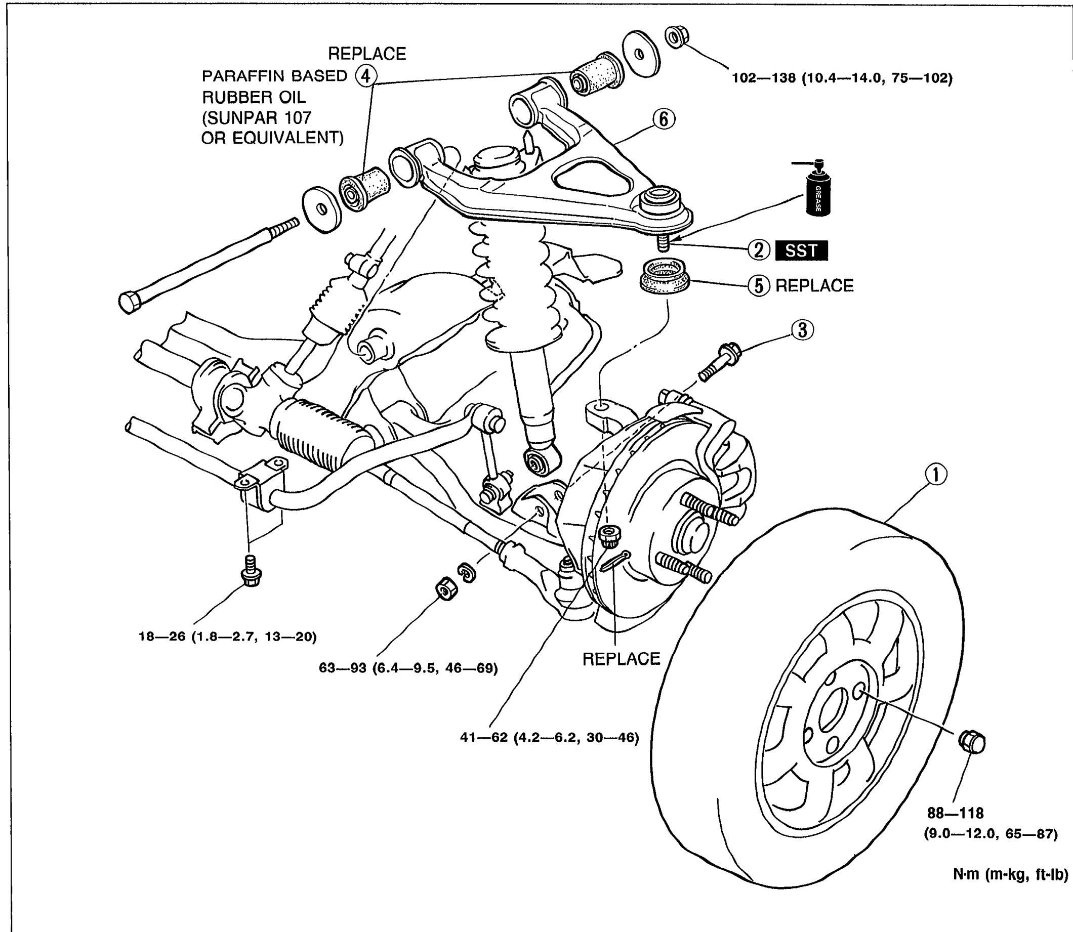
FRONT SUSPENSION (DOUBLE-WISHBONE) - UPPER ARM
R-17Exploded view of front upper arm assembly. Numbered callouts (1) wheel and tire, (2) upper arm ball joint (REPLACE / SST), (3) shock absorber bolt, (4) upper arm bushing (front and rear) - PARAFFIN BASED RUBBER OIL (SUNPAR 107 OR EQUIVALENT), (5) ball joint dust boot (REPLACE), (6) upper arm (REPLACE). Torque values annotated in N-m (m-kg, ft-lb).
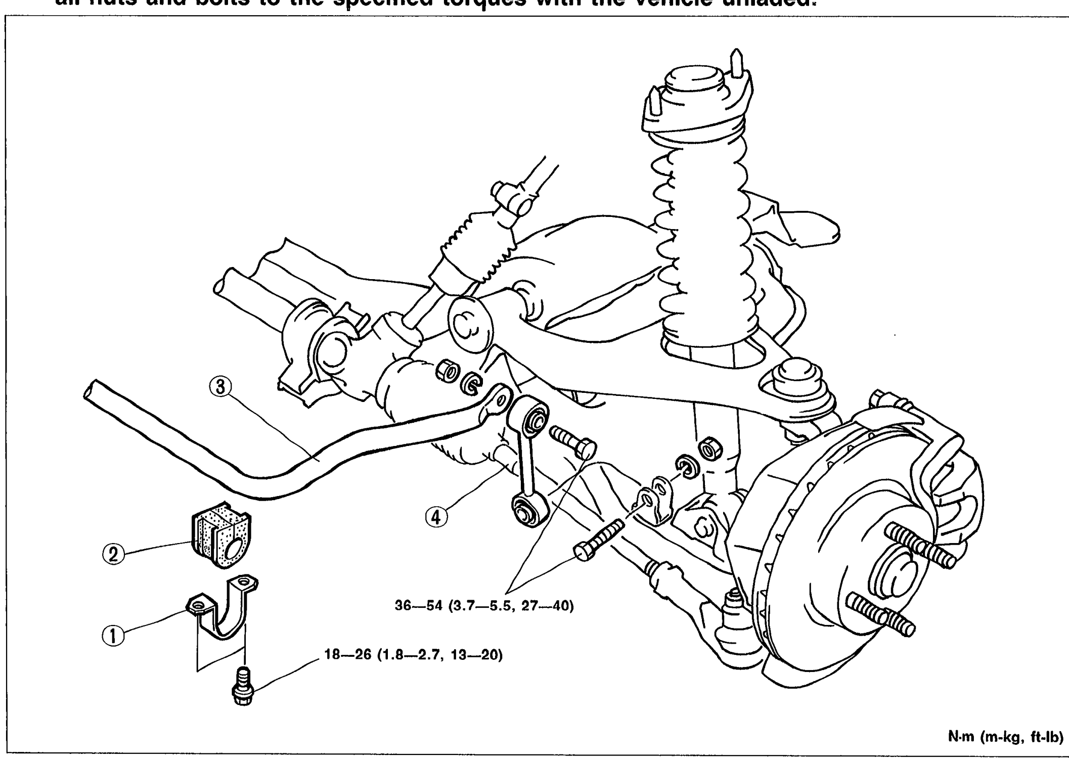
FRONT SUSPENSION (DOUBLE-WISHBONE) - STABILIZER
R-19Exploded view of front stabilizer assembly. Numbered callouts (1) stabilizer bracket, (2) stabilizer bushing, (3) stabilizer, (4) stabilizer control link. Torque values: 18-26 N-m (1.8-2.7, 13-20) for the bracket and 36-54 N-m (3.7-5.5, 27-40) for control link.
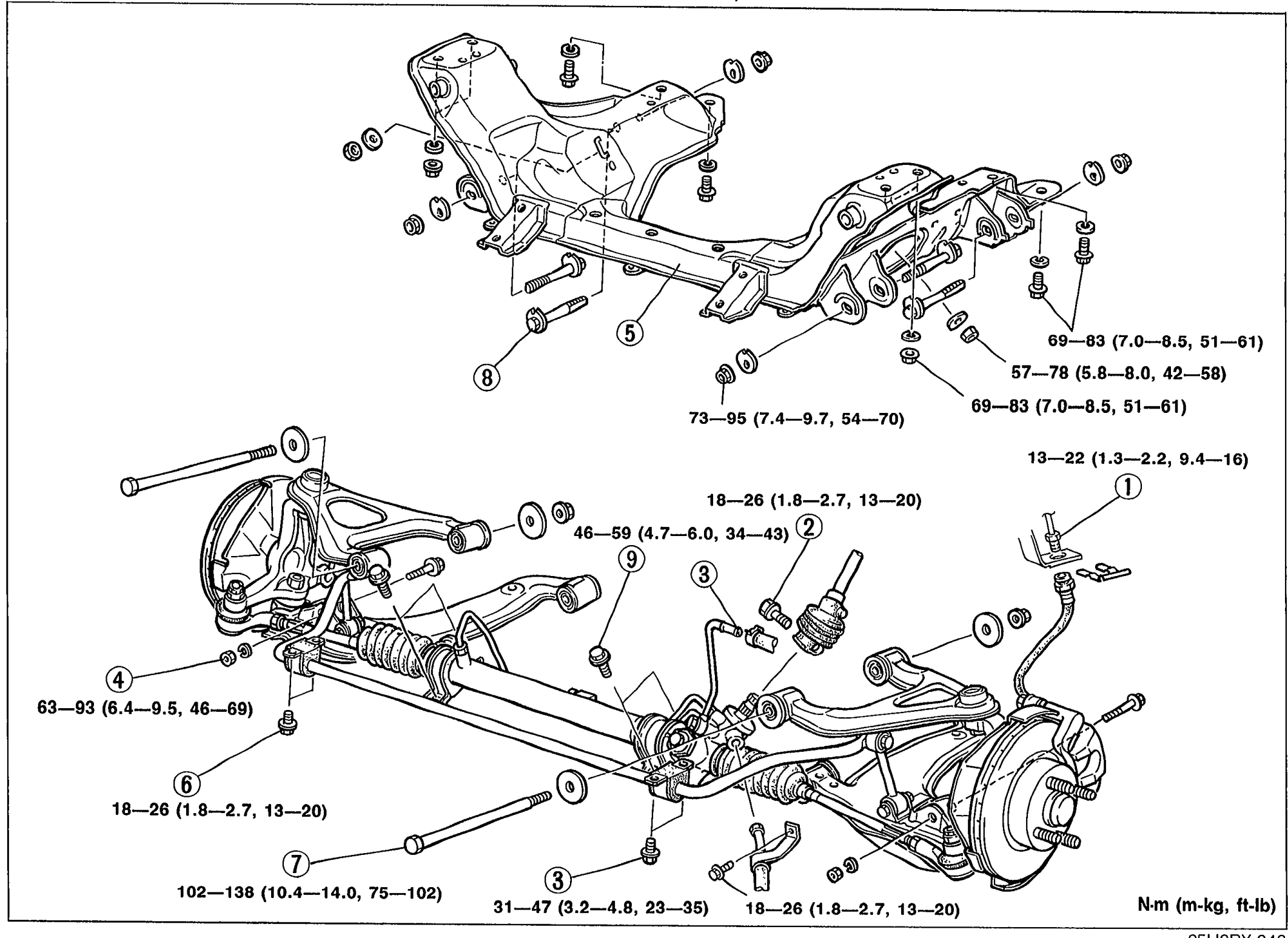
FRONT SUSPENSION (DOUBLE-WISHBONE) - CROSSMEMBER
R-20Exploded view of the front crossmember assembly with all associated components. Numbered callouts (1) brake pipe, (2) pinion shaft bolt, (3) power steering pipe, (4) shock absorber bolt, (5) front crossmember assembly, (6) stabilizer bracket, (7) upper arm bolt, (8) lower arm bolt, (9) steering gear bracket bolt. Multiple torque values shown in N-m (m-kg, ft-lb).
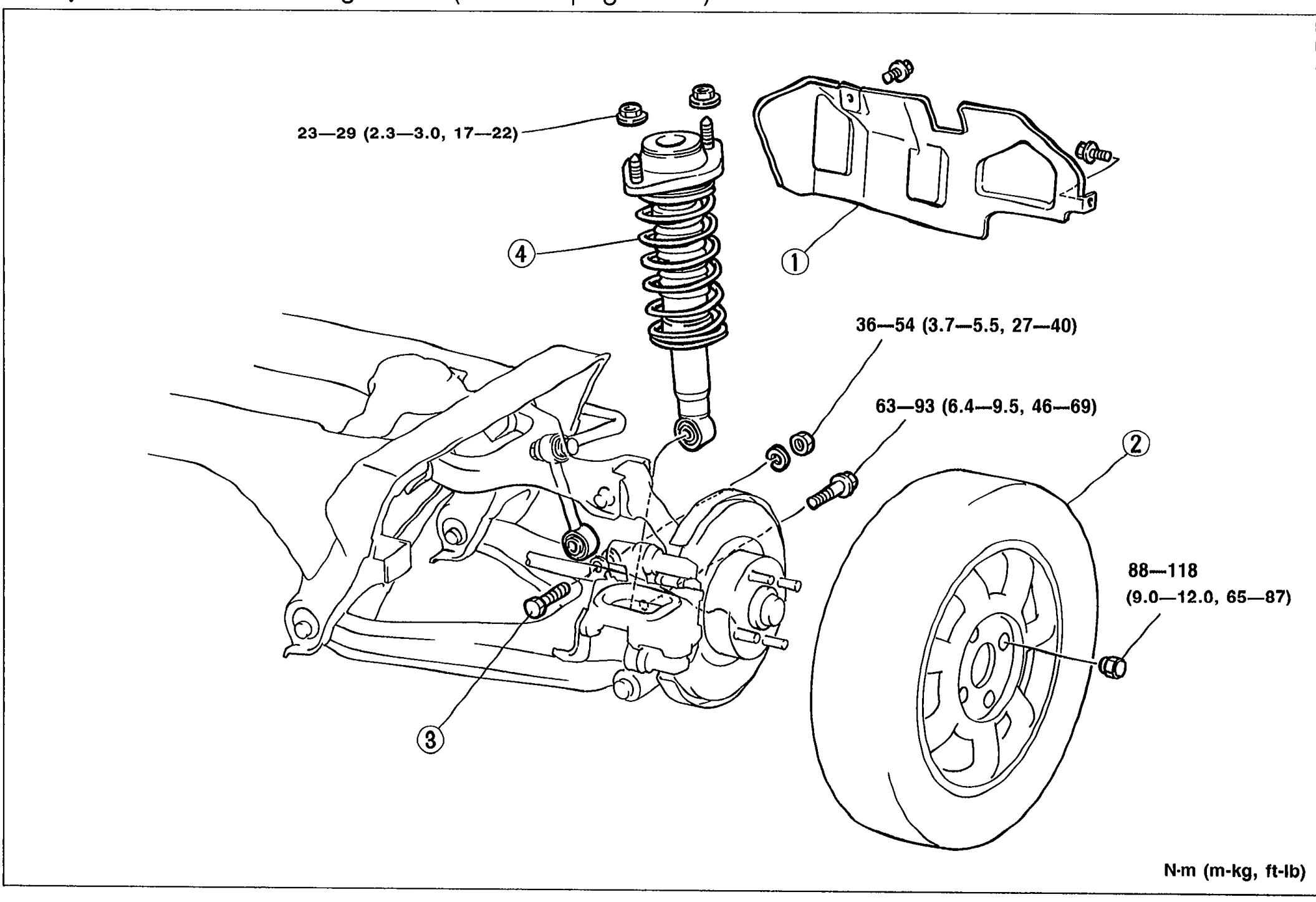
SHOCK ABSORBER AND SPRING - Removal / Installation
R-22Exploded view of rear suspension shock absorber and spring assembly. Shows numbered callouts: (1) Filler pipe protector (left side), (2) Wheel and tire, (3) Stabilizer control link bolt, (4) Shock absorber and spring. Torque specs in N-m (m-kg, ft-lb) shown at fastener locations: 23-29 (2.3-3.0, 17-22), 36-54 (3.7-5.5, 27-40), 63-93 (6.4-9.5, 46-69), 88-118 (9.0-12.0, 65-87).
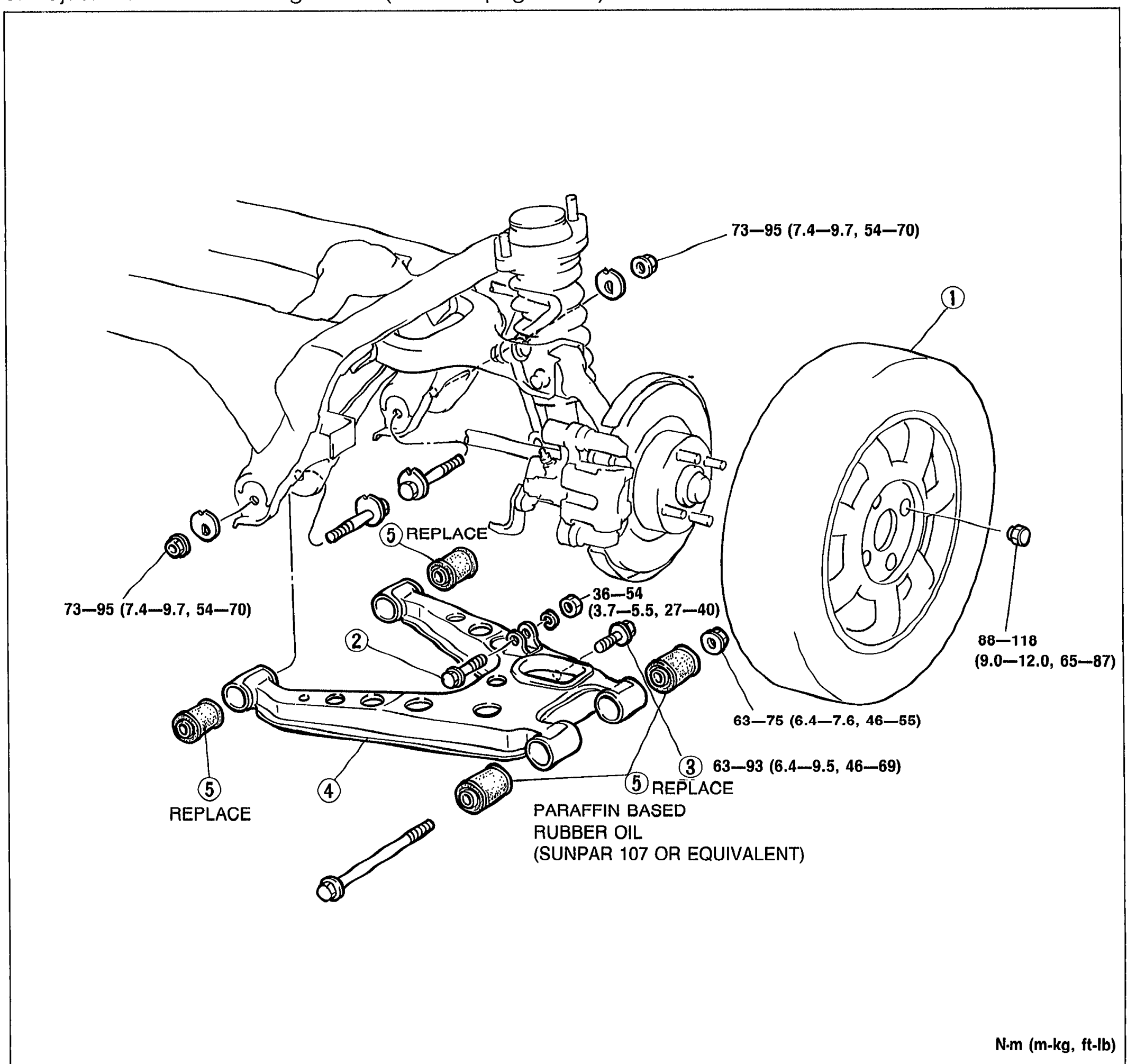
LOWER ARM - Removal / Inspection / Installation
R-23Exploded view of the rear lower arm assembly. Numbered callouts: (1) Wheel and tire, (2) Stabilizer control link bolt, (3) Shock absorber bolt, (4) Lower arm, (5) Lower arm bushing (with REPLACE labels at multiple bushing locations). Notes: PARAFFIN BASED RUBBER OIL (SUNPAR 107 OR EQUIVALENT). Torque specs in N-m (m-kg, ft-lb): 73-95 (7.4-9.7, 54-70) at upper inner pivot, 36-54 (3.7-5.5, 27-40), 63-75 (6.4-7.6, 46-55), 63-93 (6.4-9.5, 46-69), 88-118 (9.0-12.0, 65-87) wheel.
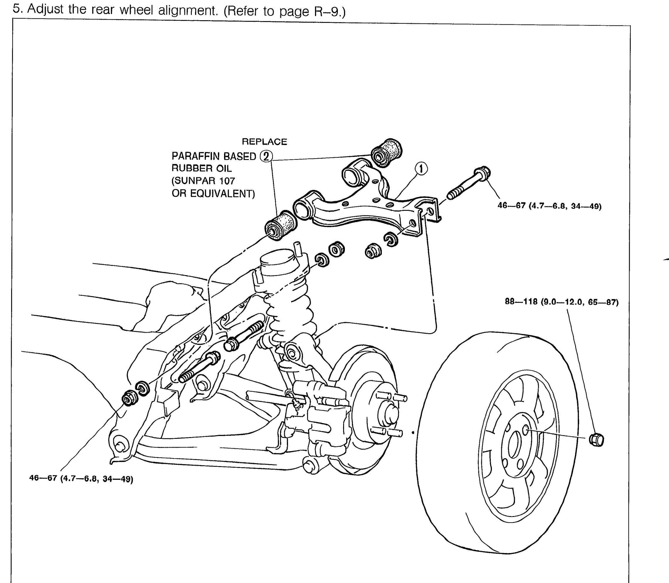
UPPER ARM - Removal / Inspection / Installation
R-24Exploded view of the rear upper arm assembly. Callouts: (1) Upper arm with mounting bolts, (2) Upper arm bushing with REPLACE label and note PARAFFIN BASED RUBBER OIL (SUNPAR 107 OR EQUIVALENT). Torque specs: 46-67 N-m (4.7-6.8 m-kg, 34-49 ft-lb) at upper arm pivot bolts (two locations) and 88-118 N-m (9.0-12.0 m-kg, 65-87 ft-lb) at wheel nut.
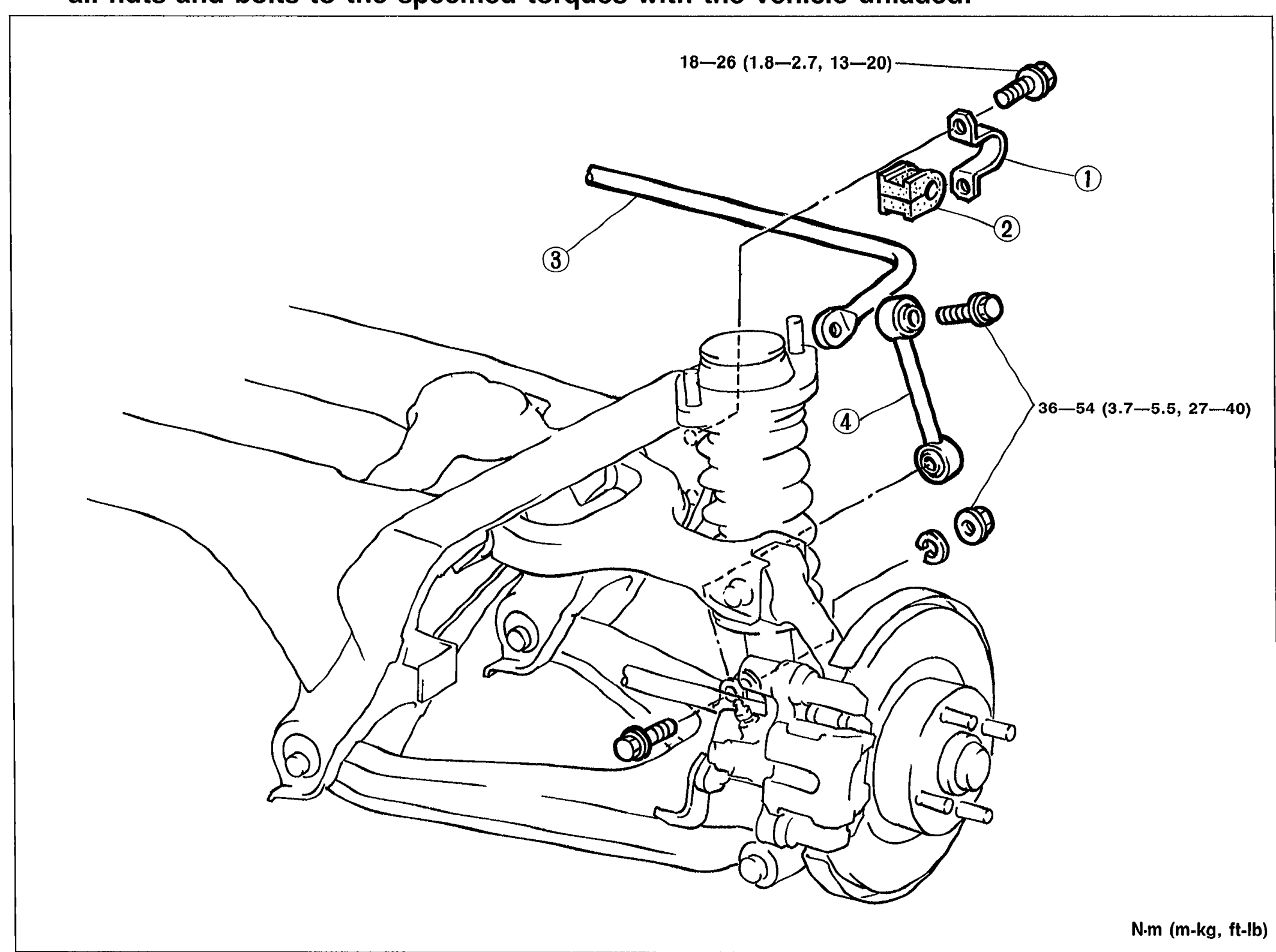
STABILIZER - Removal / Inspection / Installation
R-25Exploded view of the rear stabilizer (sway-bar) assembly. Numbered callouts: (1) Stabilizer bracket, (2) Stabilizer bushing, (3) Stabilizer (bar), (4) Control link. Torque values shown: 18-26 N-m (1.8-2.7 m-kg, 13-20 ft-lb) at bracket bolt; 36-54 N-m (3.7-5.5 m-kg, 27-40 ft-lb) at control link bolts.
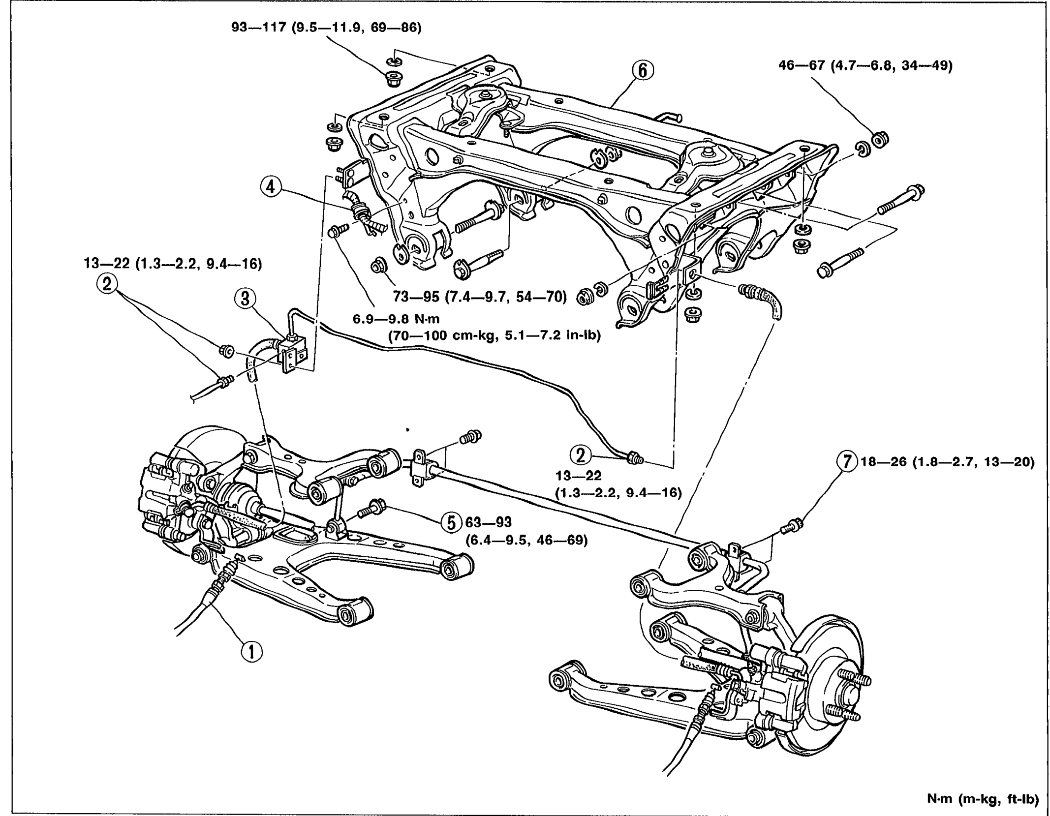
CROSSMEMBER - Removal / Inspection / Installation
R-26Exploded view of the rear crossmember assembly with surrounding components. Numbered callouts: (1) Parking brake cable, (2) Brake pipe, (3) Brake pipe joint, (4) Battery cable bracket, (5) Shock absorber bolt, (6) Rear crossmember assembly, (7) Stabilizer bracket, (8) Upper arm bolt, (9) Lower arm bolt. Torque specs in N-m (m-kg, ft-lb): 93-117 (9.5-11.9, 69-86) at crossmember mount, 46-67 (4.7-6.8, 34-49) upper arm bolt, 13-22 (1.3-2.2, 9.4-16) brake pipe clips (two locations), 73-95 (7.4-9.7, 54-70), 6.9-9.8 N-m (70-100 cm-kg, 5.1-7.2 in-lb) at brake pipe joint, 18-26 (1.8-2.7, 13-20) stabilizer bracket, 63-93 (6.4-9.5, 46-69) shock absorber bolt.
Body
S24 diagrams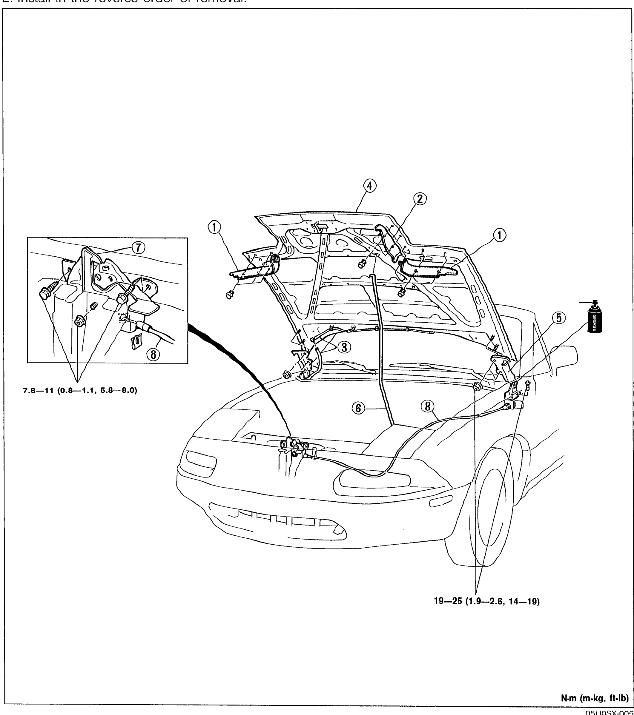
HOOD
S-5Exploded view of the hood assembly showing the hood lock (callout 7) at top-left in a detail circle, the hood panel with hinges, headlight seal, side headlight seal, washer pipe, hood stay, and release wire callouts numbered 1-8. Torque specs shown: 7.8-11 N·m (0.8-1.1 m-kg, 5.8-8.0 ft-lb) for the hood lock area, and 19-25 N·m (1.9-2.6 m-kg, 14-19 ft-lb) for the hinge area. Vehicle drawn from front-left perspective with hood open.
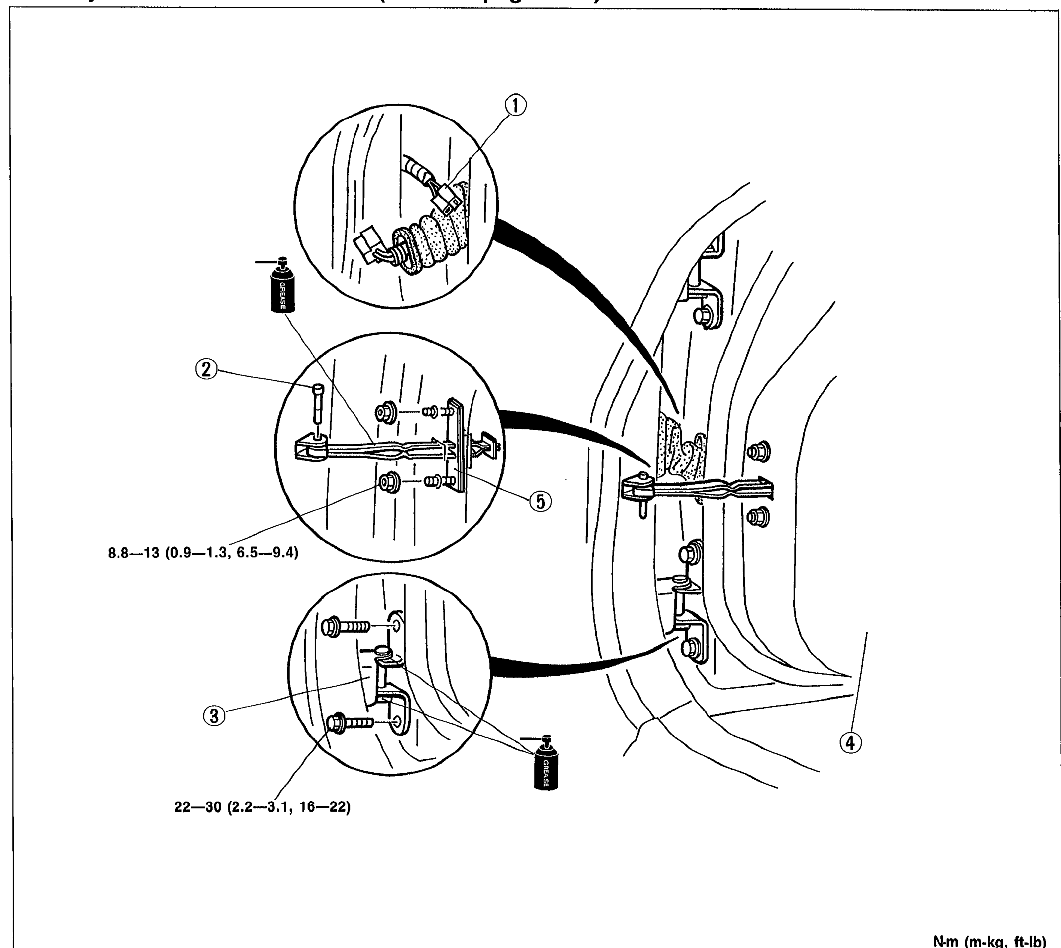
DOOR
S-7Exploded view of the MX-5 door assembly with three circular detail insets showing: harness connector (callout 1, top), checker pin and checker mechanism (callouts 2 and 5, middle) with torque 8.8-13 N·m (0.9-1.3 m-kg, 6.5-9.4 ft-lb), and hinge (callout 3, bottom) with torque 22-30 N·m (2.2-3.1 m-kg, 16-22 ft-lb). The door (callout 4) is shown attached to body.
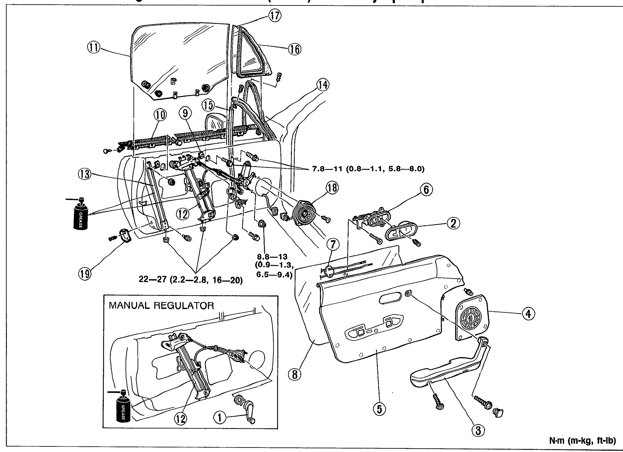
WINDOW REGULATOR, GLASS, AND GUIDE
S-9Exploded view of the MX-5 door internals including window regulator, door glass, quarter glass, weatherstrips, division channel, sealing pad, door screen, beltline molding, inner handle, door trim, arm rest, speaker grille and dovetail. Inset shows MANUAL REGULATOR with regulator handle (callout 1). Numbered callouts 1-19. Torque callouts: 7.8-11 N·m (0.8-1.1 m-kg, 5.8-8.0 ft-lb), 22-27 N·m (2.2-2.8 m-kg, 16-20 ft-lb), and 8.8-13 N·m (0.9-1.3 m-kg, 6.5-9.4 ft-lb).
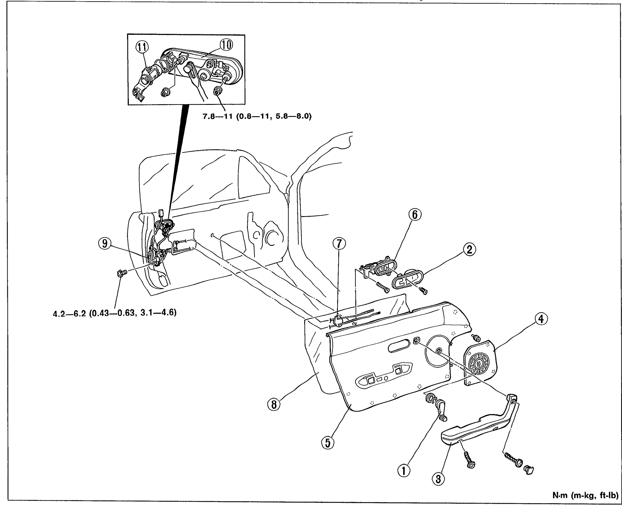
DOOR LOCK AND OPENER
S-15Exploded view of the door interior showing 11 numbered callouts pointing to door lock and opener components: regulator handle (1), inner handle cover (2), armrest (3), speaker grille (4), door trim (5), inner handle (6), sealing pad (7), door screen (8), door lock assembly (9), outer handle (10), key cylinder (11). Two torque-spec tags are shown: '7.8-11 (0.8-11, 5.8-8.0)' near the upper lock mechanism inset and '4.2-6.2 (0.43-0.63, 3.1-4.6)' near the door lock assembly. Units are N·m (m-kg, ft-lb).
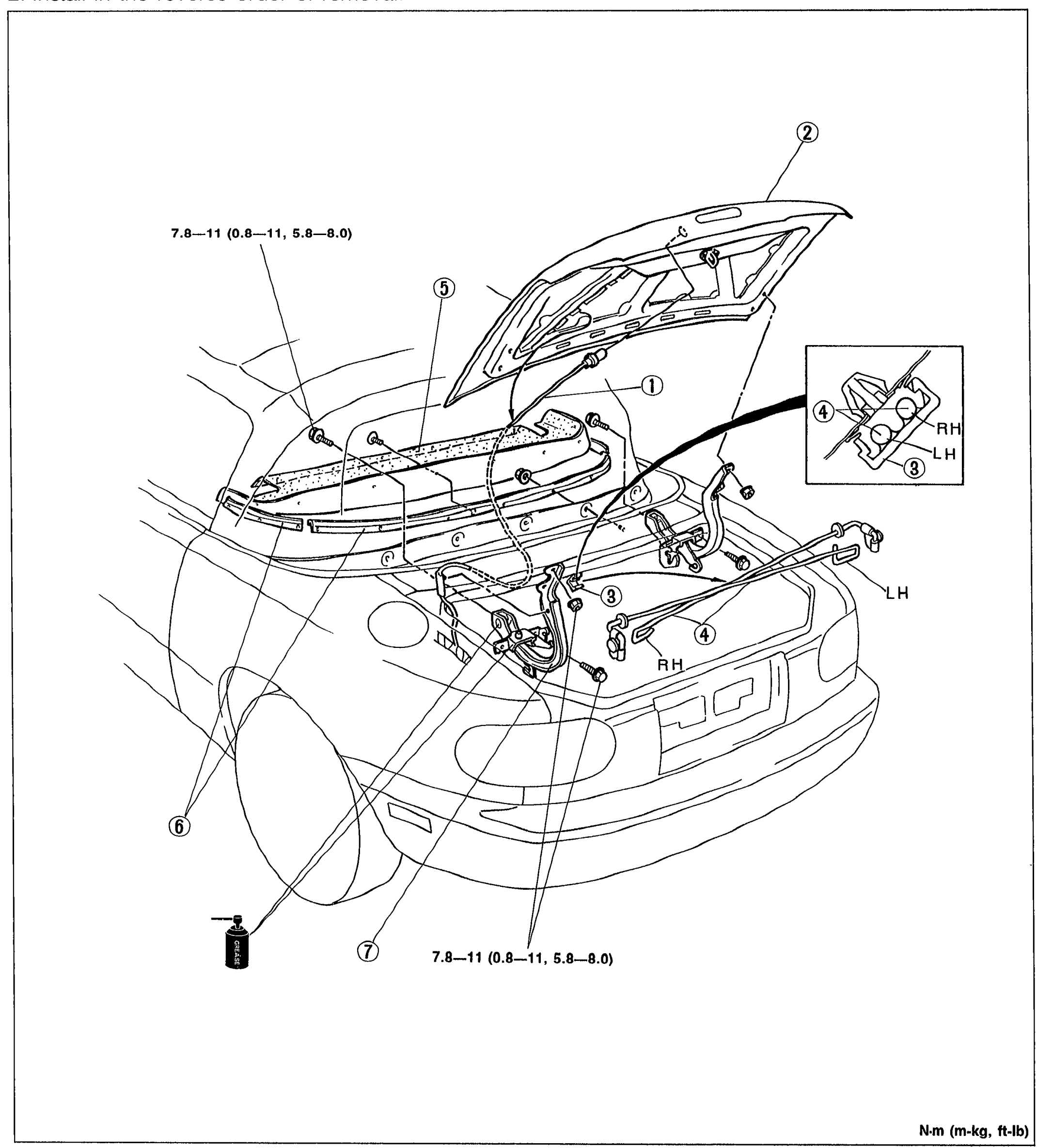
TRUNK LID
S-16Exploded rear-three-quarter view of the trunk lid showing 7 numbered callouts: wire harness (1), trunk lid (2), rod holder (3), balance spring (4) with separate LH/RH inset, rear package trim (5), set plate (6), hinge (7). LH/RH labels mark left-hand and right-hand assemblies. Two torque-spec tags read '7.8—11 (0.8—11, 5.8—8.0)' in N·m (m-kg, ft-lb).
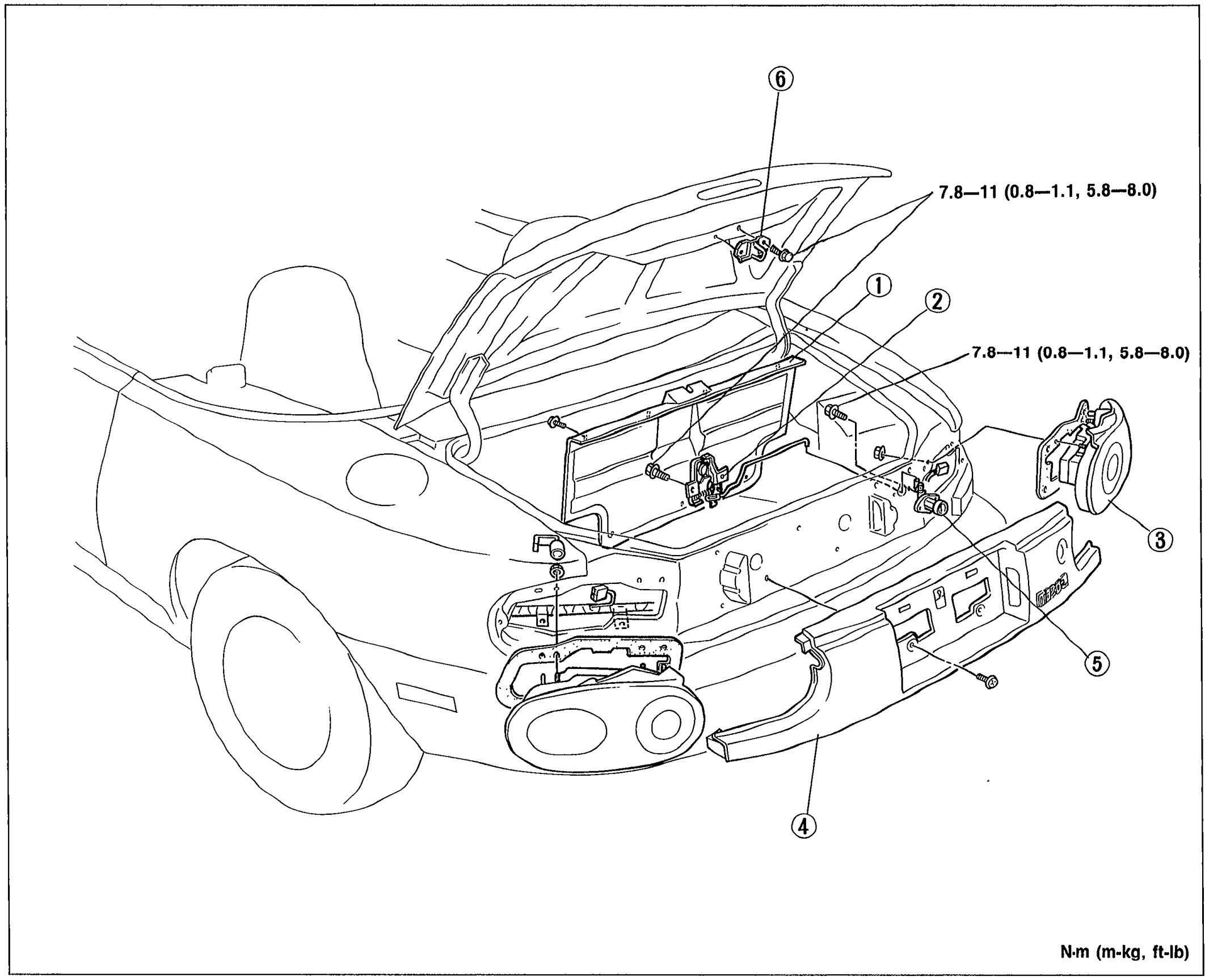
TRUNK LID LOCK AND OPENER
S-18Rear-three-quarter exploded view of the trunk lid lock and opener showing 6 numbered callouts: trunk end trim (1), trunk lid lock assembly (2), rear combination light (3), rear finisher (4), key cylinder (5), striker (6). Two torque-spec tags both read '7.8—11 (0.8—1.1, 5.8—8.0)' in N·m (m-kg, ft-lb).
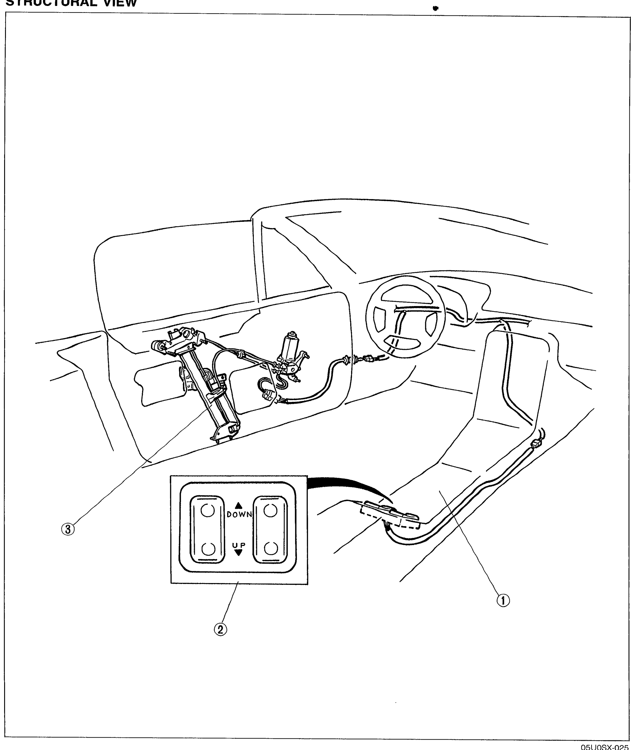
POWER WINDOW SYSTEM
S-19Cut-away interior view of the MX-5 cabin from the driver's side showing the power window system structural layout. Three numbered callouts: rear console (1) at the center tunnel, power window main switch (2) (depicted as a rocker switch with UP and DOWN arrows), and power window regulator (3) inside the driver's door. Steering wheel and dashboard are visible for orientation.
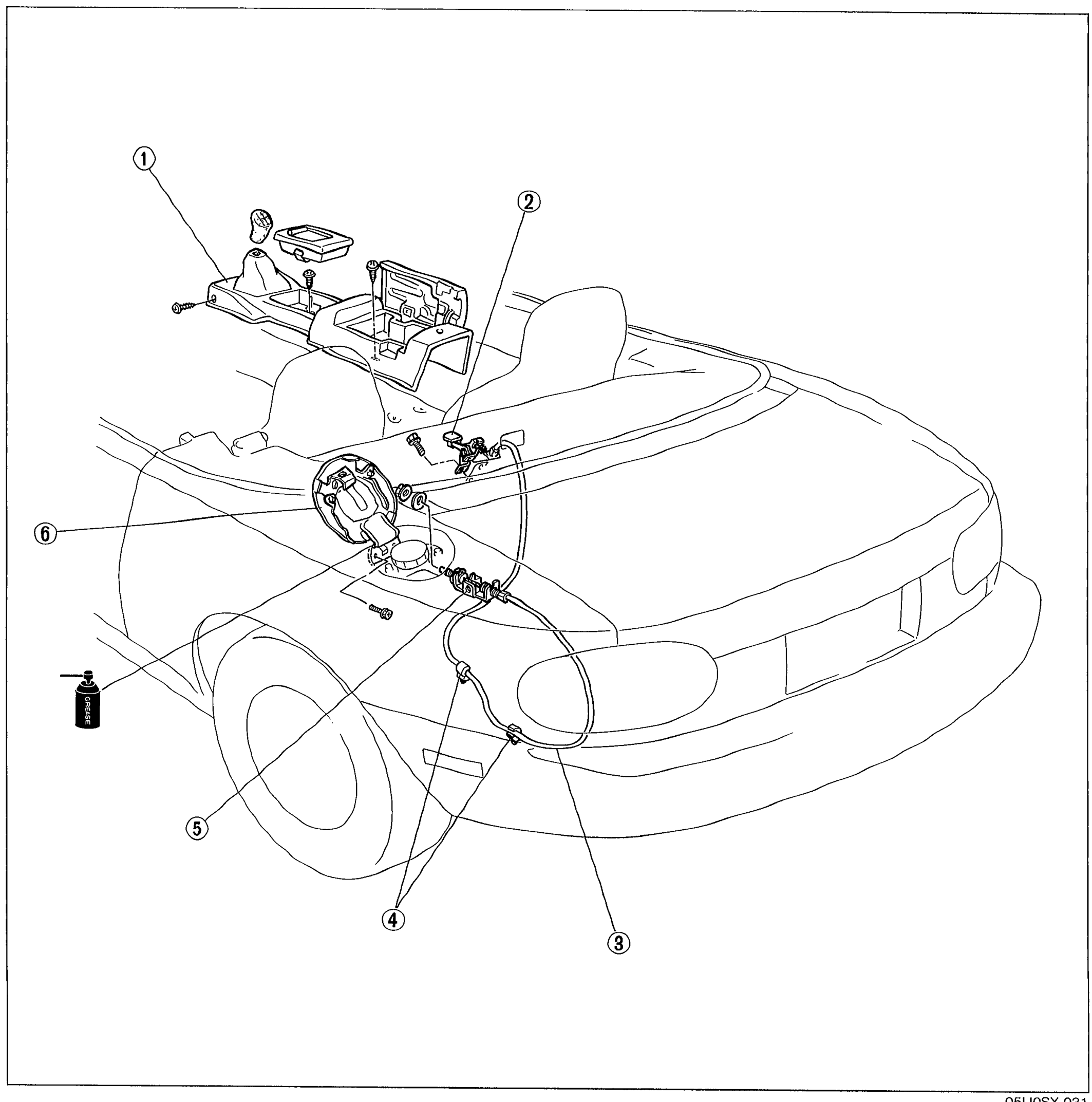
FUEL FILLER LID OPENER
S-23Three-quarter cutaway view of the MX-5 rear showing the fuel filler lid opener cable routing. Six numbered callouts: rear console (1) at the interior, opener lever (2) inside the console, opener cable (3) running back through the body, clip (4) securing the cable, filler lid opener (5) at the fuel filler neck, filler lid (6) on the body panel.
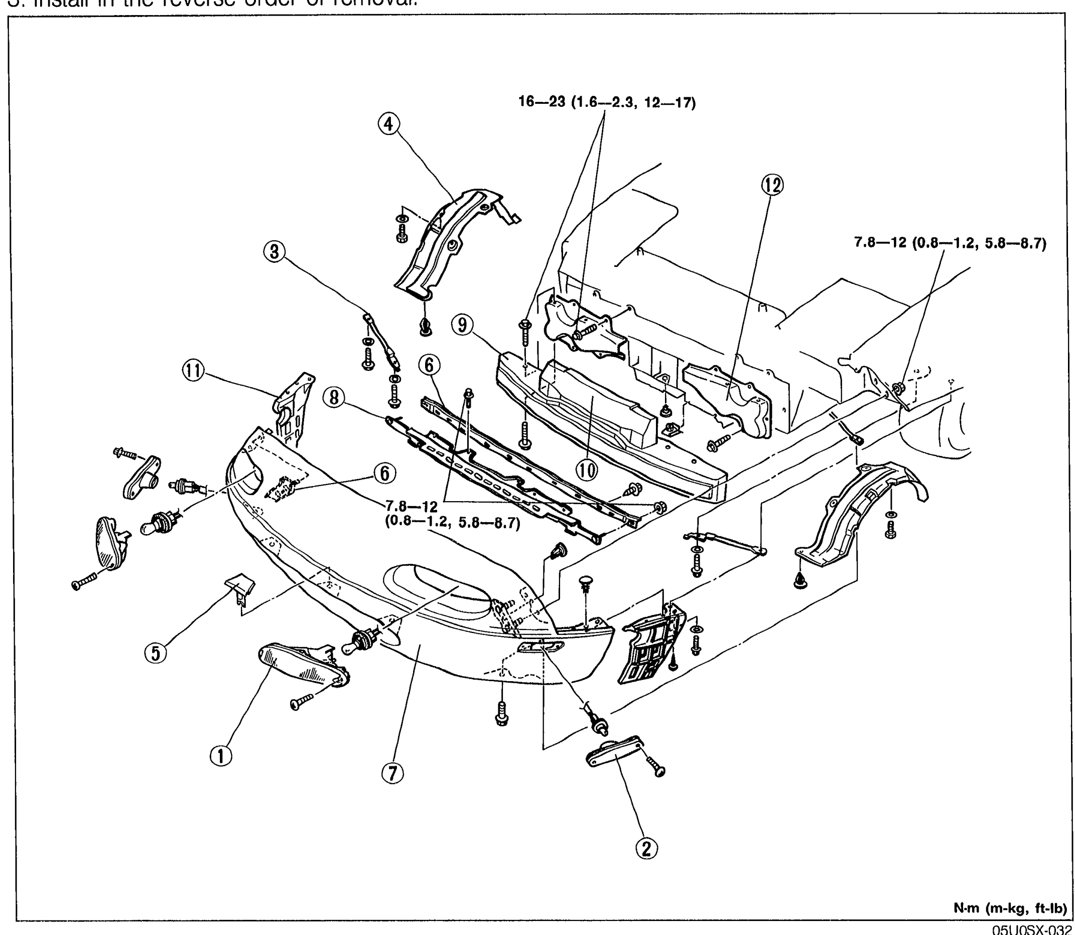
FRONT BUMPER
S-24Exploded front-three-quarter view of the MX-5 front bumper and surrounding components. Twelve numbered callouts: front combination light (1), front side marker light (2), fender bracket (3), mud guard (4), grille cover (5), set plate (6), front fascia (7), retainer (8), bumper reinforcement (9), spacer (10), front bumper retainer (11), front bumper bracket (12). Two torque-spec tags: '16—23 (1.6—2.3, 12—17)' near the top mount and '7.8—12 (0.8—1.2, 5.8—8.7)' near the lower mount and second tag near front fascia. Units N·m (m-kg, ft-lb).
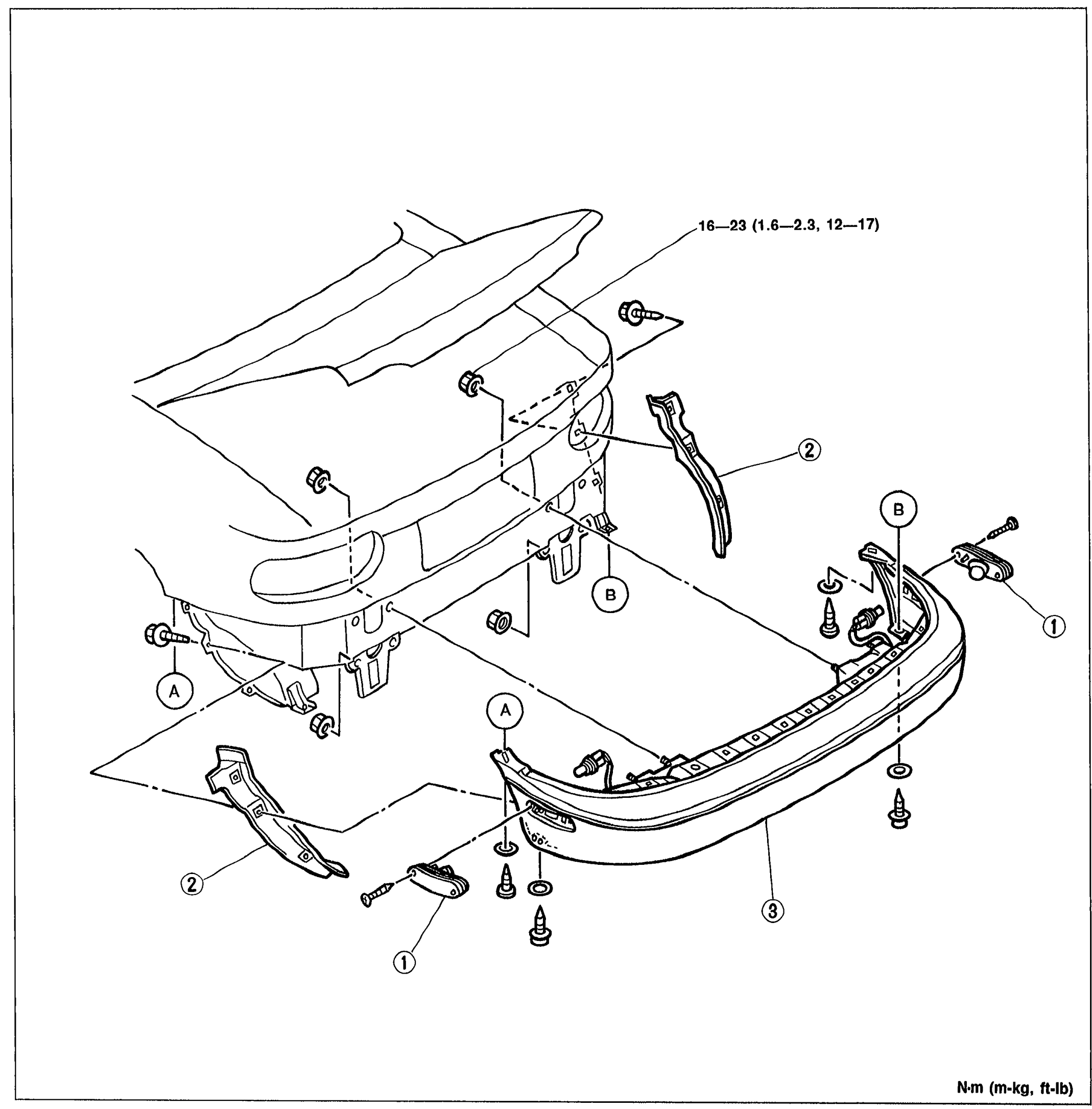
REAR BUMPER
S-25Exploded view of the rear bumper assembly showing the rear of the vehicle with the trunk lid open. Numbered callouts: (1) rear side marker light, (2) splash shield (with bracket), (3) rear bumper. Letter callouts (A) and (B) indicate fastener/bolt locations. Torque specification arrow points to '16-23 (1.6-2.3, 12-17)' N·m at the upper bumper attachment points.
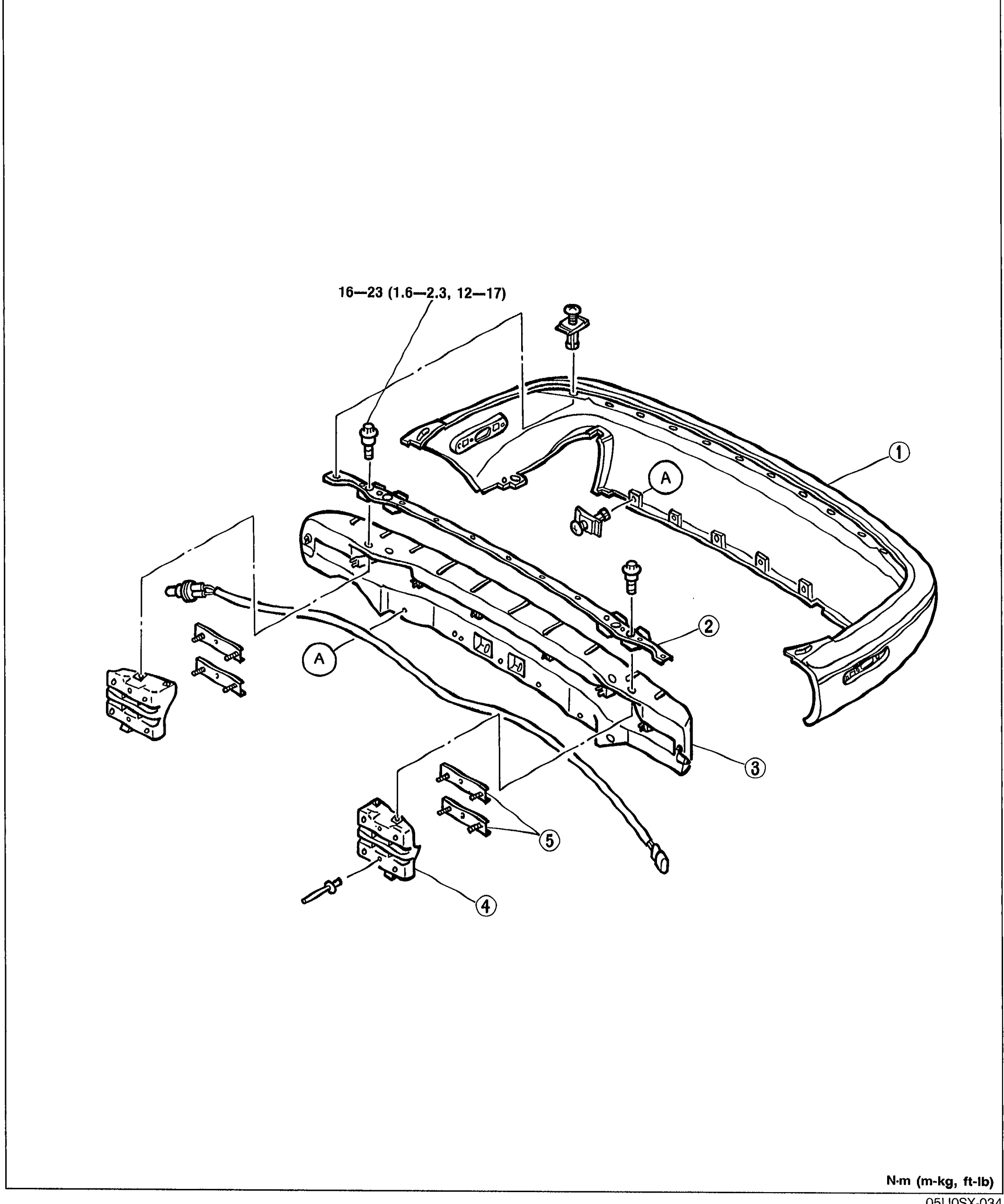
REAR BUMPER
S-26Exploded view of the rear bumper disassembly showing the rear fascia separated from the bumper reinforcement. Numbered callouts: (1) rear fascia, (2) retainer, (3) bumper reinforcement, (4) bumper stay, (5) set plate. Letter callout (A) marks bolt locations. Torque arrow indicates '16-23 (1.6-2.3, 12-17)' for the bumper-stay-to-body bolts.
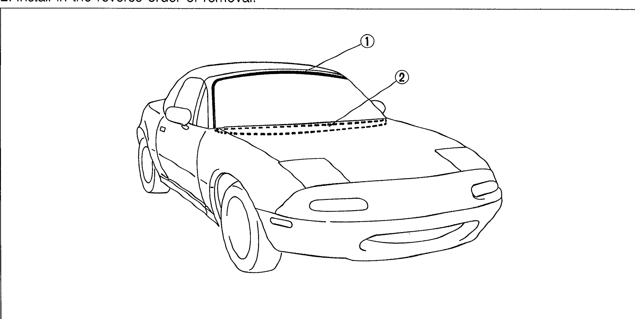
MOLDING AND GARNISH
S-27Front three-quarter view of the MX-5 with hard top, callouts pointing to (1) windshield molding and (2) cowl grille at the front of the vehicle.
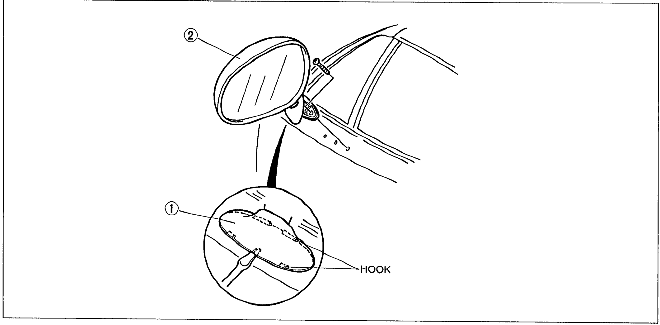
DOOR MIRROR, HORN
S-30Door mirror exploded view showing the rearview mirror (2) attached to the door, with a detail inset bubble showing the mirror cover (1) underside and a 'HOOK' callout pointing to the hook attachment.
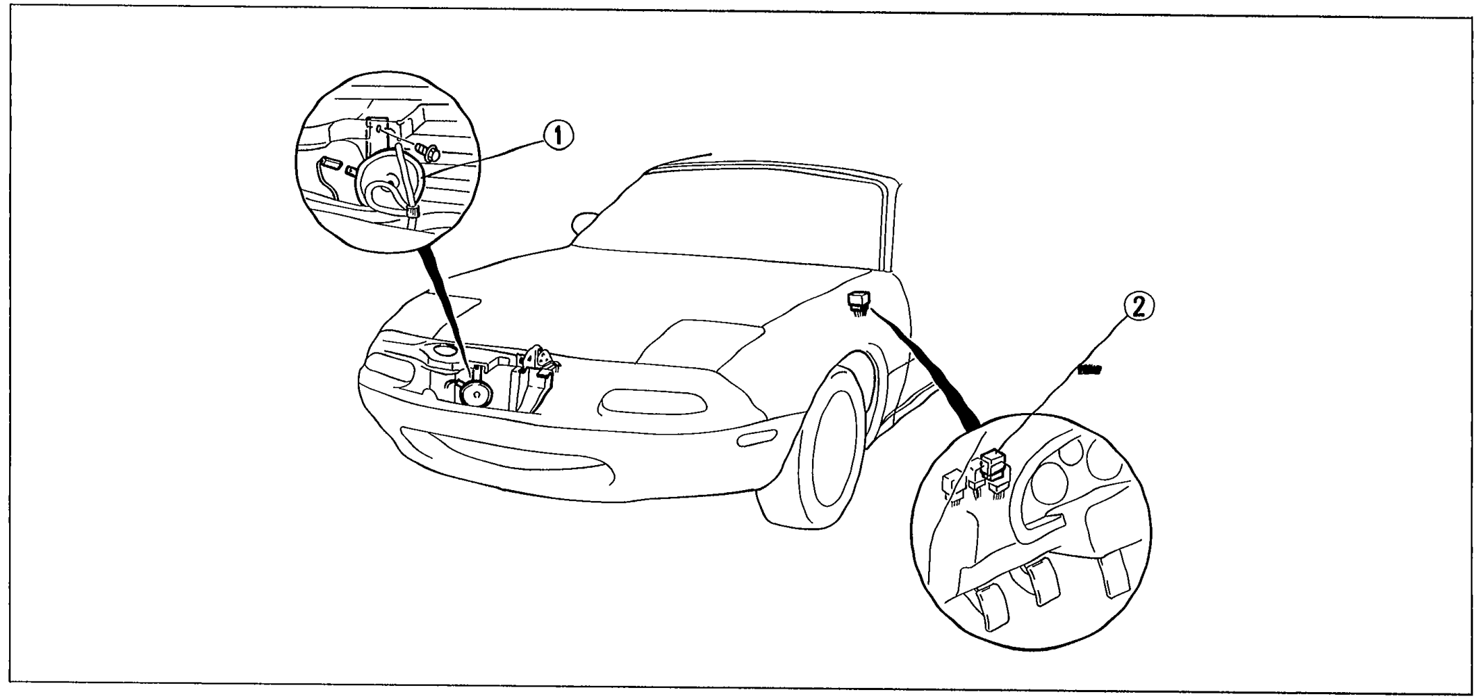
DOOR MIRROR, HORN
S-30Front three-quarter view of the MX-5 showing horn locations. Left inset bubble shows (1) horn mounted behind the front bumper / inside the front fender area. Right inset bubble shows (2) horn relay mounted in the engine bay near the wheel arch.
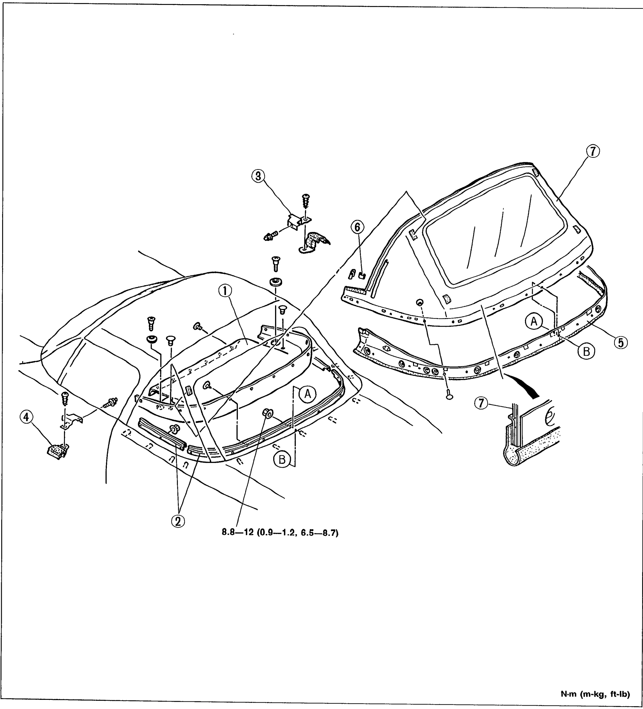
REAR WINDOW (CONVERTIBLE TOP)
S-46Exploded view of the convertible top rear window assembly. Shows numbered balloon callouts 1-7 for: rear package trim, set plate, beltline cover, beltline protector, rain rail, zipper stop, and rear window. Letter callouts A and B mark zipper/seal positions. Tightening torque 8.8-12 N·m (0.9-1.2 m-kg, 6.5-8.7 ft-lb) labeled near hardware.
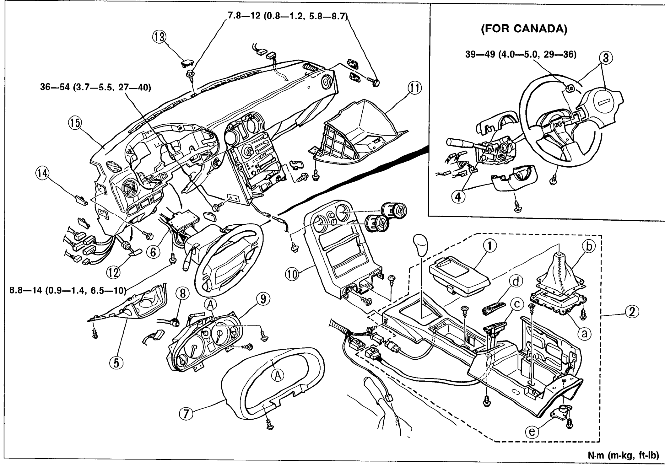
DASHBOARD AND CONSOLE
S-50Exploded view of the dashboard and console assembly with numbered balloon callouts 1-15 covering the ashtray, rear console assembly (with sub-parts a-e), steering wheel/horn cap (Canada), column lower panel (Canada), center lower panel, steering shaft, meter hood, speedometer cable, instrument cluster, center panel, glove box, hood release knob, center hole cover, side cover, and dashboard. An inset labeled (FOR CANADA) shows the steering wheel with torque 39—49 N·m (4.0—5.0, 29—36). Other torques shown: 7.8-12 (0.8-1.2, 5.8-8.7), 36-54 (3.7-5.5, 27-40), 8.8-14 (0.9-1.4, 6.5-10).
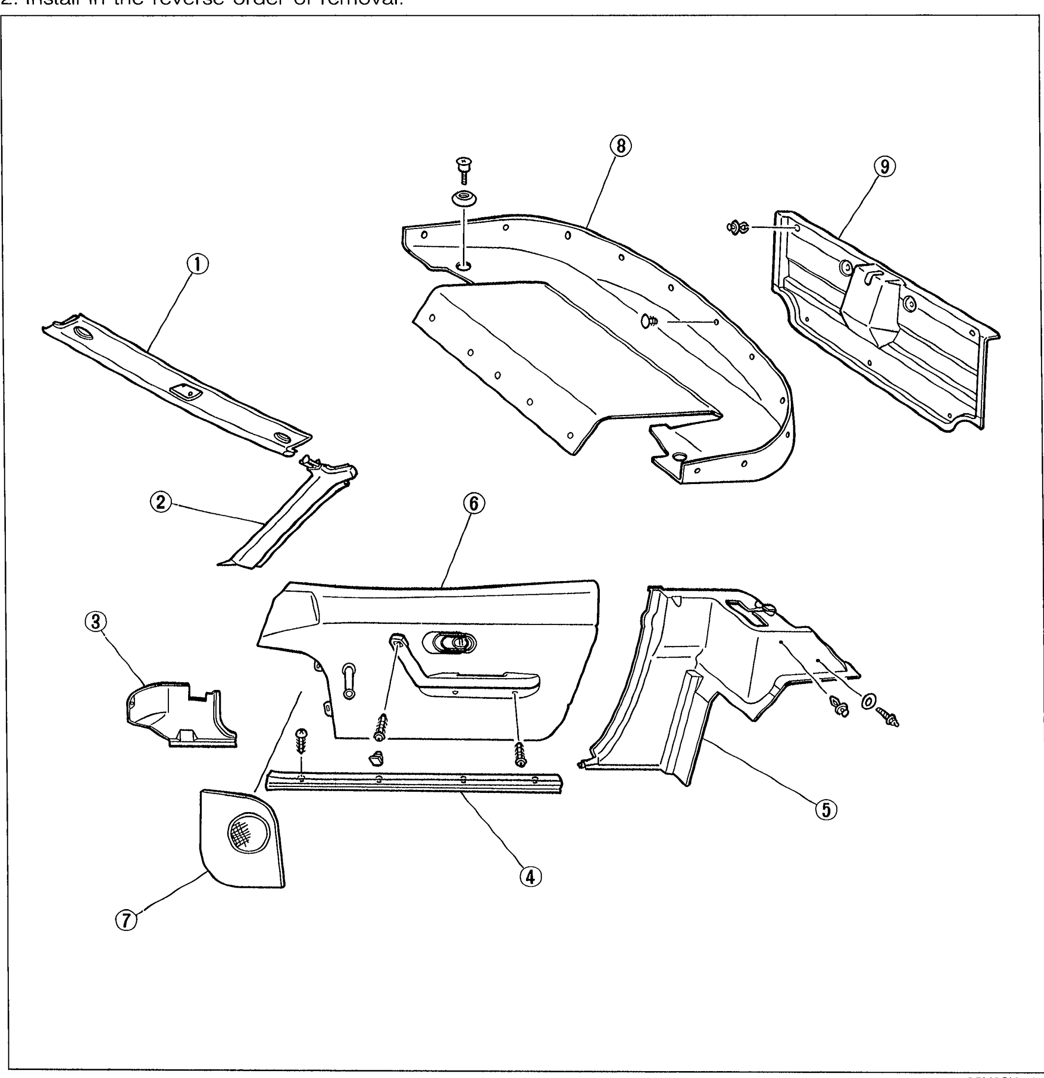
TRIM
S-53Exploded view of interior trim pieces with numbered balloon callouts 1-9: front header trim, A-pillar trim, front side trim, scuff plate, quarter trim, door trim, speaker grille, rear package trim, and trunk end trim. Each part is shown floating apart for clarity.
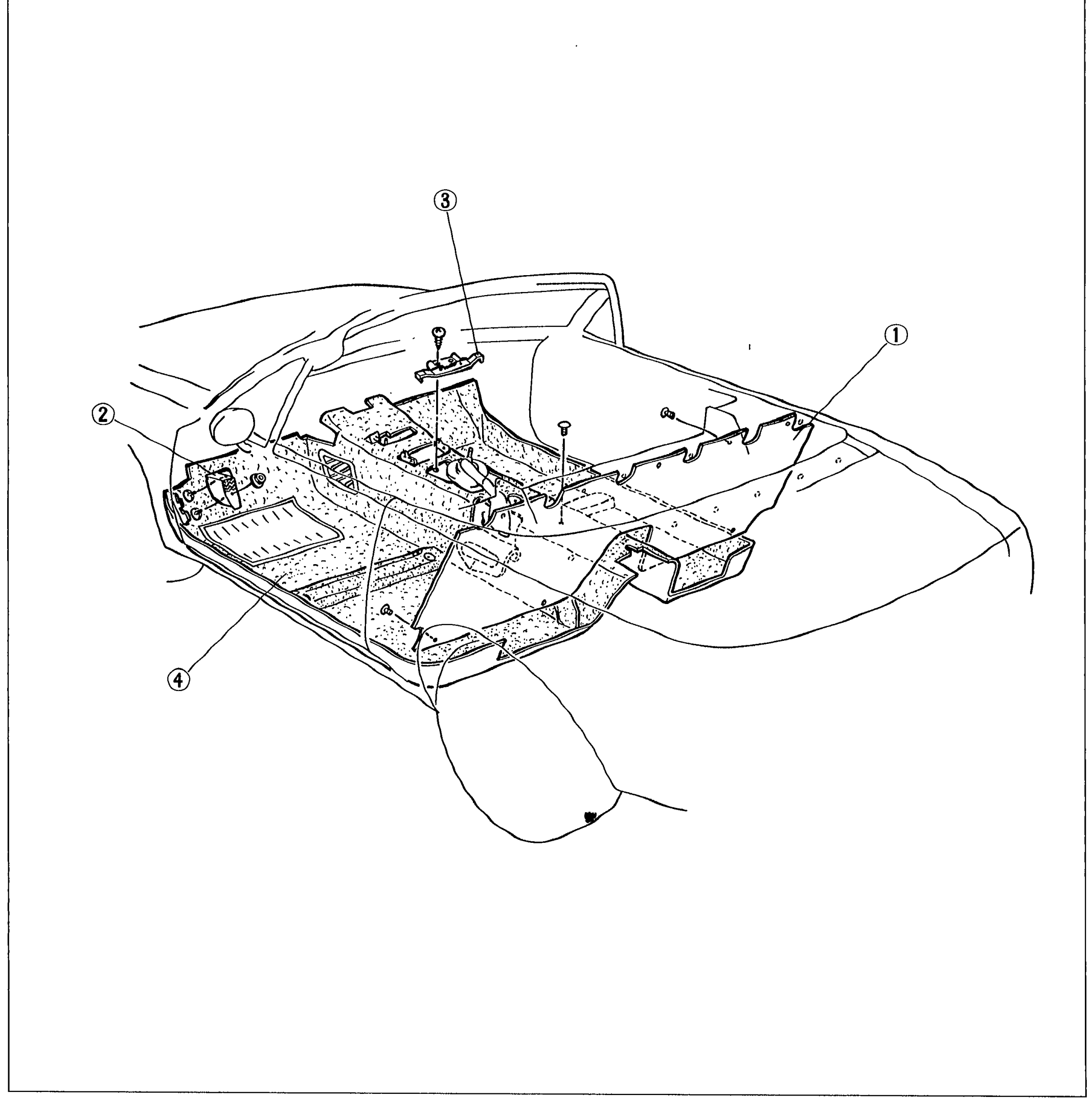
FLOORMAT
S-56Cutaway exploded view of the cabin floor showing the floormat assembly. Numbered callouts: (1) Rear end mat (right side), (2) Foot rest (left side), (3) Bracket (top center), (4) Front floormat (lower left). Drawn from front-right perspective.
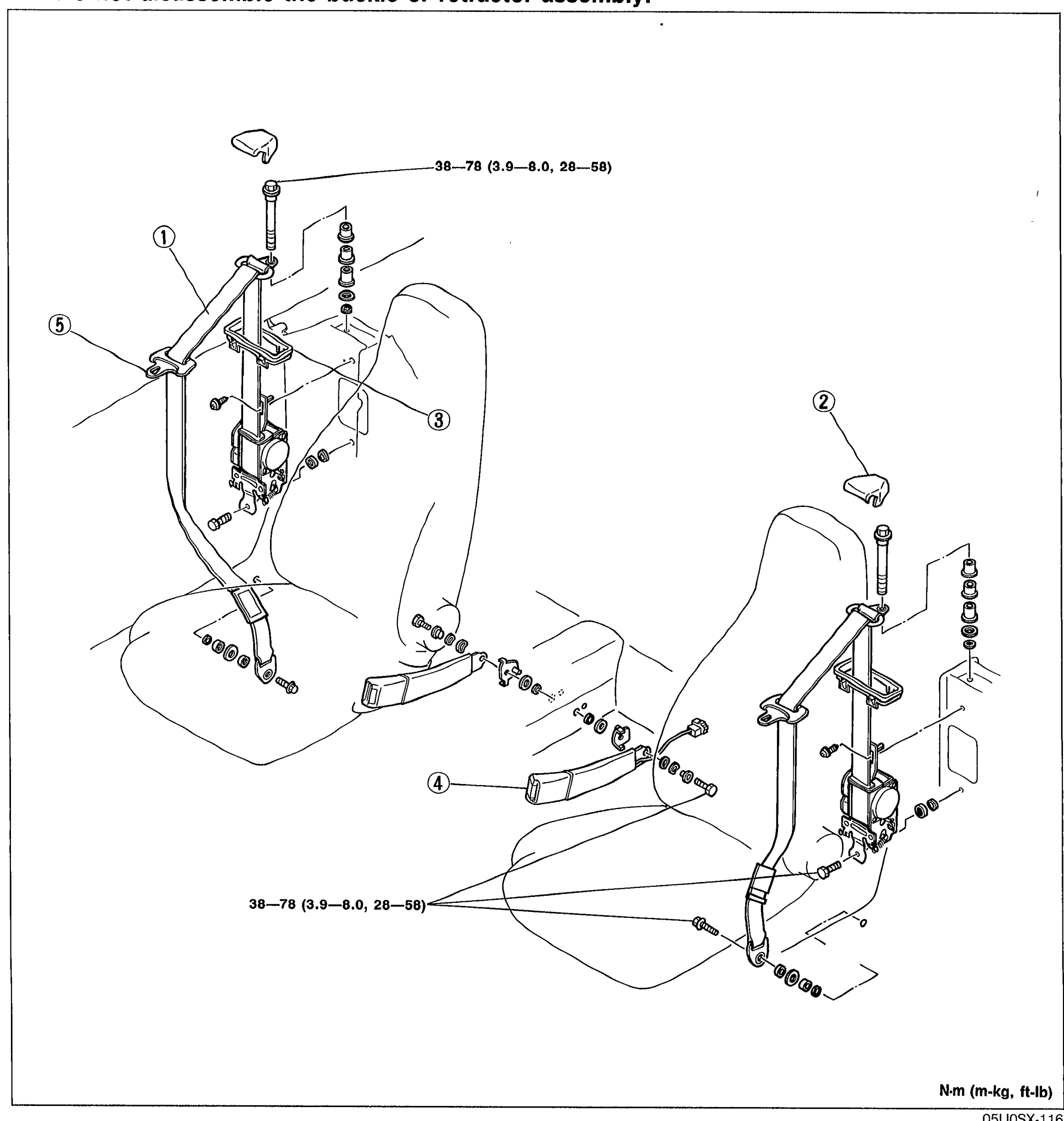
SEAT BELT
S-57Exploded perspective view of the front seats with seat belt assembly. Numbered callouts identify (1) Seat belt, (2) Anchor cover, (3) Bezel, (4) Buckle, (5) Tang. Torque value 38-78 N·m (3.9-8.0 m-kg, 28-58 ft-lb) annotated at upper anchor bolts and lower anchor bolts.
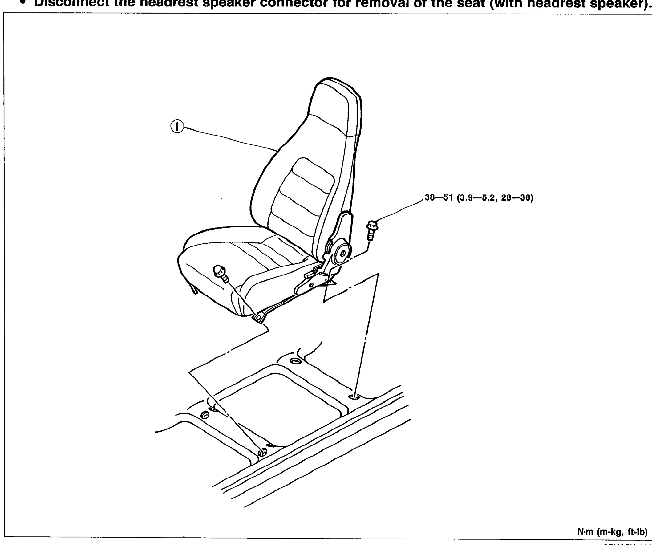
SEAT
S-59Perspective view of the front seat lifted off its rails showing seat (1) Front seat with mounting bolts. Torque value 38-51 N·m (3.9-5.2 m-kg, 28-38 ft-lb) annotated at the mounting points.
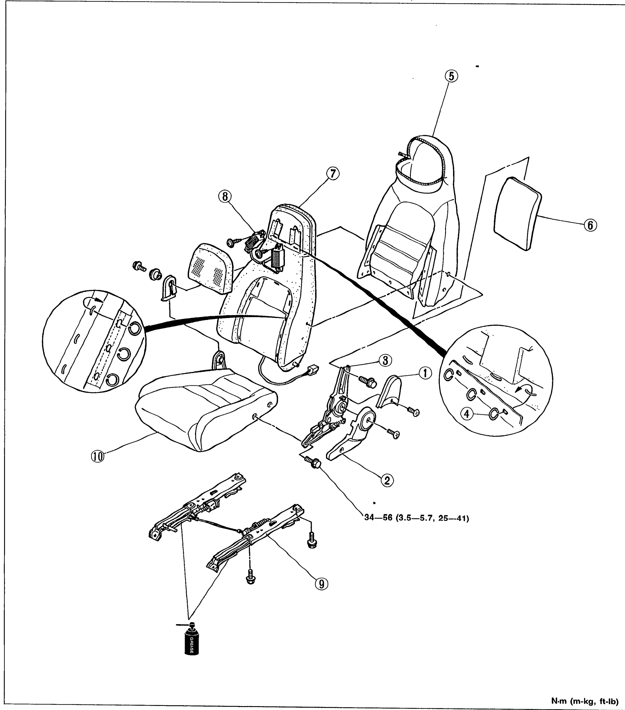
SEAT
S-60Exploded view of the front seat showing disassembly order. Numbered callouts: (1) Side cover, (2) Reclining knuckle cover, (3) Reclining knuckle, (4) Hog ring, (5) Seatback trim, (6) Pad, (7) Back frame, (8) Headrest speaker, (9) Seat slide, (10) Seat cushion. Torque value 34-56 N·m (3.5-5.7, 25-41) annotated near reclining knuckle (2).
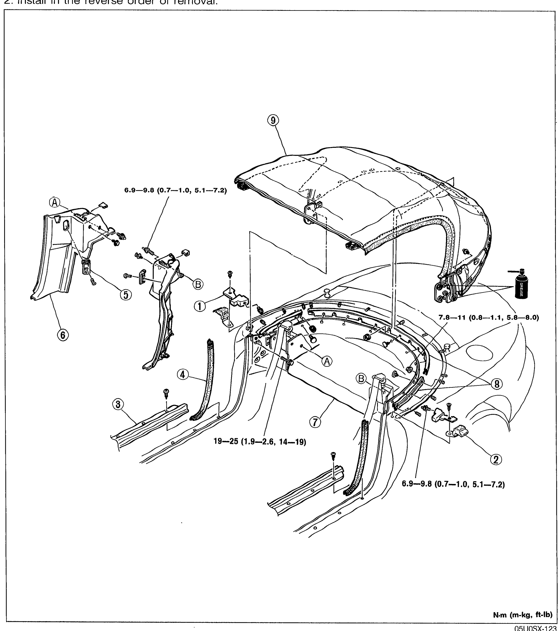
CONVERTIBLE TOP
S-61Exploded perspective view of the convertible top assembly. Numbered callouts: (1) Beltline cover, (2) Beltline protector, (3) Scuff plate, (4) Seaming welt, (5) Striker, (6) Quarter trim, (7) Rear package trim, (8) Set plate, (9) Convertible top. Letter callouts A and B indicate alignment/positioning points. Torque values annotated: 6.9-9.8 N·m (0.7-1.0 m-kg, 5.1-7.2 ft-lb) at upper-left and lower; 7.8-11 (0.8-1.1, 5.8-8.0) at right (set plate); 19-25 (1.9-2.6, 14-19) at scuff plate.
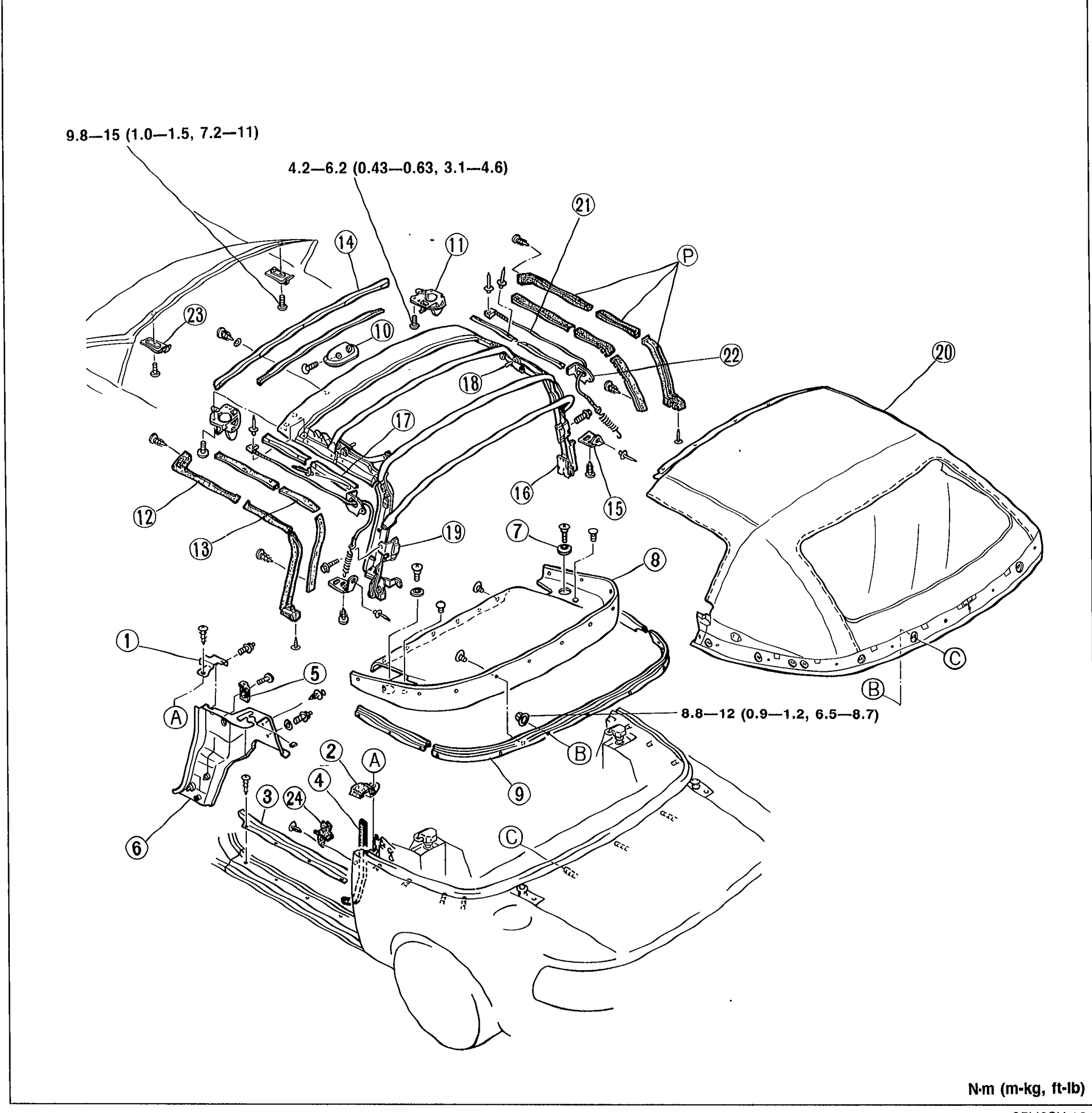
CONVERTIBLE TOP
S-62Large exploded view of the convertible top assembly showing the cabin, the soft-top frame, and the top fabric. 24 numbered callouts plus letter-coded alignment marks A, B, C. Torque values annotated: 9.8-15 N·m (1.0-1.5, 7.2-11), 4.2-6.2 (0.43-0.63, 3.1-4.6), and 8.8-12 (0.9-1.2, 6.5-8.7).
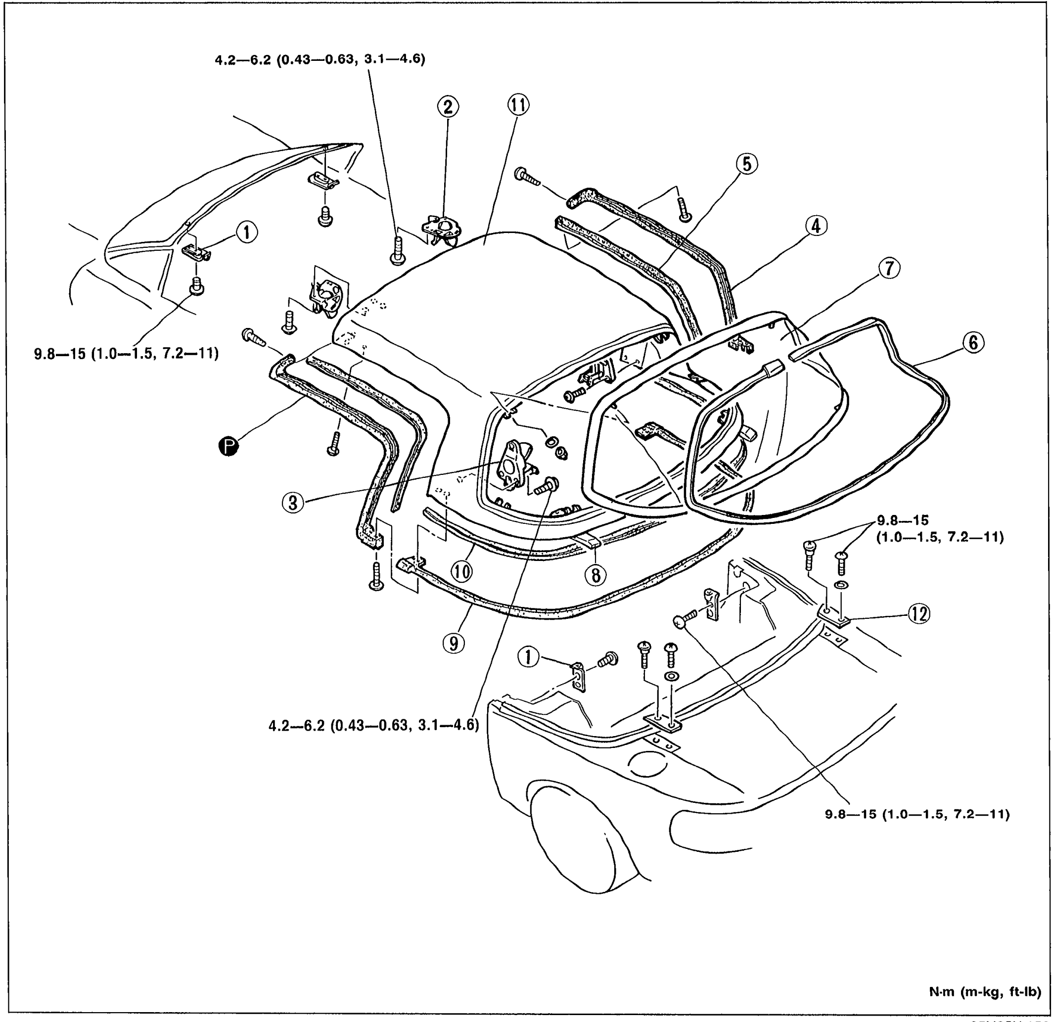
DETACHABLE HARD TOP
S-70Exploded view of the DETACHABLE HARD TOP showing the hard top shell, rear window glass, weatherstrips, latch assemblies, retainers, and mounting hardware. Numbered balloon callouts 1–12 identify components. Torque specifications are noted at fasteners: 4.2—6.2 N·m (0.43—0.63 m-kg, 3.1—4.6 ft-lb) and 9.8—15 N·m (1.0—1.5, 7.2—11). Torque units footer: N·m (m-kg, ft-lb).
Body Electrical System
T3 diagrams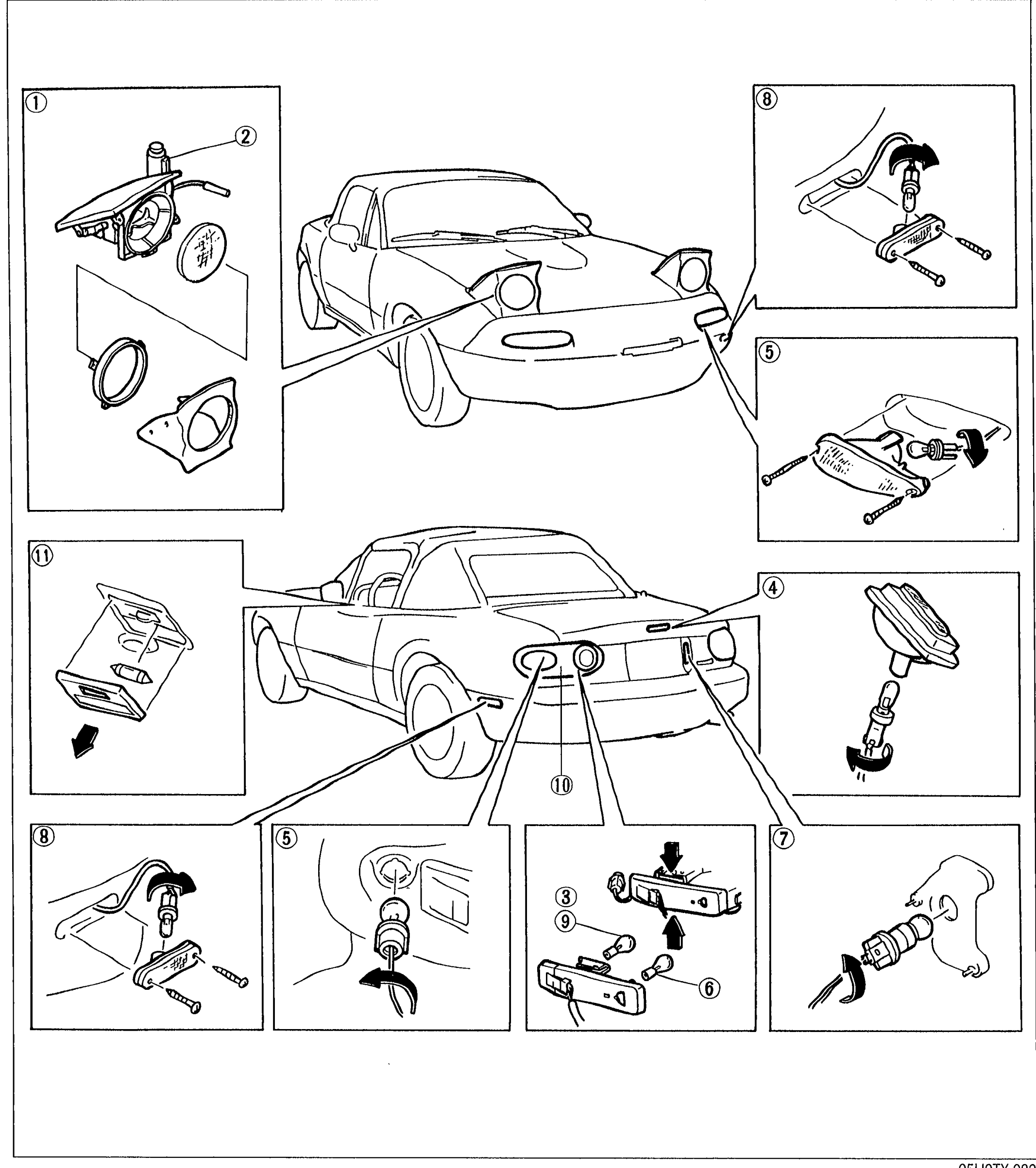
LIGHTING SYSTEM
T-44Structural view of the MX-5 lighting system. Front three-quarter vehicle illustration (top) with numbered callouts 1 (retractable headlight), 2 (headlight retractor motor), 5 (turn and hazard warning light), 8 (side marker light); rear three-quarter illustration (bottom) with callouts 4 (high-mount stoplight), 8, 5, 3/9/6 (stoplight / taillight / back-up light cluster), 7 (license plate light), 10 (rear combination light lens), 11 (interior lamp).
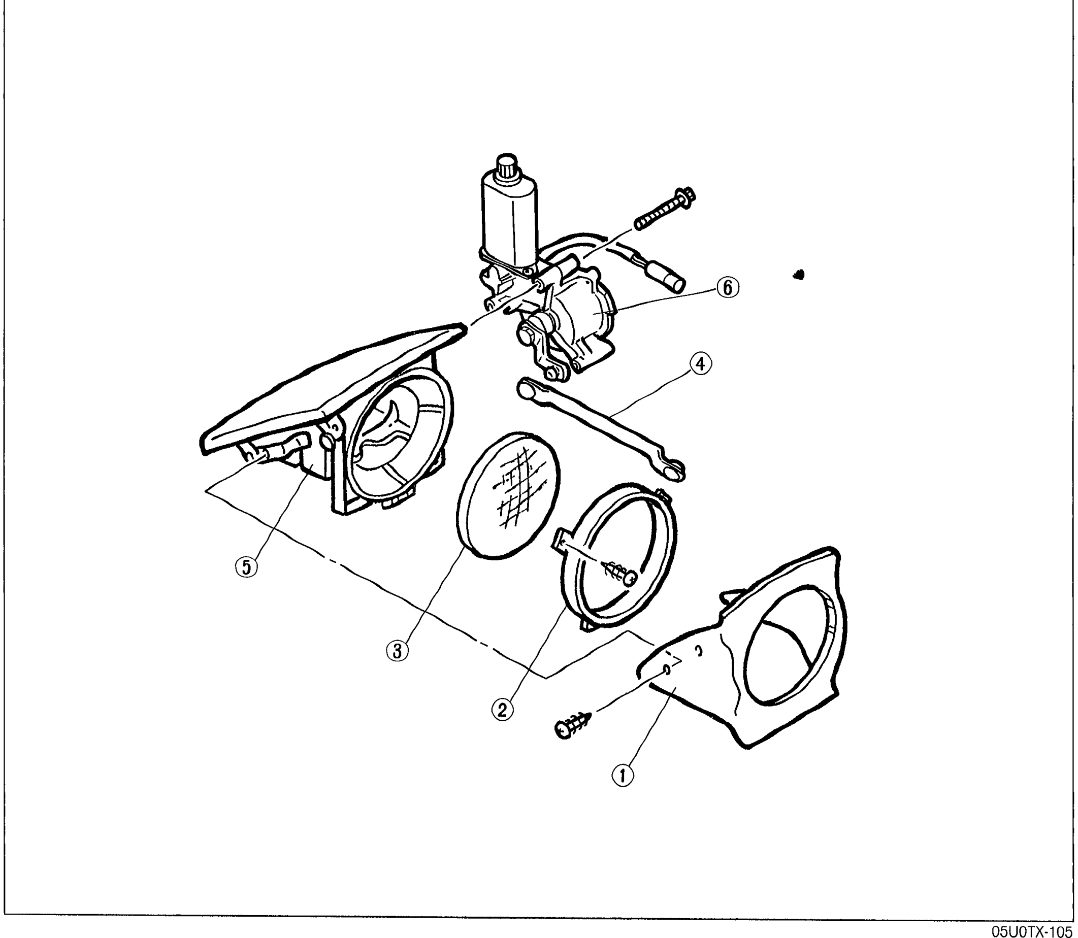
LIGHTING SYSTEM — Removal / Installation (Headlight retractor)
T-54Exploded-view diagram of the headlight retractor assembly. Numbered balloon callouts (1) through (6) identify Bezel, Headlight housing, Headlight (sealed beam), Motor link, Retractor hinge, and Retractor motor. Mounting screws and bolts shown around the assembly.
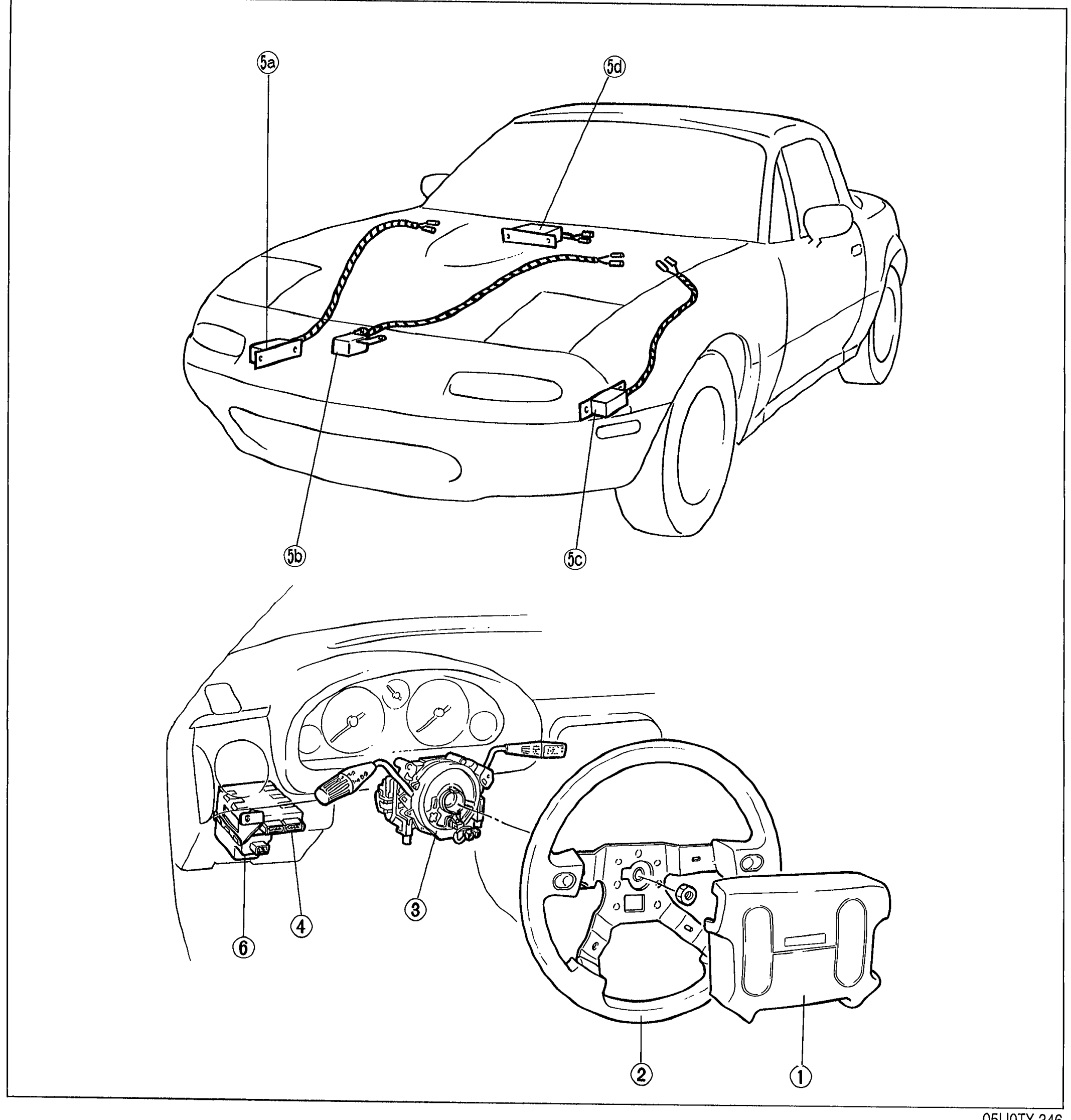
AIR BAG SYSTEM
T-130Structural view of the MX-5 air bag system. Top illustration shows the vehicle exterior with wiring harness routing across the engine bay and to sensors at the front (callouts 5a, 5b/5c, 5d for crush sensors). Bottom illustration shows the interior dashboard area with steering wheel, air bag module (1), steering wheel (2), clock spring connector (3), diagnostic module (4), and backup battery (6).
Heater and Air Conditioner
U14 diagrams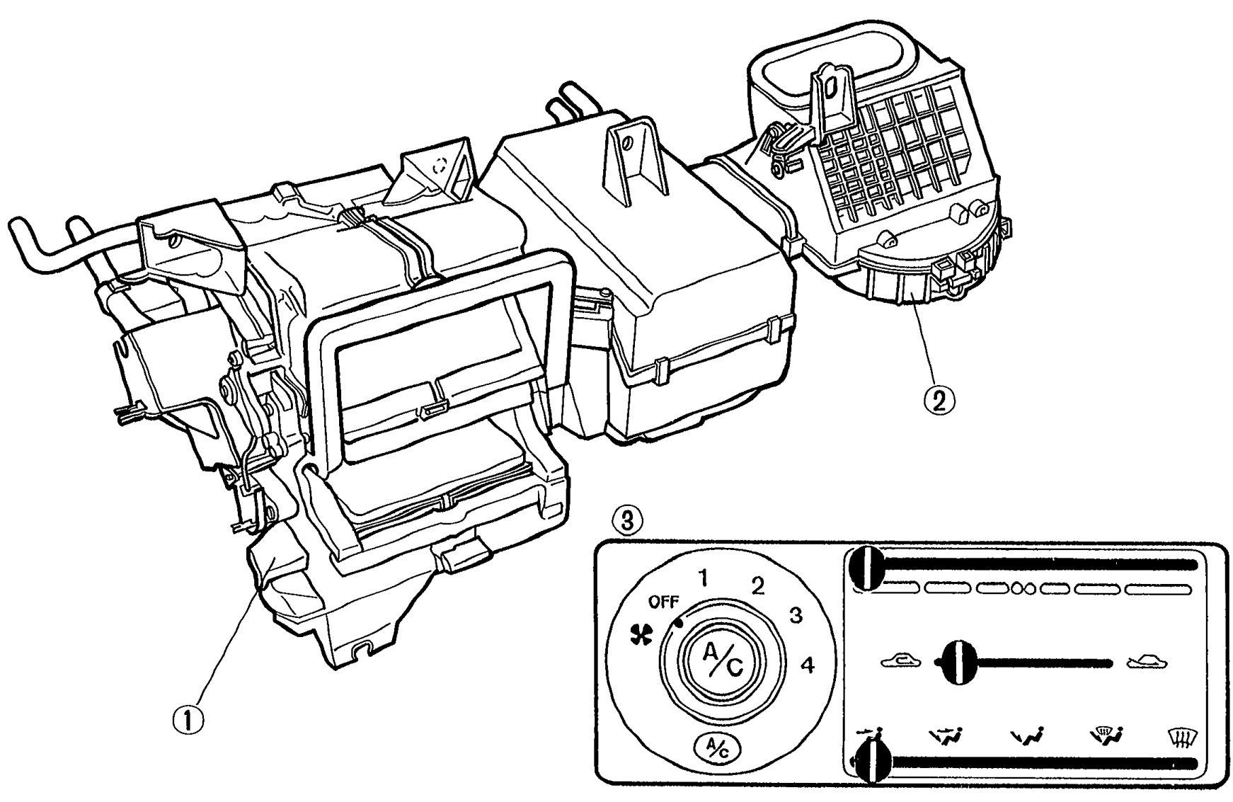
INDEX - HEATER
U-2Exploded/component view of the heater system: heater unit (callout 1) at left, blower unit (callout 2) at upper right, and heater control switch assembly (callout 3) at lower center showing fan switch, mode lever, and temperature lever.
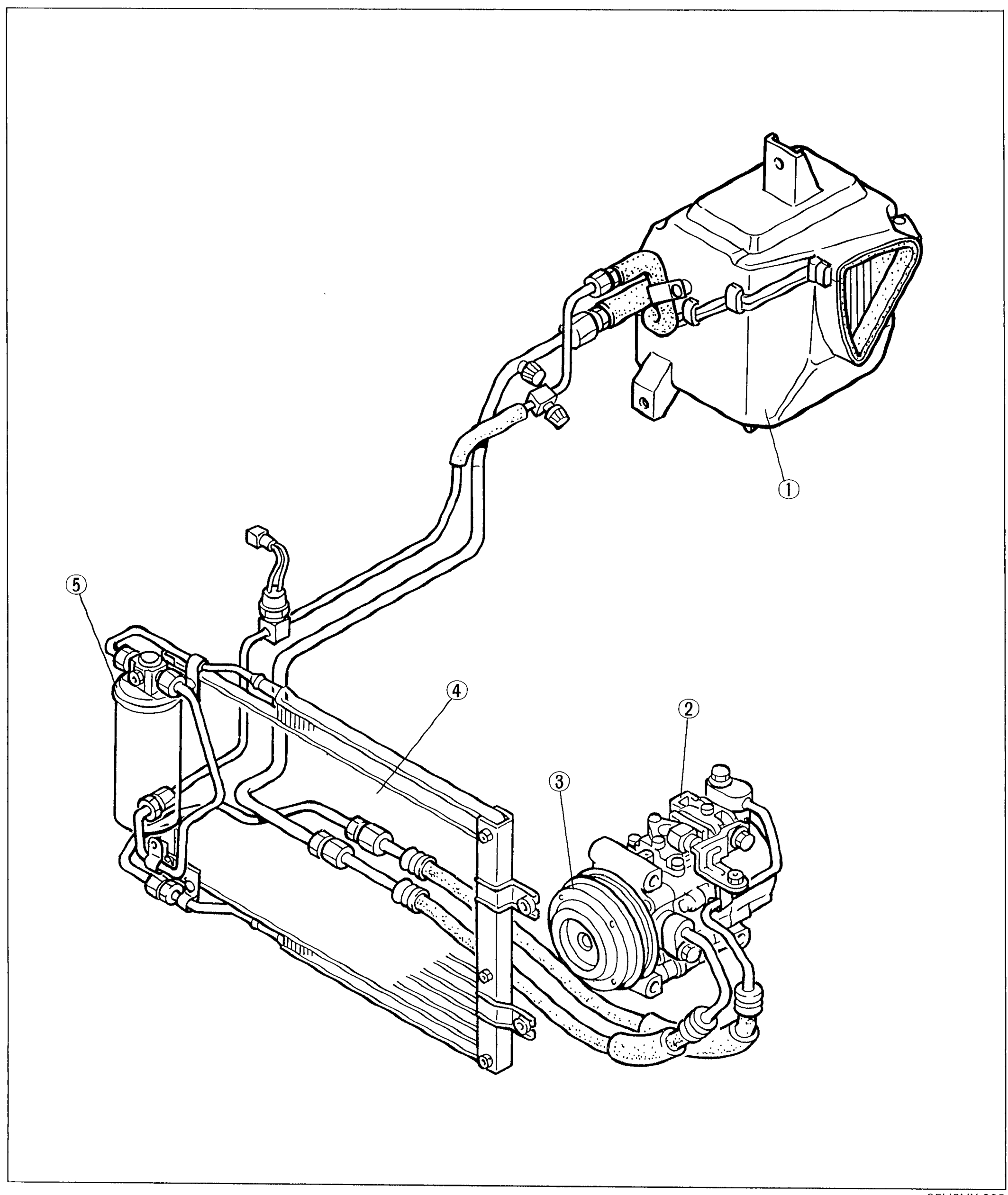
INDEX - AIR CONDITIONER
U-3Exploded view of the air conditioner system showing the cooling unit (callout 1, upper right), compressor (callout 2, center right), magnetic clutch (callout 3, on front of compressor), condenser (callout 4, lower left), and receiver/drier (callout 5, far left) with connecting refrigerant lines.
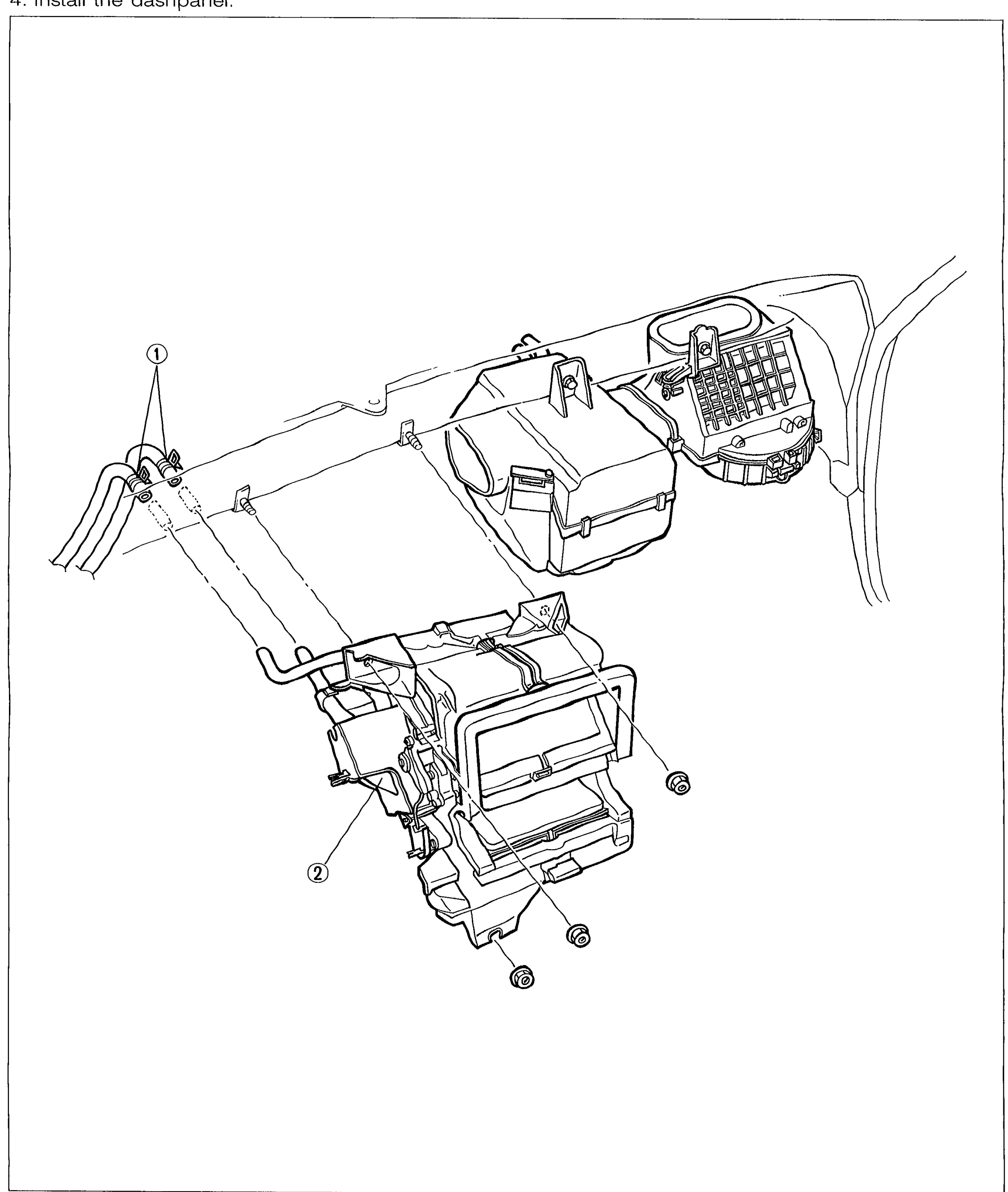
HEATER UNIT
U-19Exploded view of the heater unit installed under the dashpanel. Shows the heater hose connection at the firewall on the left (callout 1), the heater unit core assembly in the centre with bolt locations marked, and the fuse/relay block mounted on the right side. Two numbered callouts identify (1) heater hose at firewall and (2) the heater unit body.
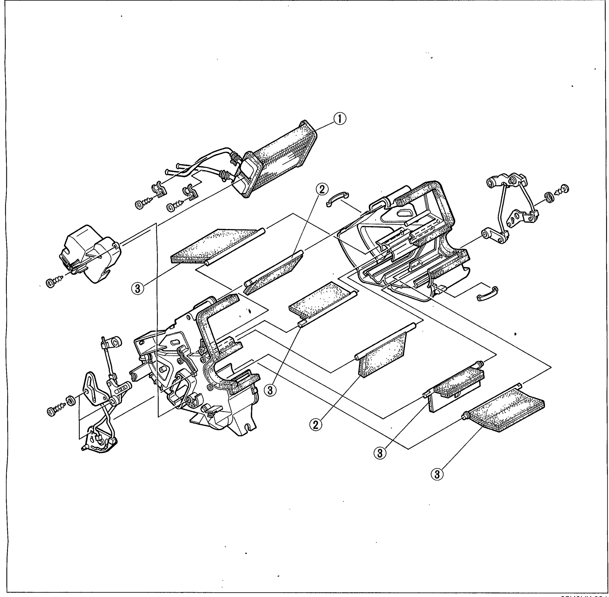
HEATER UNIT
U-20Exploded view of the heater unit showing the heater core (1) at the top, the temperature blend door (2) in the centre, and the airflow mode doors (3) on the sides. Multiple internal foam-edged flap doors and the central case halves are visible, with mounting hardware shown exploded around the assembly.
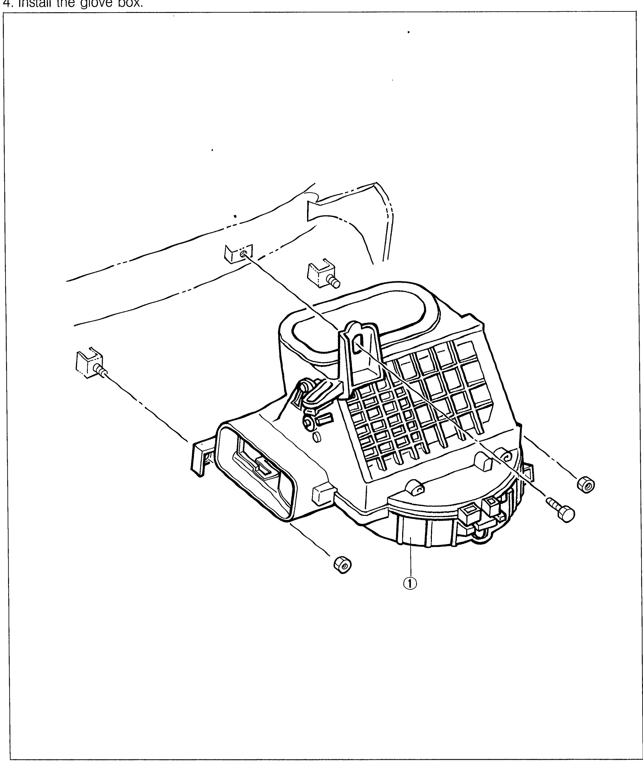
BLOWER UNIT
U-21Exploded view of the blower unit installed behind the dashpanel on the passenger side. Shows the blower housing with its squirrel-cage fan grille, the upper mounting bracket clip, and the lower retaining bolts. Callout 1 points to the complete blower unit assembly.
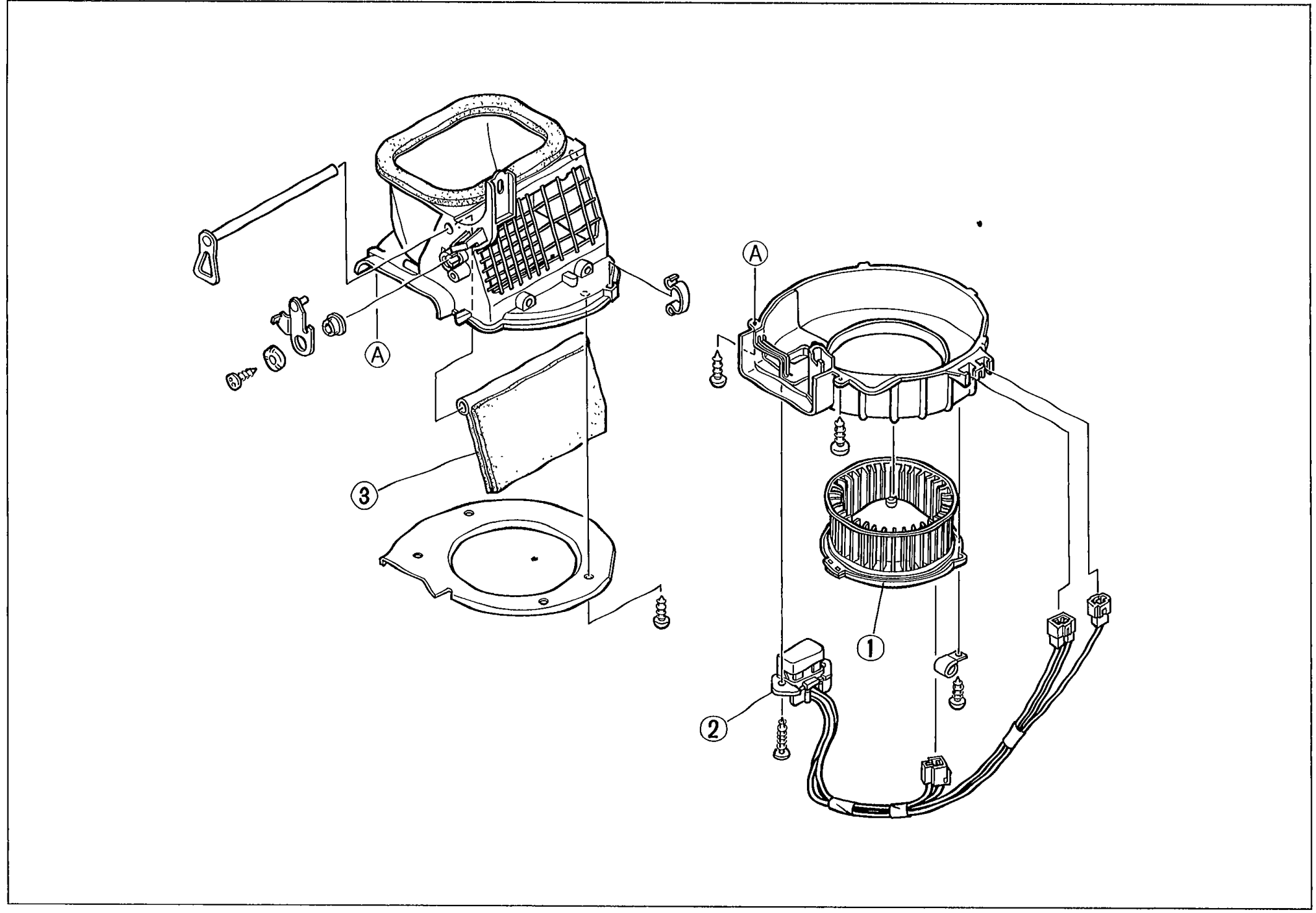
BLOWER UNIT
U-22Exploded view of the blower unit assembly showing the upper housing with the REC-FRESH (recirculate/fresh) air-intake door (3) on the left, the cylindrical blower motor housing (1) on the right with the squirrel-cage fan, and the resistor assembly (2) connector at the lower centre. Two callouts labelled (A) mark the REC-FRESH door pivot pins.
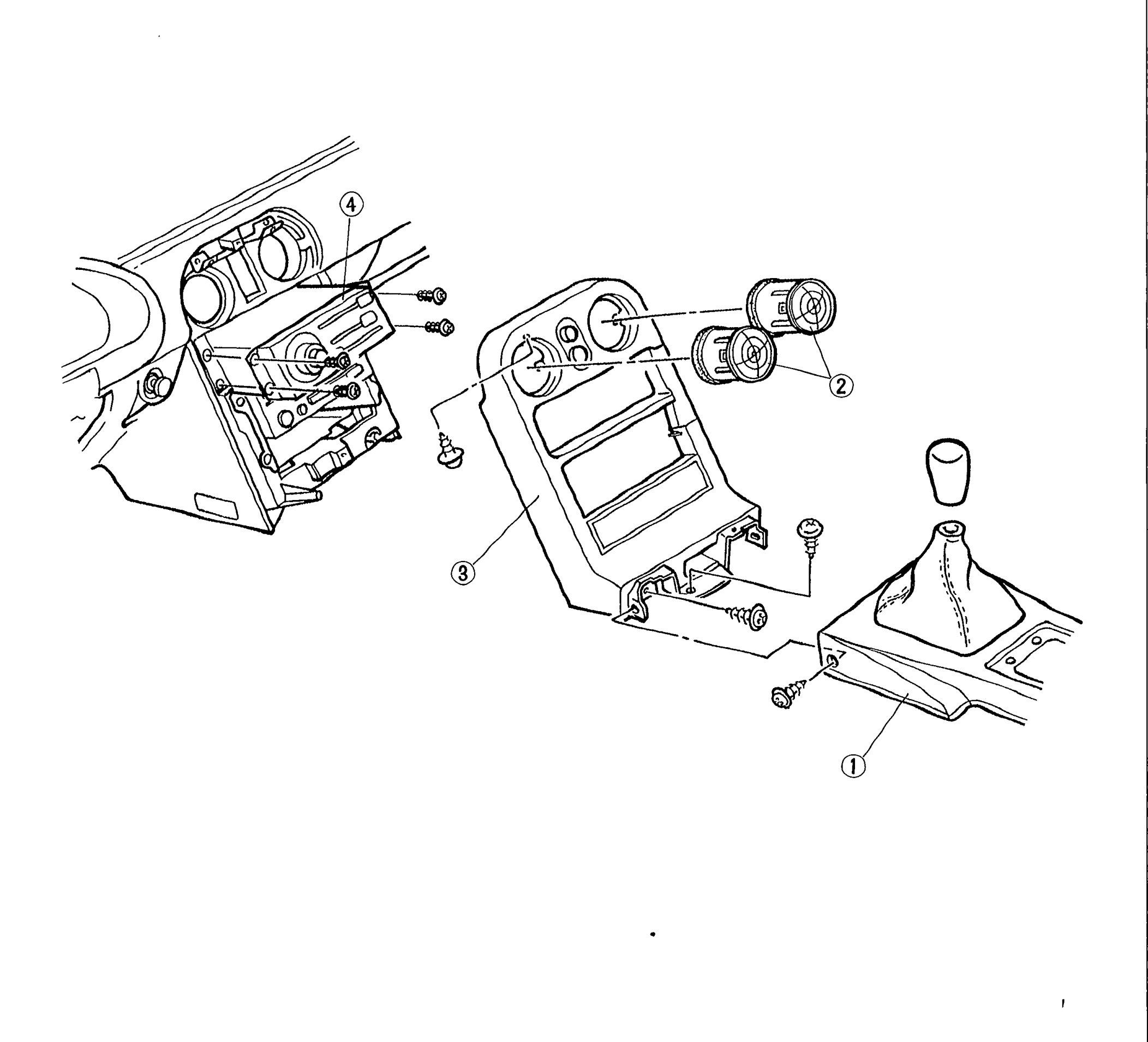
HEATER CONTROL SWITCH ASSEMBLY
U-23Exploded view of the heater control switch assembly area on the centre console. Shows the instrument-cluster surround with the radio aperture on the upper left (callout 4: Rec-Fresh wire), the heater control vent outlet circular knobs with attaching screws (callout 2: Vent outlet), the centre console switch panel (callout 3: Switch panel) below, and the gear-shift boot section of the centre console (callout 1: Center console) on the right.
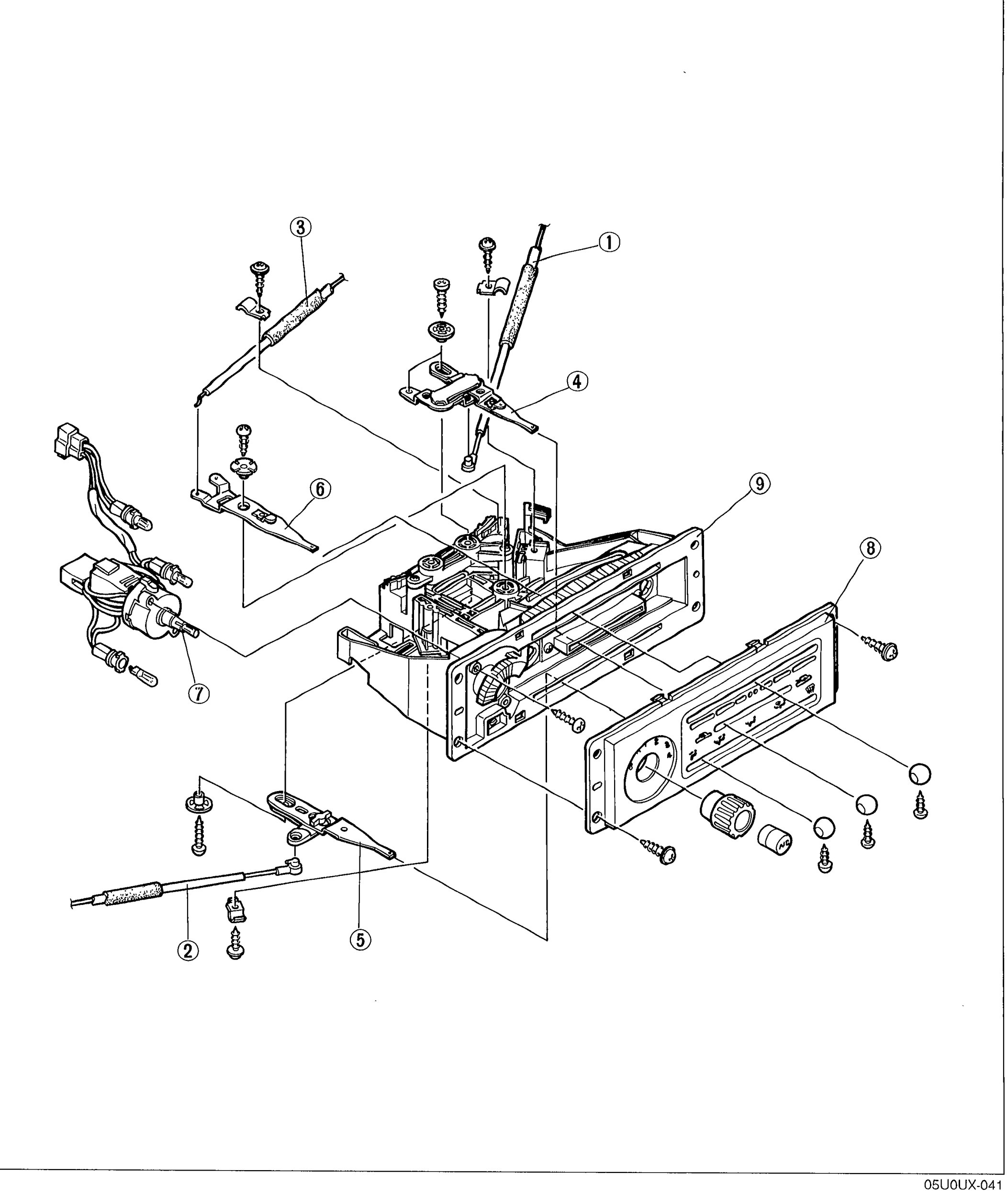
HEATER CONTROL SWITCH ASSEMBLY
U-24Exploded view of the heater control switch assembly. The switch body (9) is in the centre with the rotary control panel (8) on the right (containing the blower/AC switch (7) and the temperature/airflow knobs). The control levers and Bowden cables are exploded around it: Rec-Fresh wire (1) and lever (top), airflow mode wire (2) and lever (5), temperature blend wire (3) and lever (6), and Rec-Fresh lever (4). Numbered callouts 1–9 identify each part with attaching hardware visible.
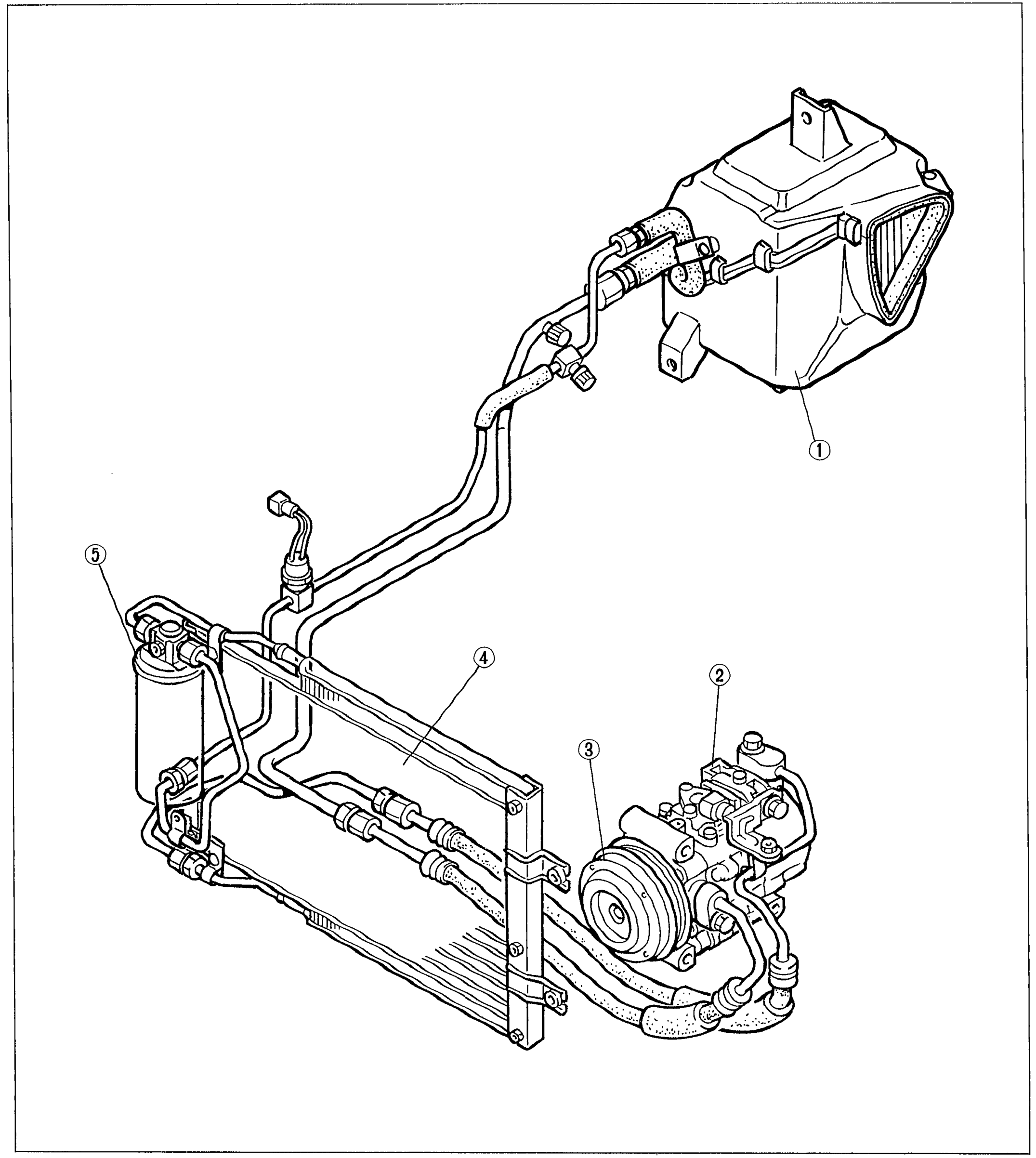
AIR CONDITIONER
U-26Structural view of the air conditioner system showing the major components and their refrigerant plumbing as installed under the hood. The cooling unit / evaporator housing (1) is at the upper right, connected by hoses to the compressor (2) on the right with its magnetic clutch / pulley (3), the condenser (4) horizontal across the front of the vehicle, and the receiver / drier bottle (5) on the left.
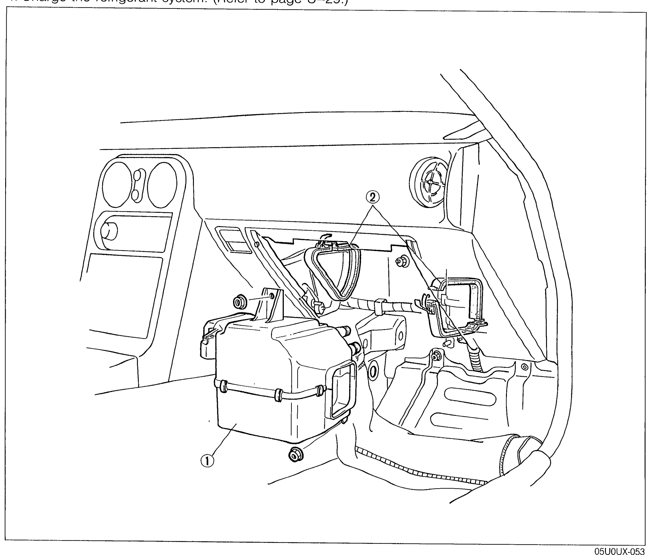
AIR CONDITIONER
U-32Interior view of the right-hand (passenger) side under-dash area showing the cooling unit installed against the firewall, with the heater unit and ducting nearby. Numbered balloon callouts identify: (1) the cooling unit body (lower center), and (2) the sealing plate at the top connection between the cooling unit and the bulkhead. The instrument panel face with vents is visible at the upper-left.
AIR CONDITIONER
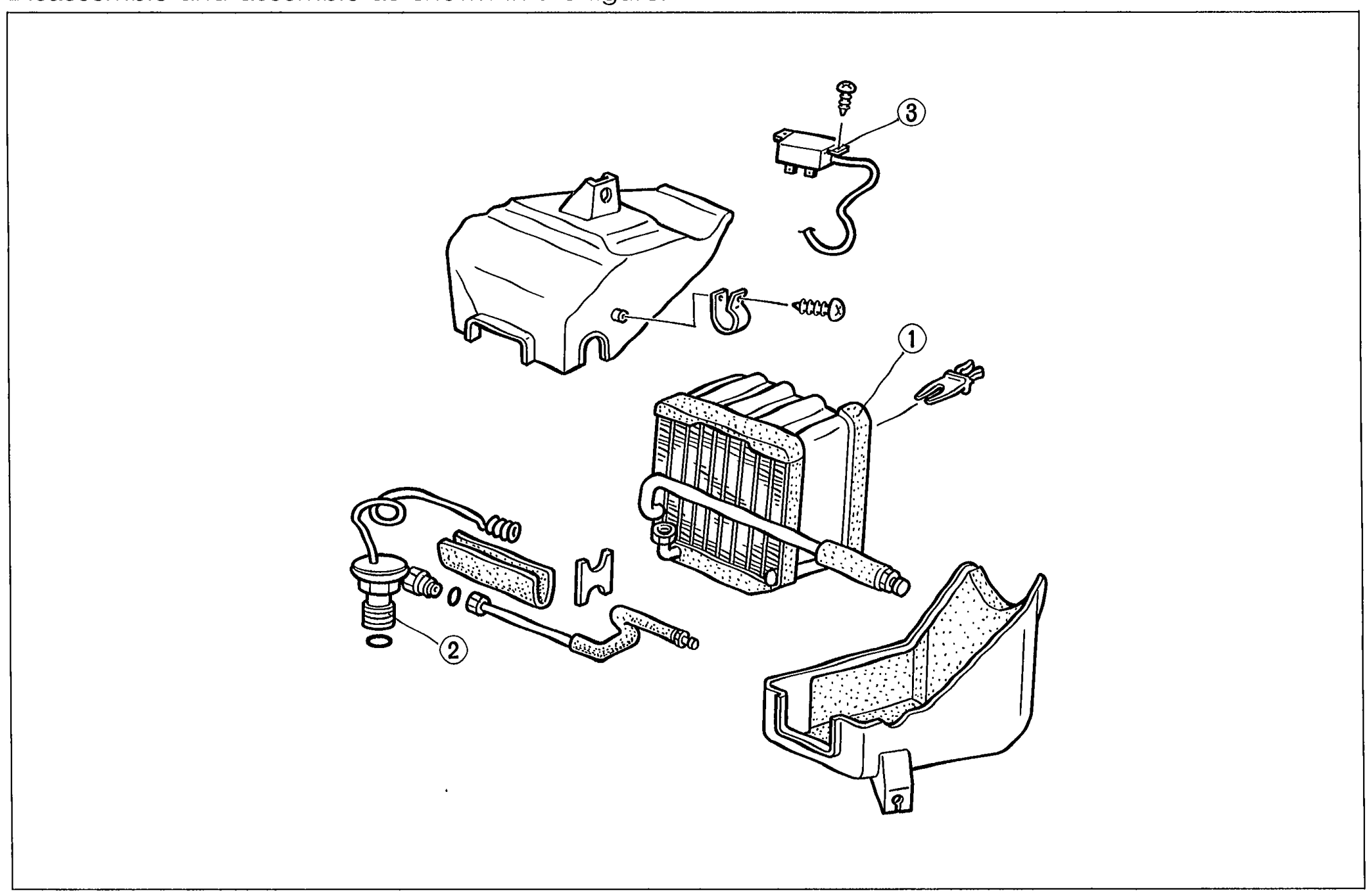
U-33Exploded view of the cooling unit assembly showing the evaporator core in the center, the expansion valve assembly with capillary tube at lower left, the thermoswitch with wire harness at upper right, and the cooling-unit housing/cover. Balloon callouts: (1) Evaporator (center), (2) Expansion valve (lower-left assembly), (3) Thermoswitch (upper-right).
AIR CONDITIONER
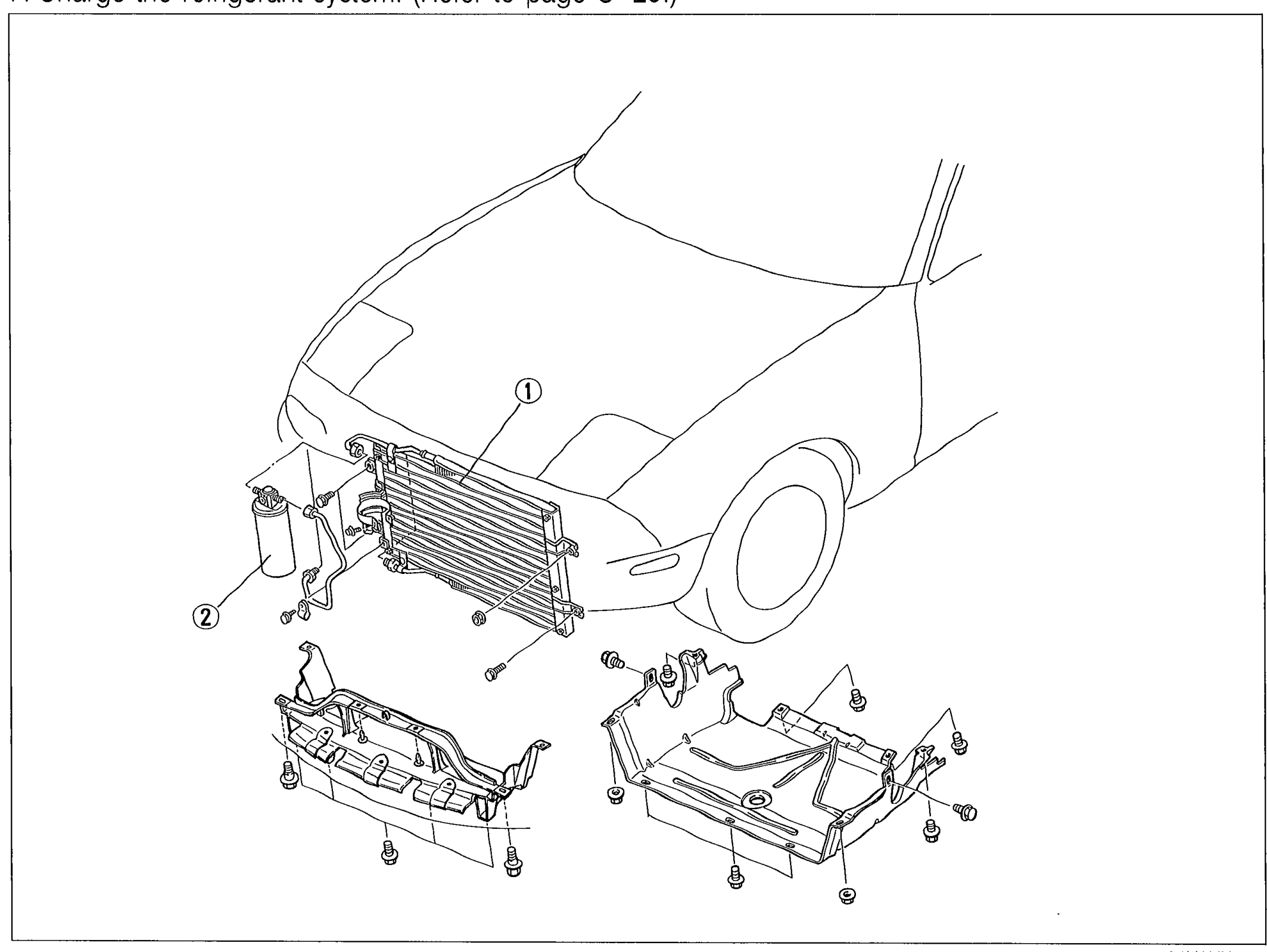
U-35Front three-quarter view of the MX-5 front end with the front bumper/grille area cut away to show the condenser mounted ahead of the radiator and the receiver/drier at the lower-left. Balloon callouts: (1) Condenser (large finned heat exchanger center), (2) Receiver/drier (cylindrical bottle at lower-left). The splash shield and air guide are shown removed below the condenser.
AIR CONDITIONER
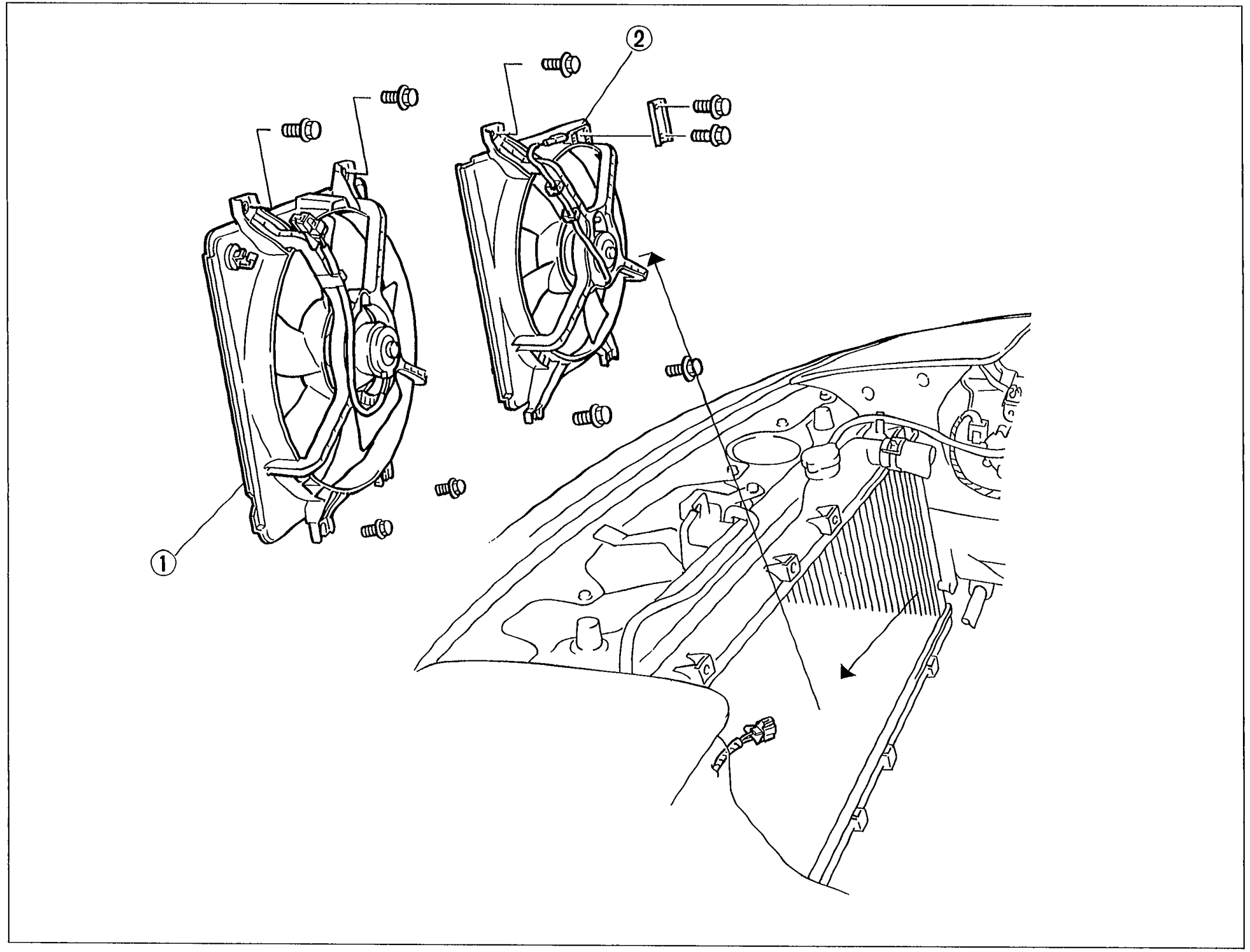
U-38Exploded view of the front-end fan installation. Two fan-shroud assemblies are shown in the upper area with their mounting bolts/screws exploded around them; below is the engine bay showing the radiator/condenser stack and front cross-member. Balloon callouts: (1) Cooling fan (left fan assembly), (2) Condenser fan (right fan assembly).
AIR CONDITIONER
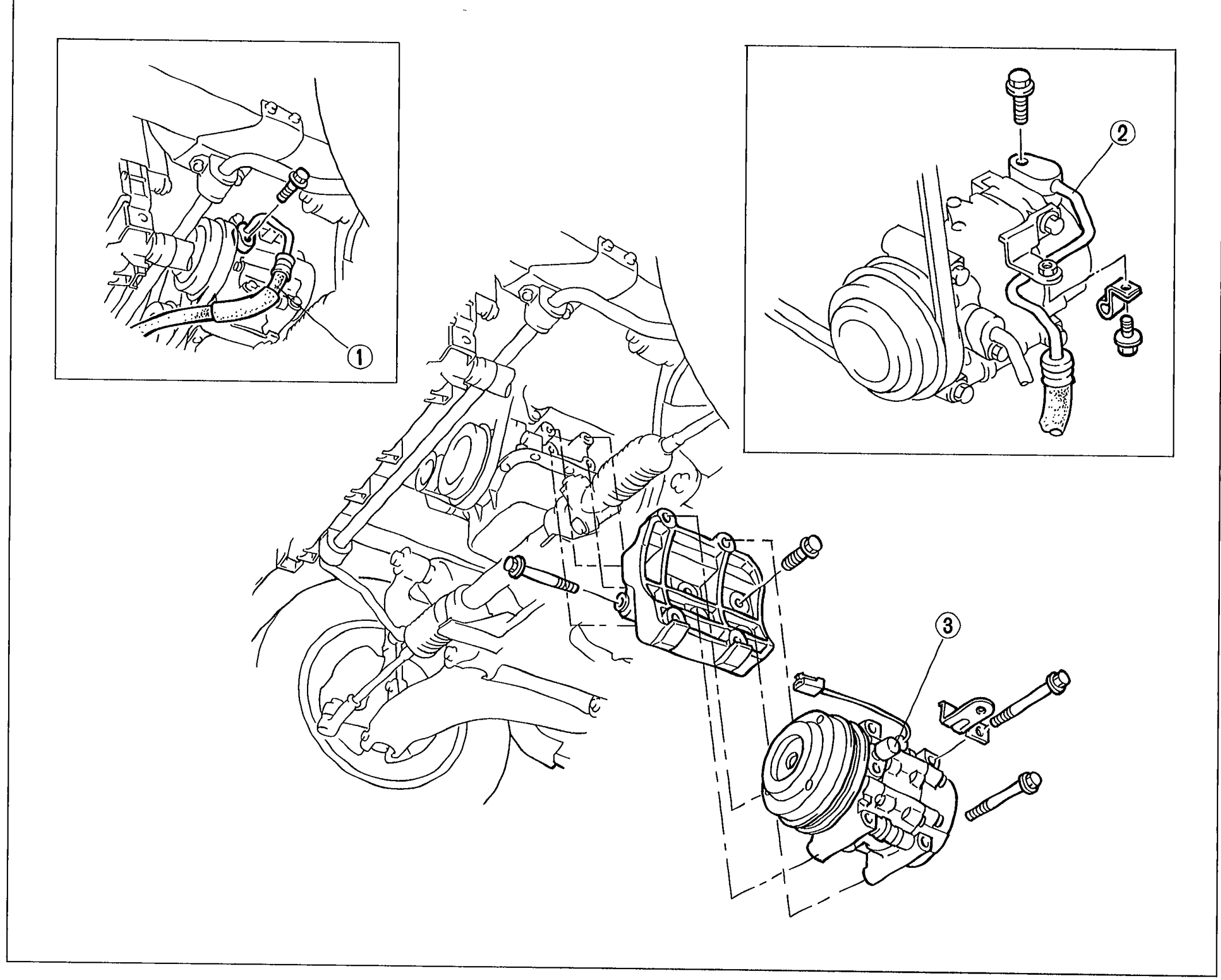
U-40Exploded/installation view of the A/C compressor in the engine bay showing the suction hose (1), discharge hose (2), and compressor (3) with its mounting bolts. Two zoomed-in detail bubbles show the hose fittings and compressor mounting bracket area.
Parts Index
PI178 diagrams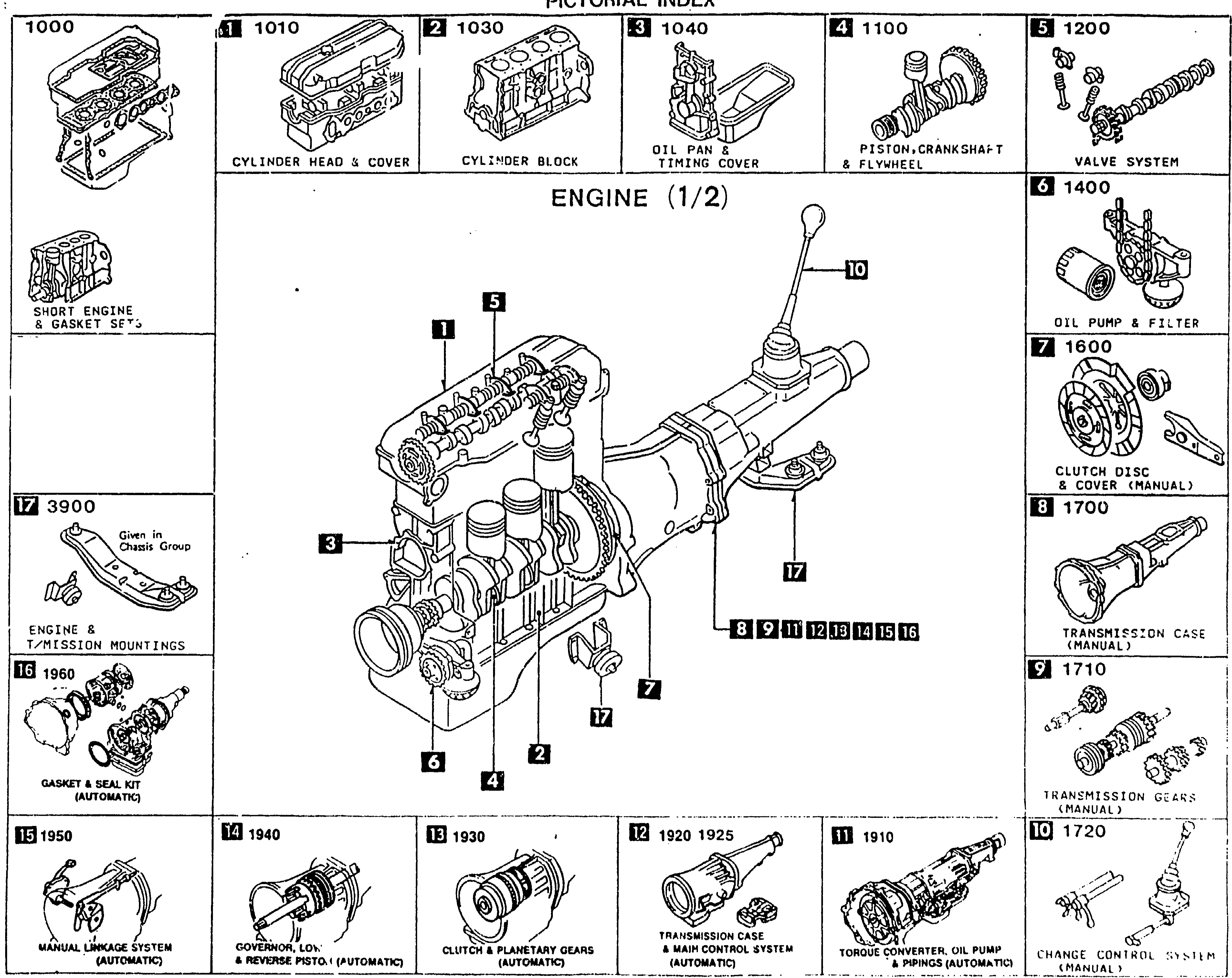
PICTORIAL INDEX — ENGINE (1/2)
1-C 1Pictorial index for the ENGINE (1/2) group of the MX-5 Parts Catalog. Central illustration shows a long-block engine with transmission attached. Surrounding it is a grid of thumbnail drawings, each labeled with a section number (e.g. 1010, 1030, 1040, 1100, 1200, 1400, 1600, 1700, 1710, 1720, 1910, 1920/1925, 1930, 1940, 1950, 1960, 3900) and a part-group name (Cylinder Head & Cover, Cylinder Block, Oil Pan & Timing Cover, Piston/Crankshaft & Flywheel, Valve System, Oil Pump & Filter, Clutch Disc & Cover (manual), Transmission Case (manual), Transmission Gear (manual), Change Control System (manual), Torque Converter / Oil Pump & Piping (automatic), Transmission Case & Main Control System (automatic), Clutch & Planetary Gears (automatic), Governor, Cdl. & Kickdown Piston (automatic), Manual Linkage System, Gasket & Seal Kit (automatic), Short Engine & Gasket Set's, Engine & Mission Mountings). Balloons on the central engine call out where each sub-group appears on the assembly.
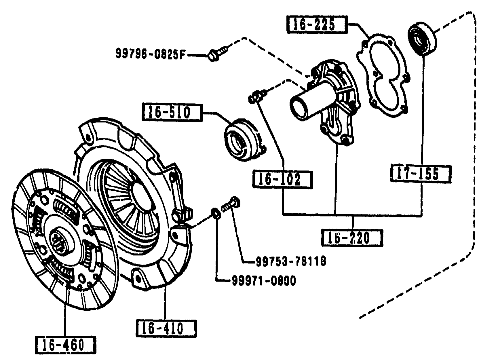
1600 CLUTCH DISC & COVER (MANUAL)
1-C 6Upper exploded view: clutch disc and cover assembly (1600). Shows clutch pivot pin, release bearing collar, clutch fork dust cover, front cover, gasket, fork support, clutch cover with diaphragm spring, and clutch disc. Balloon callouts: 16-225, 99796-0825F, 16-510, 16-102, 17-155, 16-220, 99753-78110, 99971-0800, 16-460, 16-410, 16-232A, 16-410.
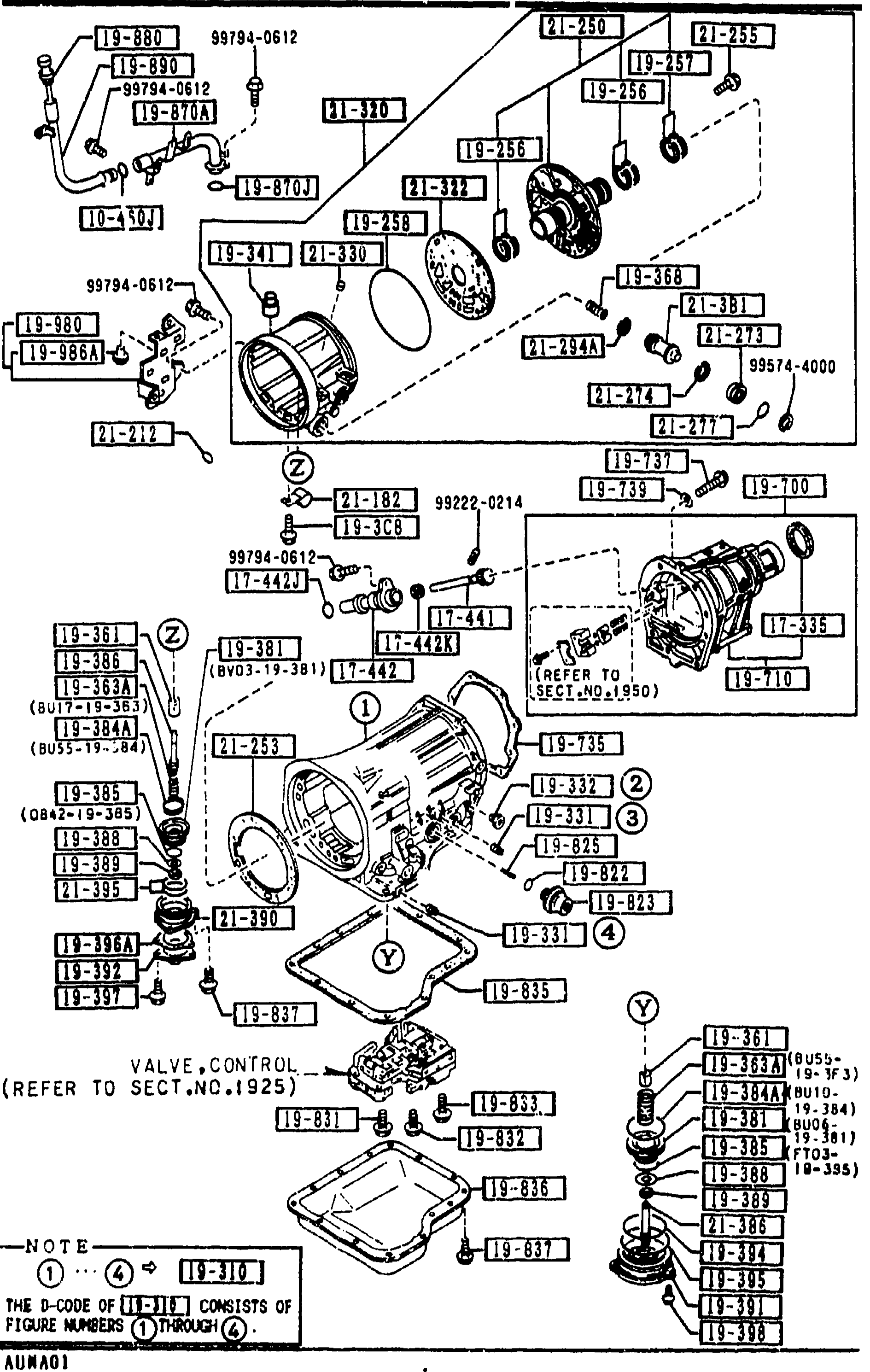
1920 TRANSMISSION CASE & MAIN CONTROL SYSTEM (AUTOMATIC)
1-C 8Final continuation page of the 1920 Transmission Case & Main Control System exploded view. Balloons cover the bracket, accumulator components, drum support, gaskets, plug-accumulator, O-rings, ring seal, piston-accumulator, over-drive case, gasket and one-way valve (balloons 1-13). The 'VALVE,CONTROL (REFER TO SECT.NO.1925)' callout and central NOTE balloon are repeated.
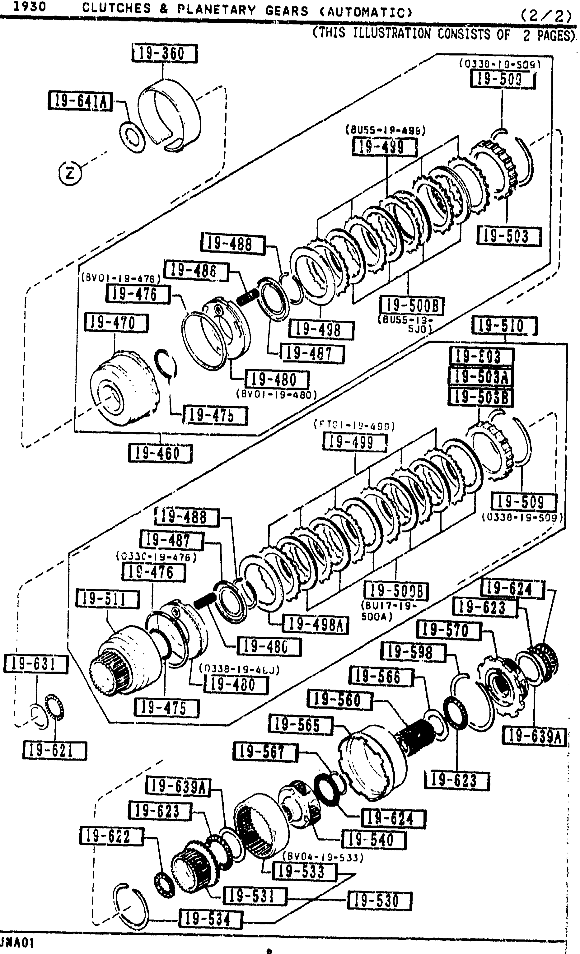
1930 -6 M CLUTCHES & PLANETARY GEARS (AUTOMATIC) (CONT'D)
1-C 9Exploded view (sheet 2 of 2) of clutches and planetary gears for the automatic transmission. Shows multiple sub-assemblies stacked vertically with balloon callouts referencing part numbers in the 19-xxx series (e.g. 19-360, 19-487, 19-488, 19-498, 19-500B, 19-503, 19-503A, 19-509, 19-510, 19-540, 19-565, 19-587, 19-623, 19-624, 19-639A). Marked '(THIS ILLUSTRATION CONSISTS OF 2 PAGES)'. Bottom-left figure-ref label 'AUNA01'.
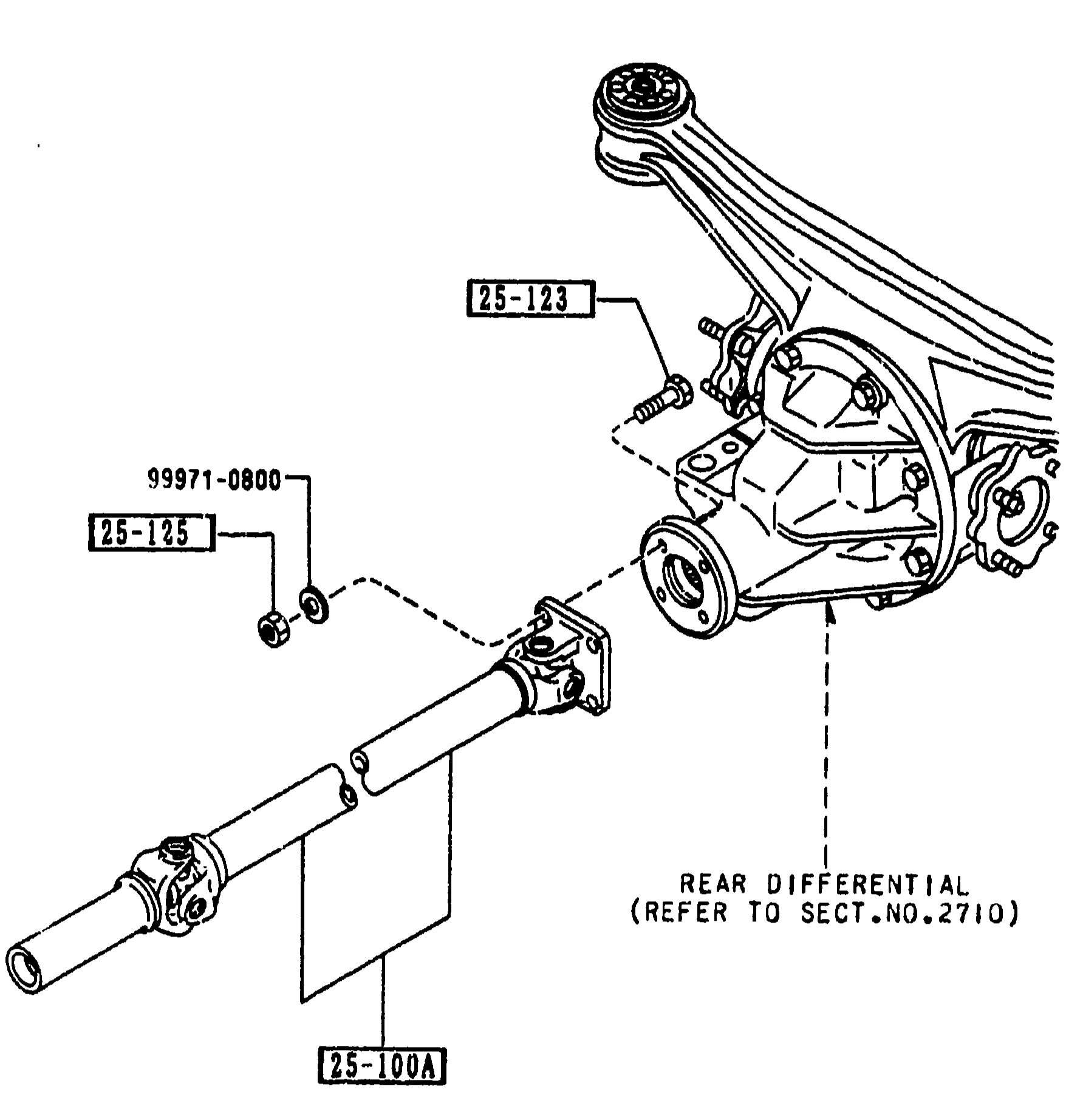
2505 REAR PROPELLER SHAFT
1-C11Exploded view of the rear propeller shaft assembly mating to the rear differential. The propeller shaft runs from lower-left up to the differential pinion flange on the right. Balloon callouts: 25-100A (SHAFT, PROPELLER) on the shaft body, 25-123 (BOLT) at the pinion-flange bolts, 99971-0800 and 25-125 (NUT) at the left end. A leader points to 'REAR DIFFERENTIAL (REFER TO SECT.NO.2710)'.
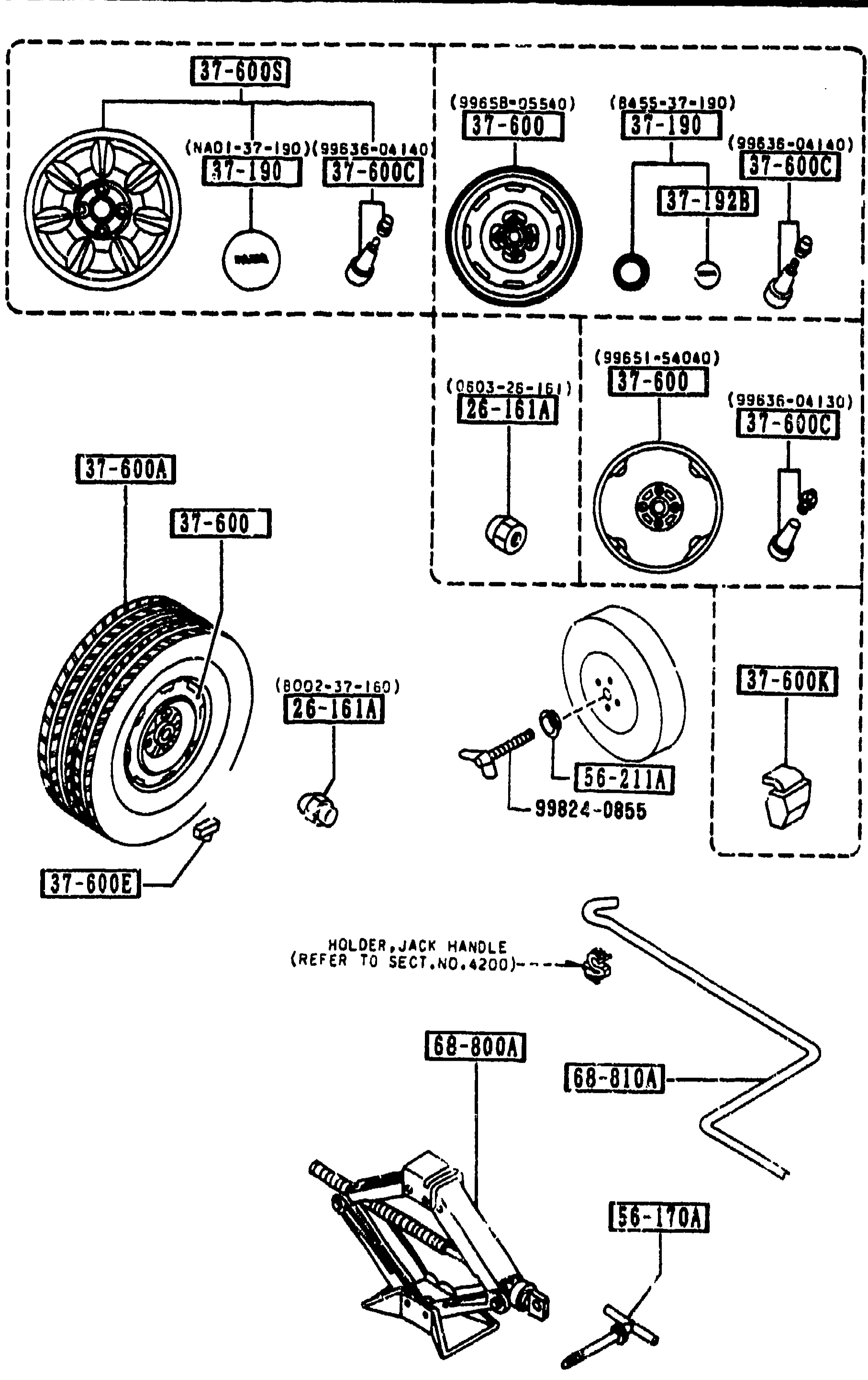
3700 TIRES & JACK
1-C14Exploded view of tire & jack assembly for section 3700. Top group shows two alloy/disc wheels (37-190, 37-600S, 37-600C, 37-192B) with hub nuts (NA01-37-190, 99858-04140, 26-161A, 0603-26-161) and emblem/center caps. Middle group shows a tire (37-600A, 37-600) with bolt/clamp (26-161A, 0002-37-160) and second wheel (37-600, NA01-37-190, 99838-04130). Bottom-left shows valve and weight items (56-211A, 99824-0855, 37-600E, 37-600K). Bottom shows a scissor jack assembly (68-800A, 68-810A, 56-170A) with HOLDER, JACK HANDLE note referring to SECT.NO.4200.
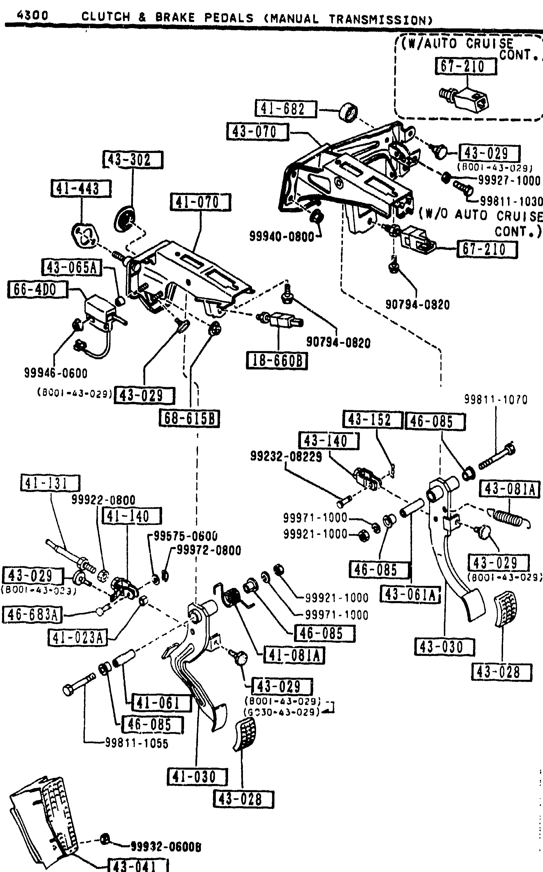
4300 CLUTCH & BRAKE PEDALS (MANUAL TRANSMISSION)
1-C16Final continuation of clutch and brake pedal assemblies (manual transmission, page 4300-3). Same exploded view as previous pages — only base brake-light switch (B001-66-490A) without auto cruise option and flange cap nut (68-615B) listed in this section's table.
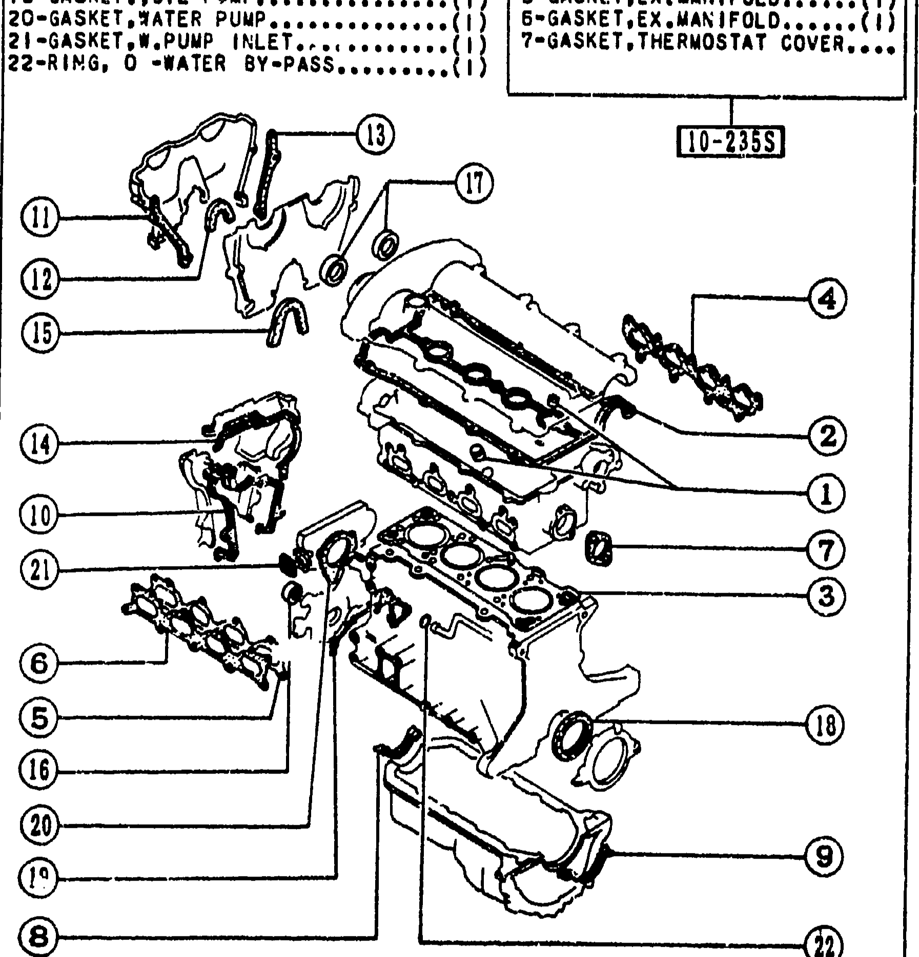
1000 — SHORT ENGINE & GASKET SETS
1-C3Bottom-left large exploded view labeled '10-2[?]55' showing the cylinder-head + block sub-assembly with balloon callouts 1-22 keyed to the smaller legend at the top right of the figure (1-SEAL,VALVE; 2-GASKET,HEAD COVER; 3-GASKET,CYLINDER HEAD; 4-GASKET,IN.MANIFOLD; 5-GASKET,EX.MANIFOLD; 6-GASKET,OIL PAN; 7-GASKET,OIL PUMP; 8-GASKET,THERMOSTAT COVER). Each balloon is paired with a Mazda part-number tag.
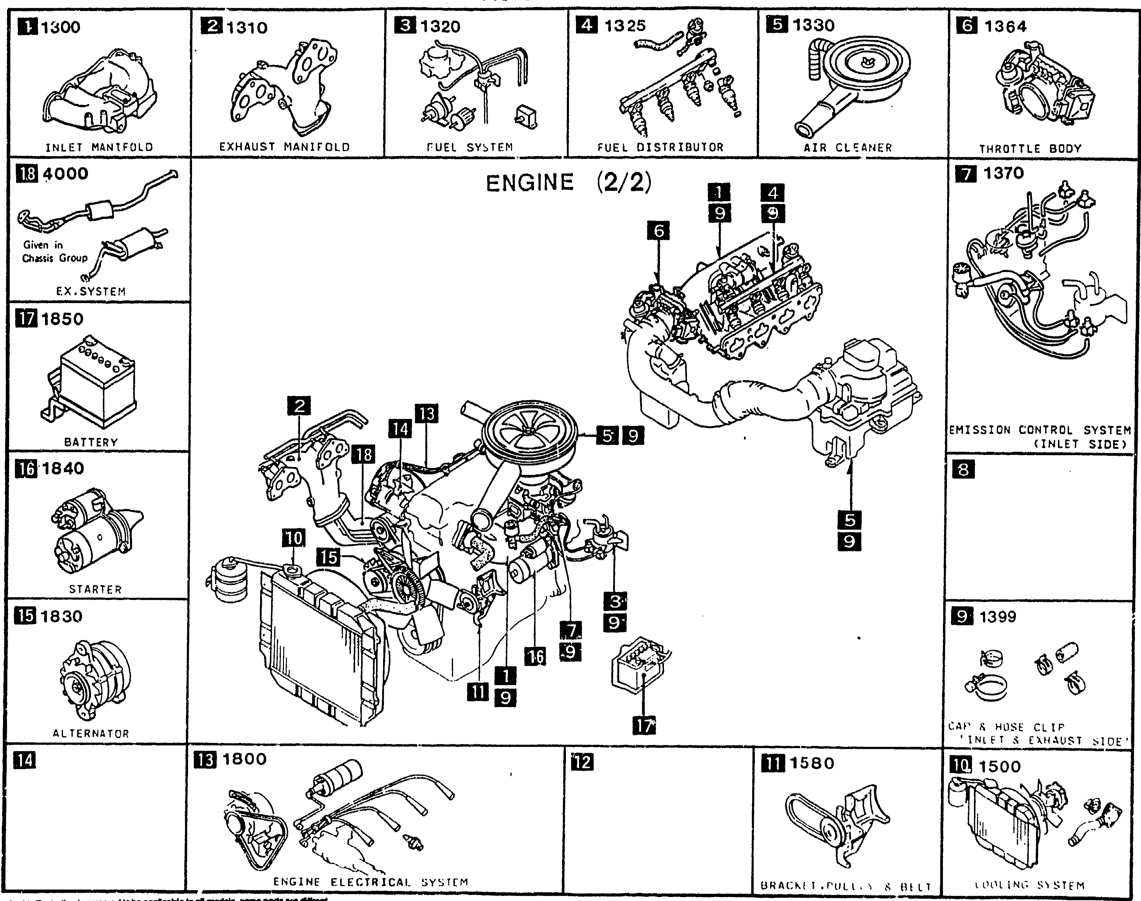
PICTORIAL INDEX — ENGINE (2/2)
1-D 1Pictorial index continuation for the ENGINE (2/2) group of the MX-5 Parts Catalog. Central illustration: front-three-quarter view of the engine with intake/exhaust manifolds, accessory drive, and radiator. Surrounding thumbnails labeled with section numbers and group names: 1300 Inlet manifold, 1310 Exhaust manifold, 1320 Fuel system, 1325 Fuel distributor, 1330 Air cleaner, 1364 Throttle body, 1370 Emission control system (inlet side), 1399 Cap & hose clip 'inlet & exhaust system', 1500 Cooling system, 1580 Bracket, pulley & V belt, 1800 Engine electrical system, 1830 Alternator, 1840 Starter, 1850 Battery, 4000 Ex. system (also given in chassis group). Balloons on the central engine illustration cross-reference each thumbnail to its location on the assembly.
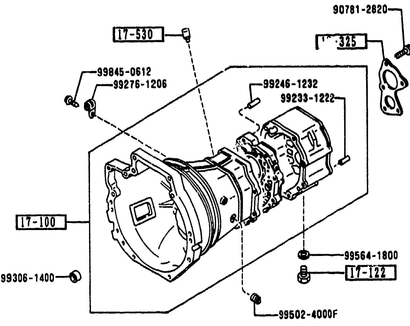
1700 TRANSMISSION CASE (MANUAL)
1-D 6Upper exploded view of the manual transmission case (1700): main transmission housing with extension housing and cover plates. Callouts include 17-530 (breather), 17-325 (cover, bearing), 99246-1232, 99233-1222, 99275-1206, 99845-0612, 17-100 (case T/mission), 17-122 (plug, magnet), 99306-1400, 99564-1800, 17-330 (housing, extension), 17-335 (seal, oil), 99502-4000F.
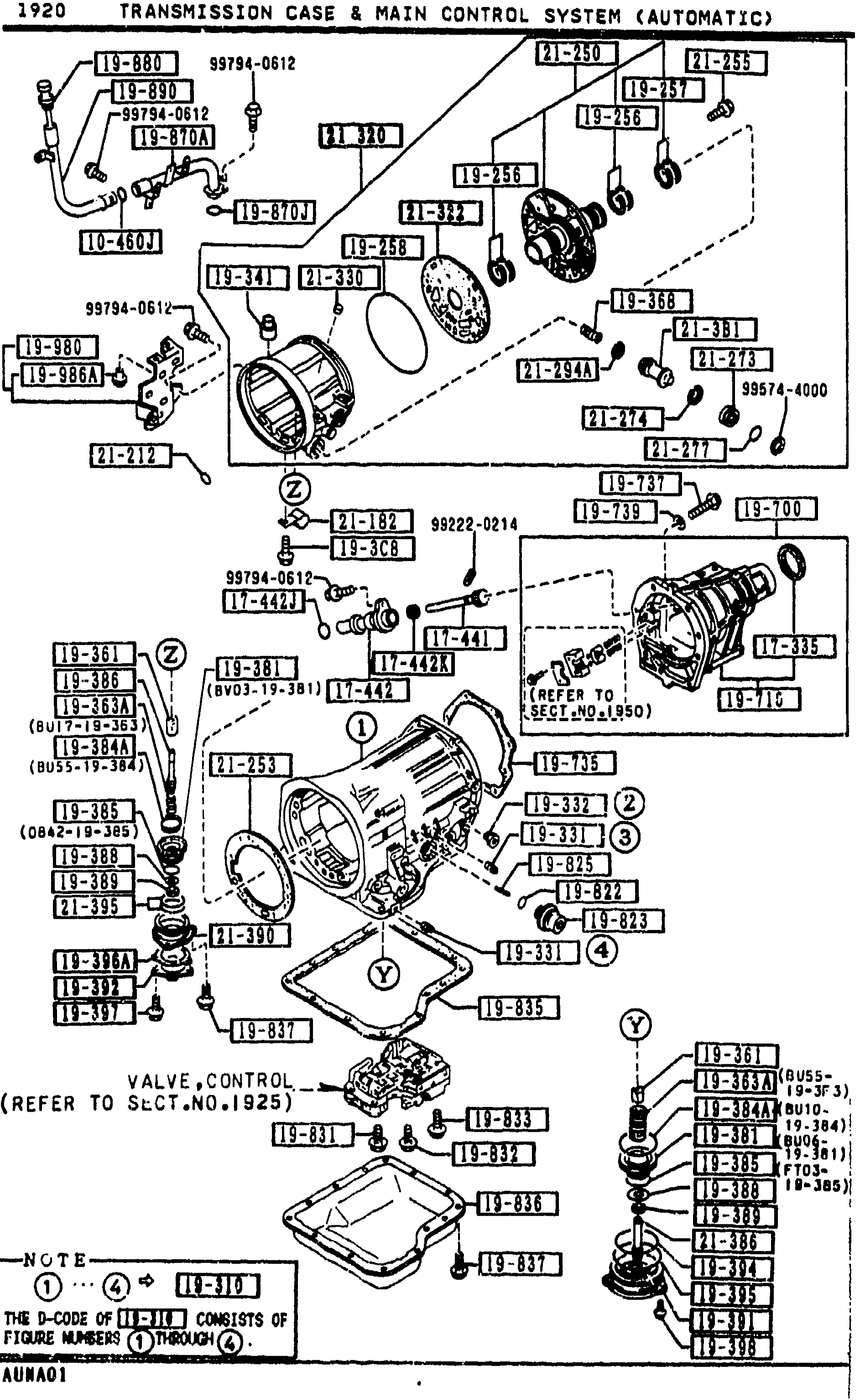
1920 TRANSMISSION CASE & MAIN CONTROL SYSTEM (AUTOMATIC)
1-D 8Exploded view of the automatic transmission case and main control assembly. Shows the transmission case housing (center) with attached oil pan (lower), valve body / control valve assembly at bottom-left labeled 'VALVE,CONTROL (REFER TO SECT.NO.1925)', servo cover assembly upper-right with piston band parts, governor / output shaft at right, and many fasteners and seals identified by balloon callouts (e.g. 18-880, 18-870, 19-261, 18-260, 18-256, 18-259, 18-258, 18-810, 18-870A, 18-339, 18-340, 18-345, 18-368, 18-156, 18-265, 21-180, 18-3CB, 18-381, 18-441, 18-442A, 18-444, 18-335, 18-265, 18-441, 18-380A, 18-331, 18-339, 18-332, 18-330, 18-355, 18-836, 18-3061, 18-3064A, 18-364, 18-832, 18-837, 18-355). NOTE at lower-left: D-CODE of figure numbers 1 through 4 (figures 18-3061 / 18-359) consists of figure numbers 1 through 4.
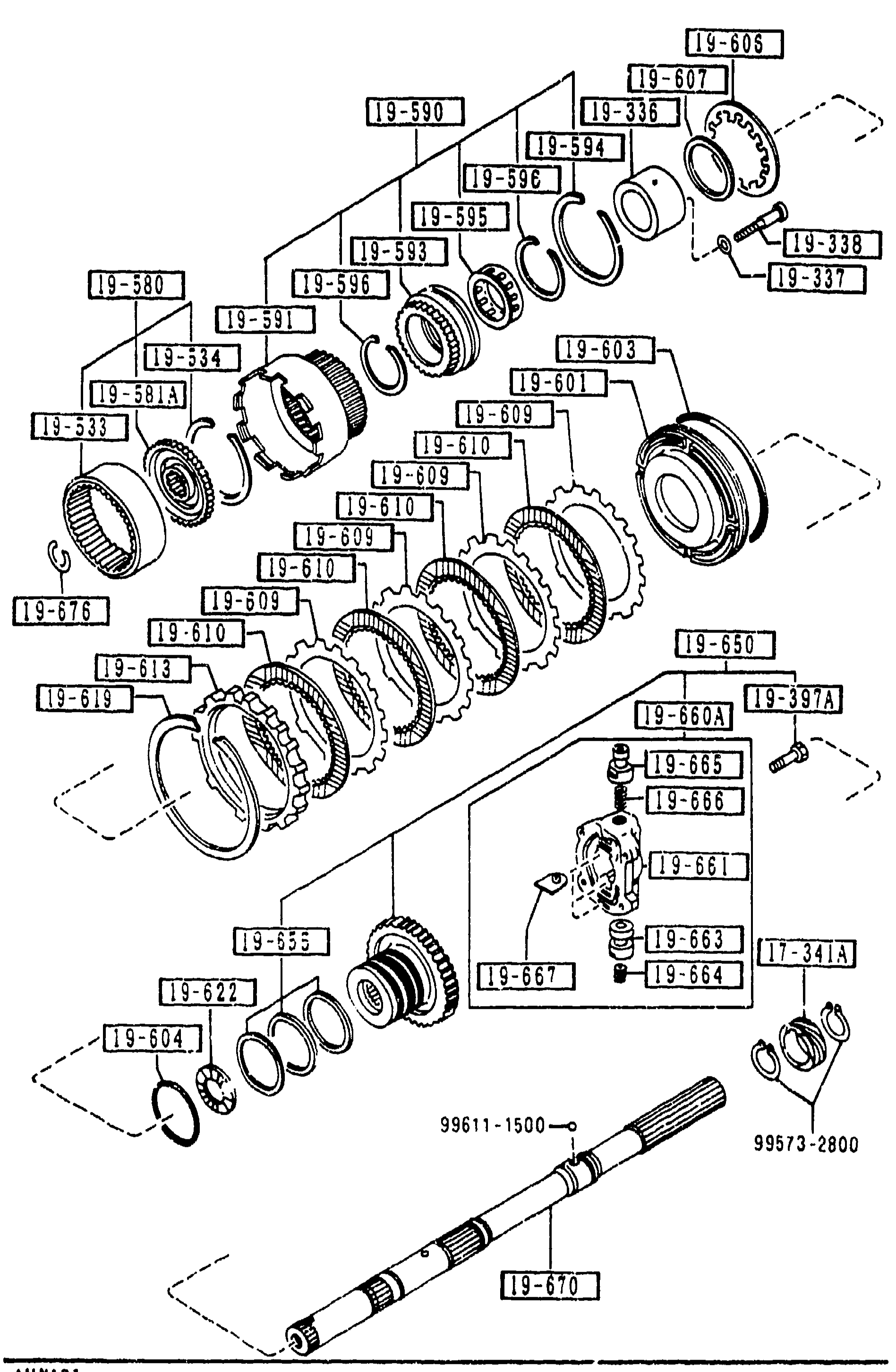
1940 GOVERNOR, LOW & REVERSE PISTON (AUTOMATIC)
1-D 9Exploded view of the governor, low & reverse piston (automatic transmission) assembly. Shows planetary gear set, drum/clutch components and an output shaft with reference dimensions (99611-1500 and 99573-2800). Balloon callouts in the 19-xxx range plus 17-341A. Figure-ref label 'AUNA01' at bottom-left.
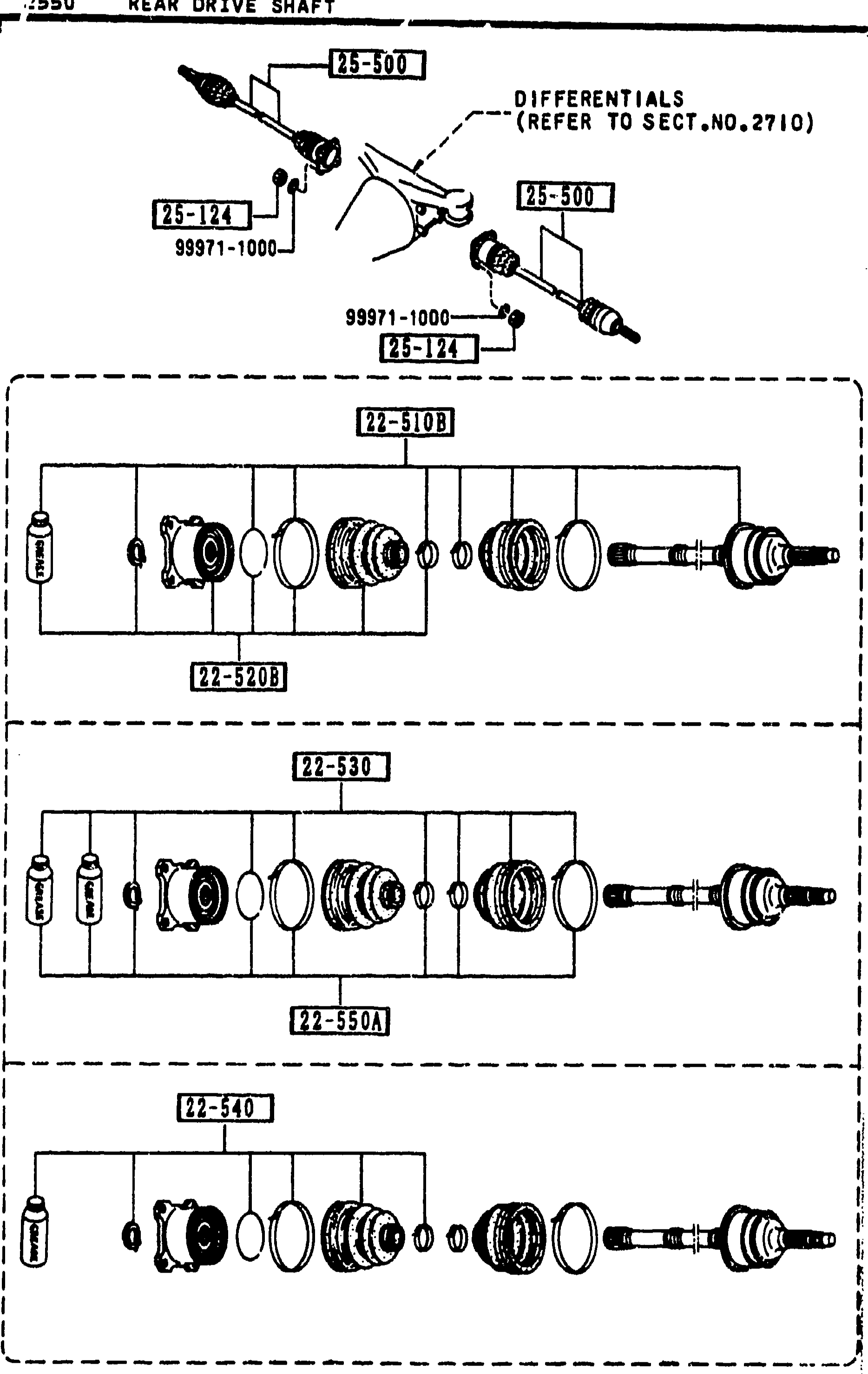
2550 REAR DRIVE SHAFT
1-D11Composite exploded view of the rear drive shaft (left half of page). Top: overall vehicle-level diagram showing two drive shafts mating to the rear differential (25-500 shafts, 25-124 nuts, 99971-1000 washers, labelled 'DIFFERENTIALS (REFER TO SECT.NO.2710)'). Below are three sub-exploded views of the drive-shaft components: 22-510B (joint set, outer) with 22-520B detail; 22-530 (boot set, outer joint) with 22-550A (clip set, drive shaft); and 22-540 (boot set, inner joint).
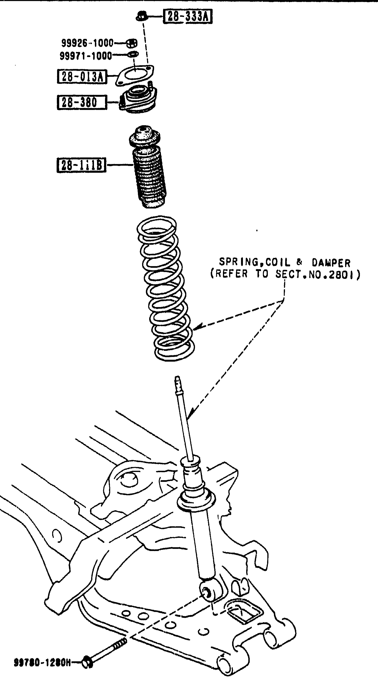
REAR SUSPENSION MECHANISMS
1-D12Exploded view of the rear suspension mechanisms showing the upper damper mount stack atop the lower control arm and knuckle bracket. Components from top: nut/flange (28-333A), washer (99926-1000), nut (99971-1000), sheet rubber (28-013A), mounting rubber (28-380), bump stopper (28-111B), coil spring & damper assembly (label 'SPRING,COIL & DAMPER REFER TO SECT.NO.2801'), and lower mounting bolt (98780-1280H).
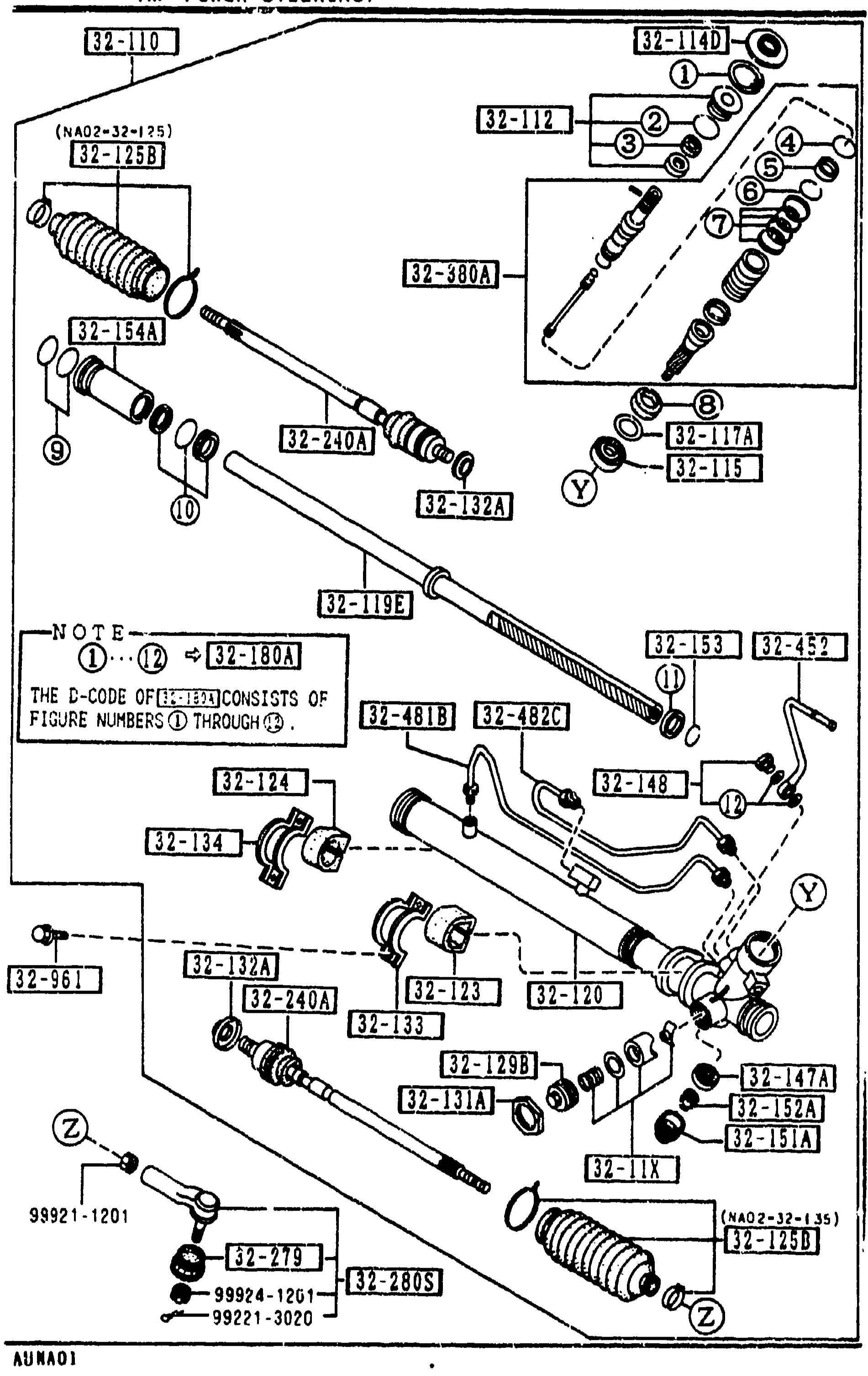
3220 A STEERING GEAR (W/ POWER STEERING)
1-D13Exploded view of the power-steering rack-and-pinion gear assembly. Shows the steering rack housing (center, long horizontal), pinion shaft with bearings (upper right), tie-rod ends, inner ball joints, dust boots (32-280A/32-280B), pinion-shim variants, valve gear, clamps, and many balloon callouts (32-110, 32-114N, 32-126, NA01-32-125, 32-125B, 32-280A, 32-380A, 32-154A, 32-240A, 32-132A, 32-115, 32-117A, 32-115A, 32-192B, 32-153, 32-180A, 32-452, 32-481B, 32-124, 32-134, 32-145, 32-148, 32-152A, 32-153, 32-159, 32-960B, 32-461, 32-280B, 32-240A, 32-152A, 32-131A, 32-152A, 32-151A, 32-961, 99921-1201, 99924-1201, 99921-3020). NOTE at lower-left: 'THE D-CODE OF [32-3061] CONSISTS OF FIGURE NUMBERS (1) THROUGH (5)' with callout circles (1) through (5) shown on figure.
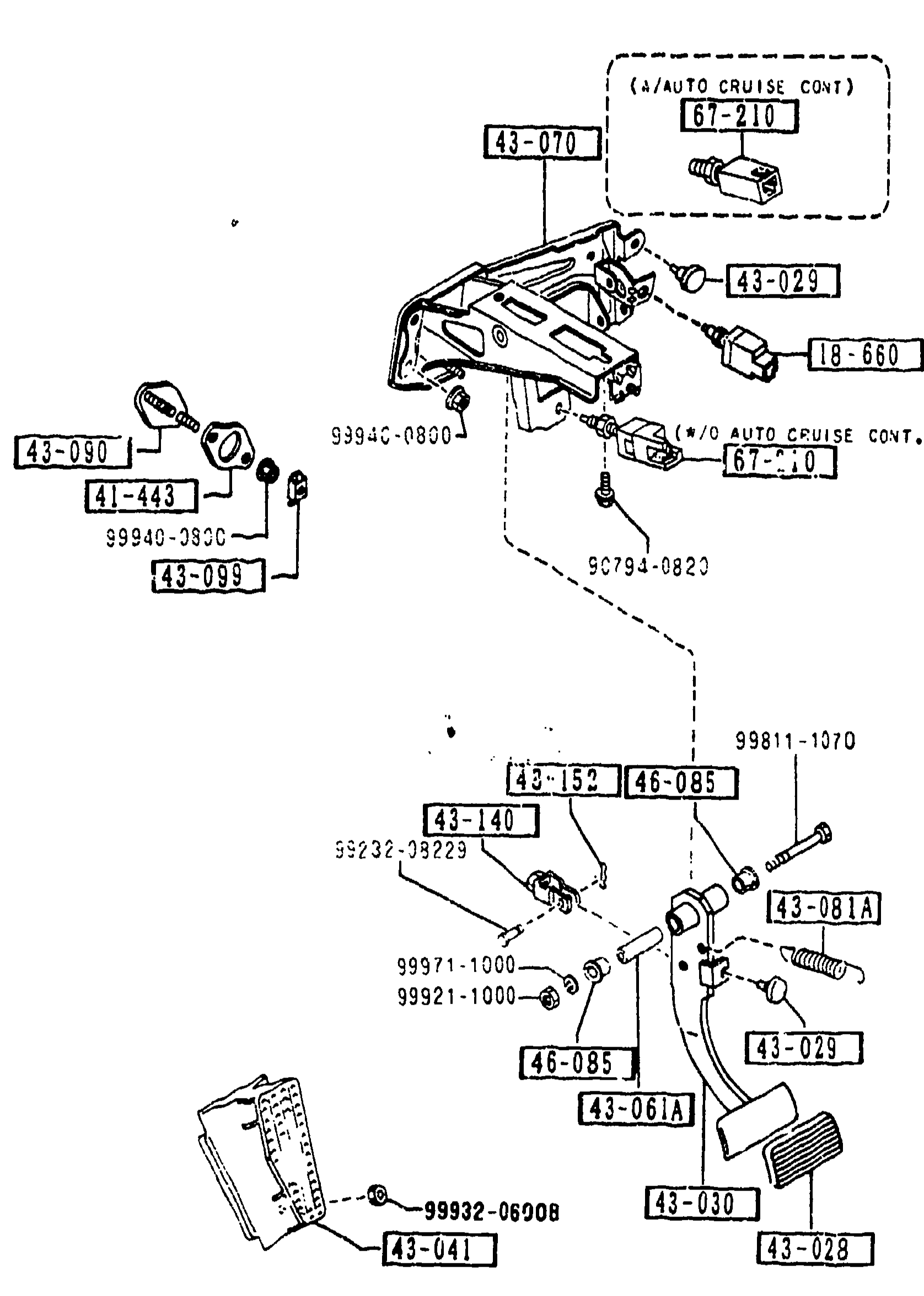
4300A BRAKE PEDALS (AUTOMATIC TRANSMISSION)
1-D16Exploded view of the brake pedal assembly for automatic-transmission cars (section 4300A). Master cylinder bracket (43-070), brake pedal (43-030) with stopper rubber (43-029) and pad (43-028), kick-down switch (1M-860), brake-light switch (67-210), gasket (41-443), foot rest (43-041), pipe pedal (43-061A), return spring (43-081A), plate (43-090) with holder (43-099), brake fork (43-140), snap pin (43-152). Variants for w/ and w/o auto cruise control.
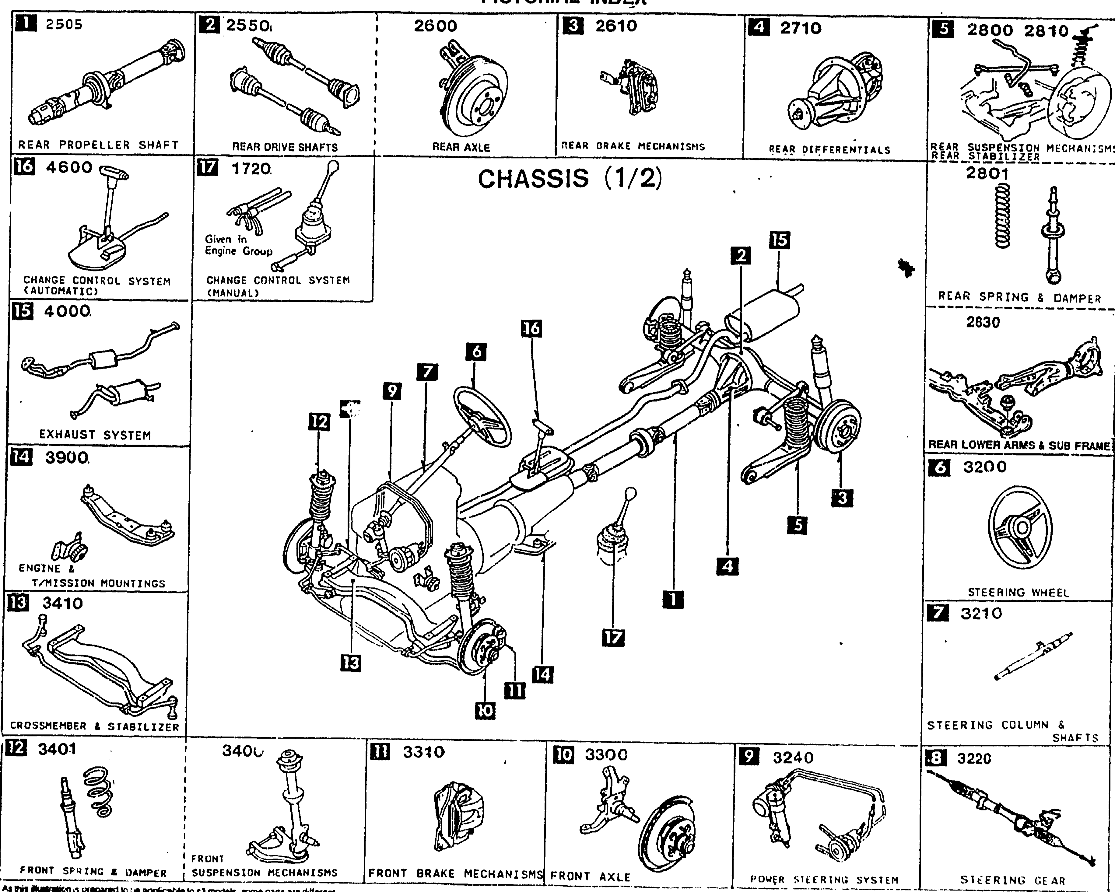
PICTORIAL INDEX — CHASSIS (1/2)
1-E 1Pictorial index for the CHASSIS (1/2) group of the MX-5 Parts Catalog. Central illustration: top-down rolling-chassis view (no body) showing rear differential, propeller shaft, suspension, front subframe, steering column and gear. Surrounding thumbnails labeled with section numbers and group names: 2505 Rear propeller shaft, 2550 Rear drive shafts, 2600 Rear axle, 2610 Rear brake mechanism, 2710 Rear differentials, 2800/2810 Rear suspension mechanism, 2801 Rear springs & damper, 2830 Rear lower arms & sub frame, 3200 Steering wheel, 3210 Steering column & shafts, 3220 Steering gear, 3240 Power steering system, 3300 Front axle, 3310 Front brake mechanism, 3401 Front spring & damper, 3402 Front suspension mechanism (note: label reads '340?'), 3410 Crossmember & stabilizer, 3900 Engine & mission mountings, 4000 Exhaust system, 1720 Change control system (manual; given in engine group), 4600 Change control system (automatic). Balloons on the central illustration cross-reference each thumbnail to its position on the chassis.
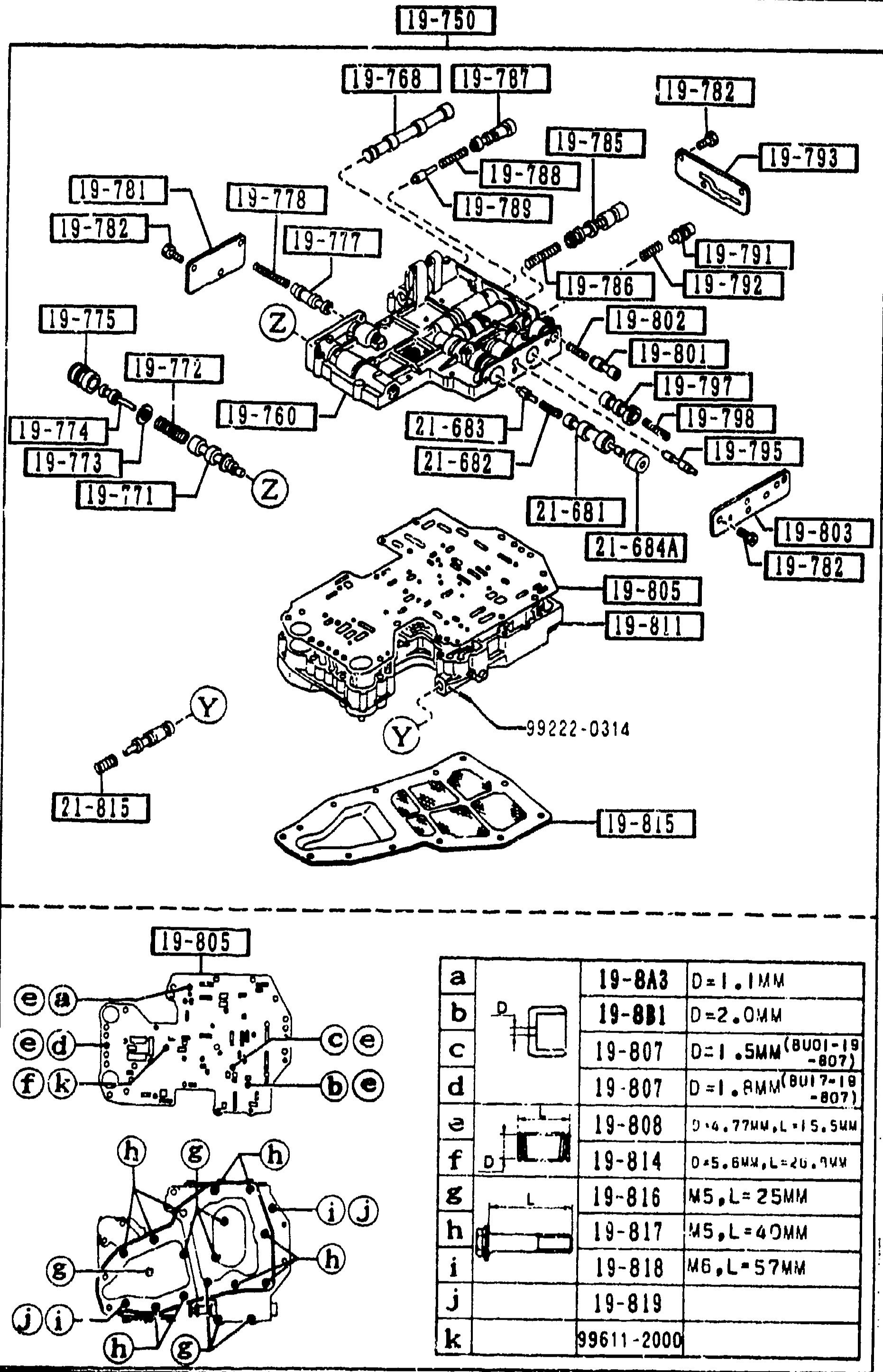
1925 CONTROL VALVE (AUTOMATIC)
1-E 8Exploded view of the automatic transmission control valve (valve body) assembly. Upper portion shows the main valve body with multiple stacked plates, springs, and individual spool valves identified by balloon callouts (19-7A1, 19-760, 19-760A, 19-768, 19-769, 19-771, 19-772, 19-773, 19-7C1, 19-774, 19-775, 19-776, 19-777, 19-778, 19-779, 19-815, 19-816, 19-825, 19-826, 19-840, 19-220, 19-225). A separator-plate diagram with bolt-position legend (lower-left, items a-k) maps to a bolt-size sub-table: a=19-8A1 D-1.1MW, b=19-801 D-2.0MW, c=19-803 D-3.5MW, d=19-813 W4L*40MW, e=19-814 W4L*70MW, f=19-815 W5L*45MW, g=19-817 W5L*40MW, h=19-817 W5L*45MW, i=19-818 W5L*57MW, j=19-819. Bottom-right shows part 99611-2000. Figure reference 99222-0314 visible mid-figure (assembly hardware).
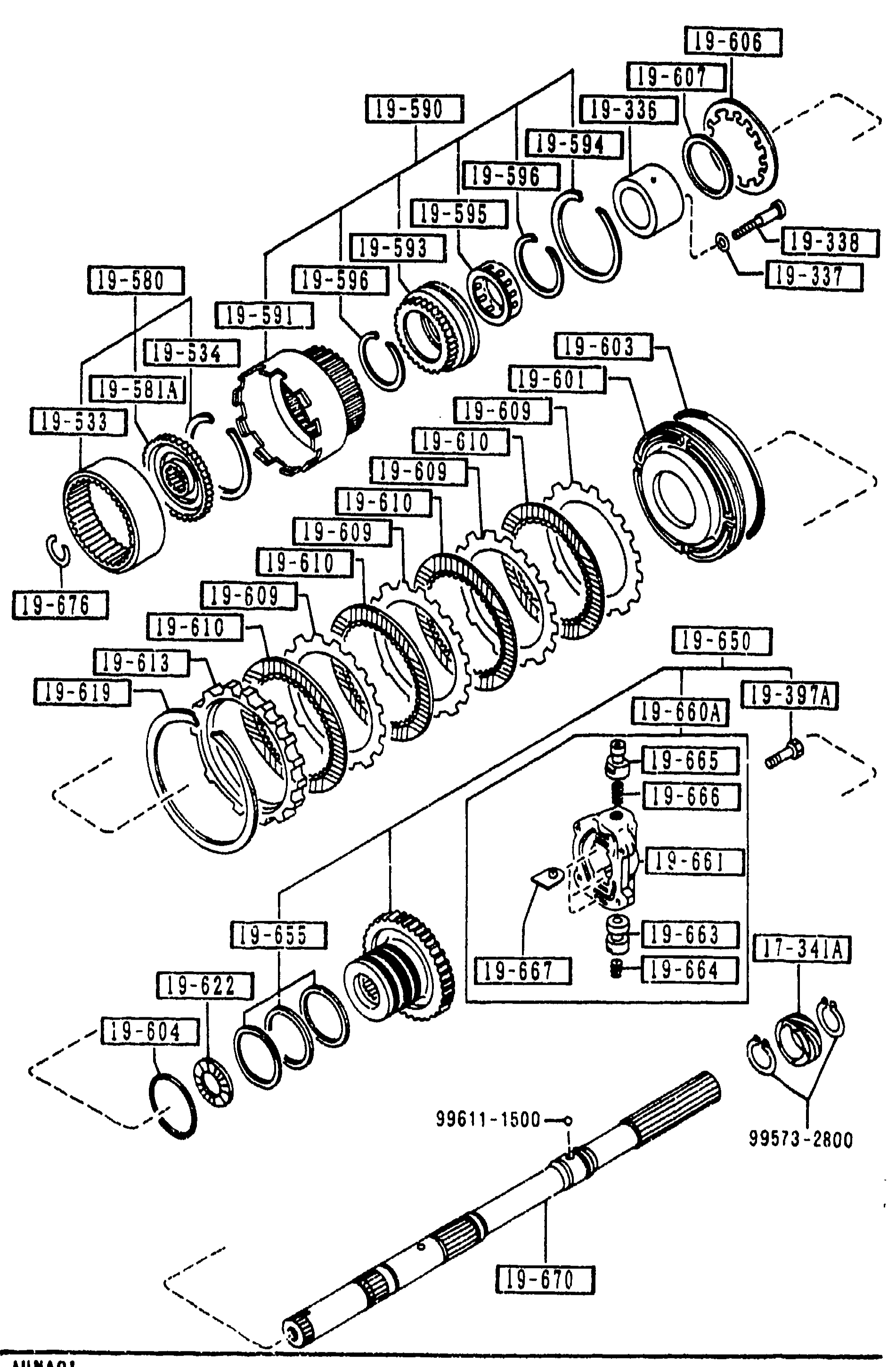
1940 GOVERNOR, LOW & REVERSE PISTON (AUTOMATIC) (CONT'D)
1-E 9Repeat of the governor/low & reverse piston exploded view (same illustration as page 1-D 9) with balloon callouts in the 19-xxx range plus 17-341A. Output shaft at bottom shows reference dimensions 99611-1500 and 99573-2800.
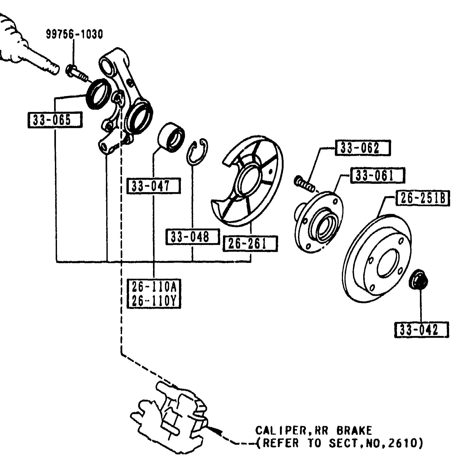
2600 REAR AXLE
1-E11Exploded view of the rear axle/knuckle assembly (left half of page). Shows from left to right: knuckle (26-110A/26-110Y), 99756-1030 stud, 33-065 oil-axle seal, 33-047 wheel bearing, 33-048 retaining ring (disc plate), 26-261 dust cover, 33-061 wheel hub, 33-062 hub bolt, 26-251B disc plate, and 33-042 nut/washer. A leader at bottom points to 'CALIPER, RR BRAKE (REFER TO SECT.NO.2610)'.
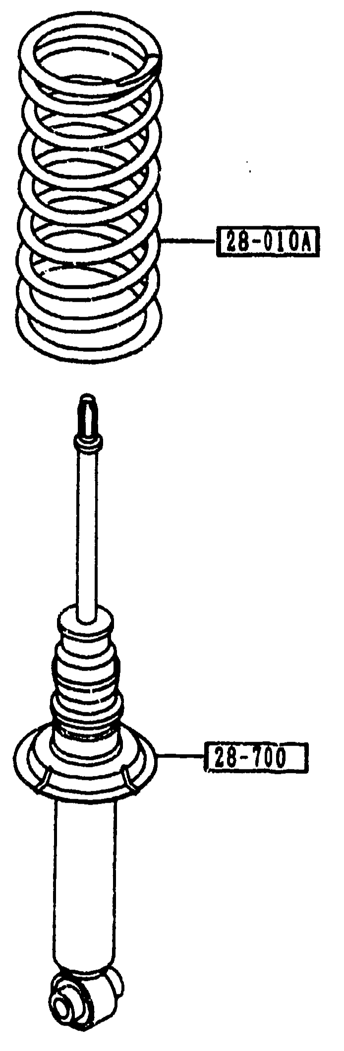
REAR SPRING & DAMPER
1-E12Exploded view showing two components: a rear coil spring (top) labeled 28-010A, and below it the rear damper (28-700) with bump-stopper boot and lower mounting eye bushing.
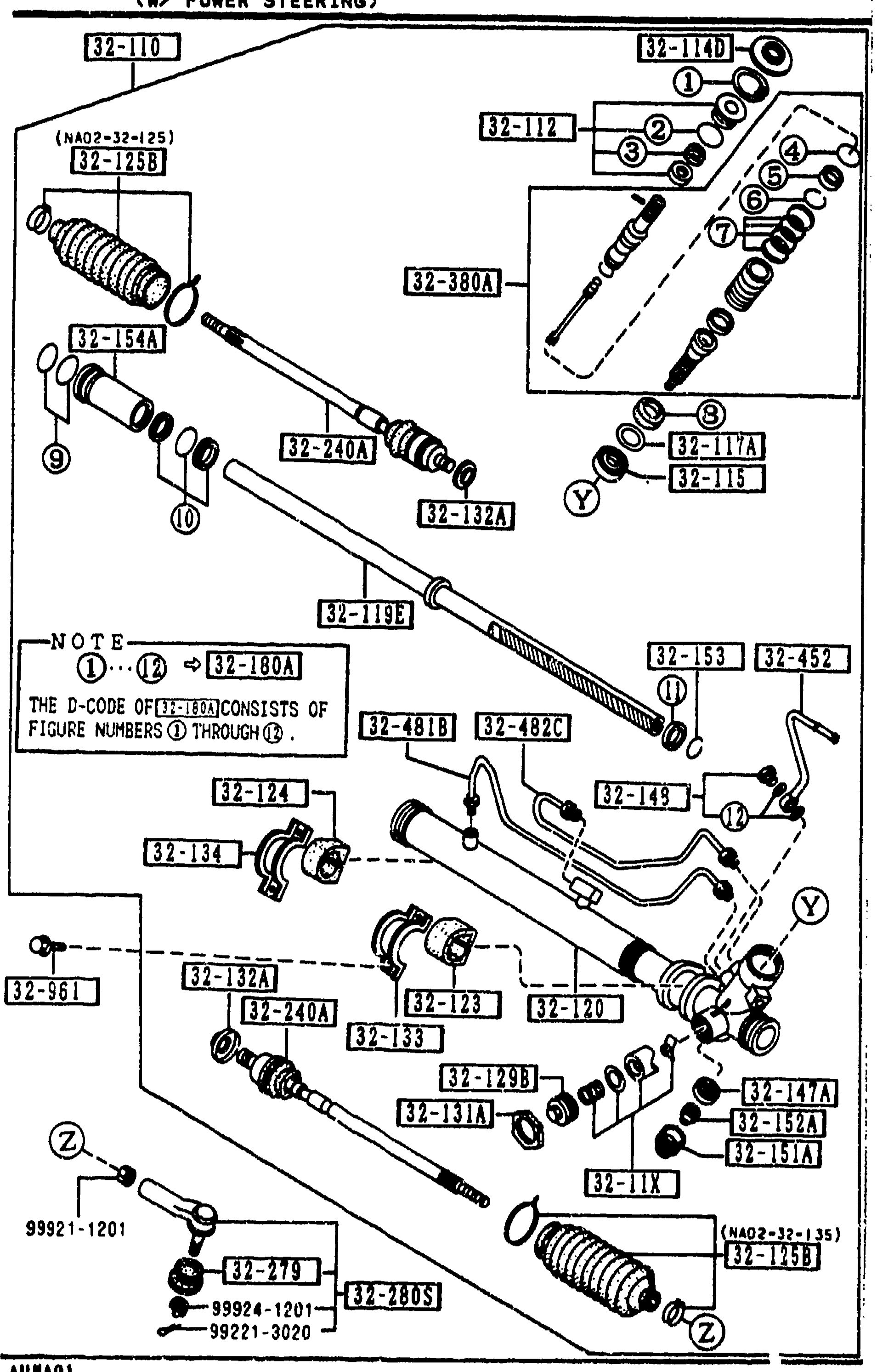
3220 A STEERING GEAR (W/ POWER STEERING)
1-E13Continued exploded view of the power-steering rack-and-pinion gear assembly. Shows the rack housing with cylinder/pinion section detail (upper right) — including hydraulic pipes A and B for the cylinder (32-481B / 32-482C), pipe B' for steering gear (32-452), the rack/pinion with valve, tie-rod ends with dust seals (32-279, 32-280B), and many balloon callouts (32-110, 32-114H, 32-112, 32-125B, NA02-32-125, 32-380A, 32-154A, 32-240A, 32-132A, 32-115, 32-117A, 32-145, 32-119B, 32-153, 32-180A, 32-452, 32-481B, 32-124, 32-134, 32-145, 32-152A, 32-145, 32-1293, 32-120, 32-461, 32-280B, 32-240A, 32-152A, 32-131A, 32-152A, 32-151A, 32-961, 99921-1201, 99924-1201, 99921-3020). NOTE at center-left: 'THE D-CODE OF [32-180A] CONSISTS OF FIGURE NUMBERS (1) THROUGH (9)' with callout circles (1) through (9). Z-loop callout shows tie-rod end ball-joint group.
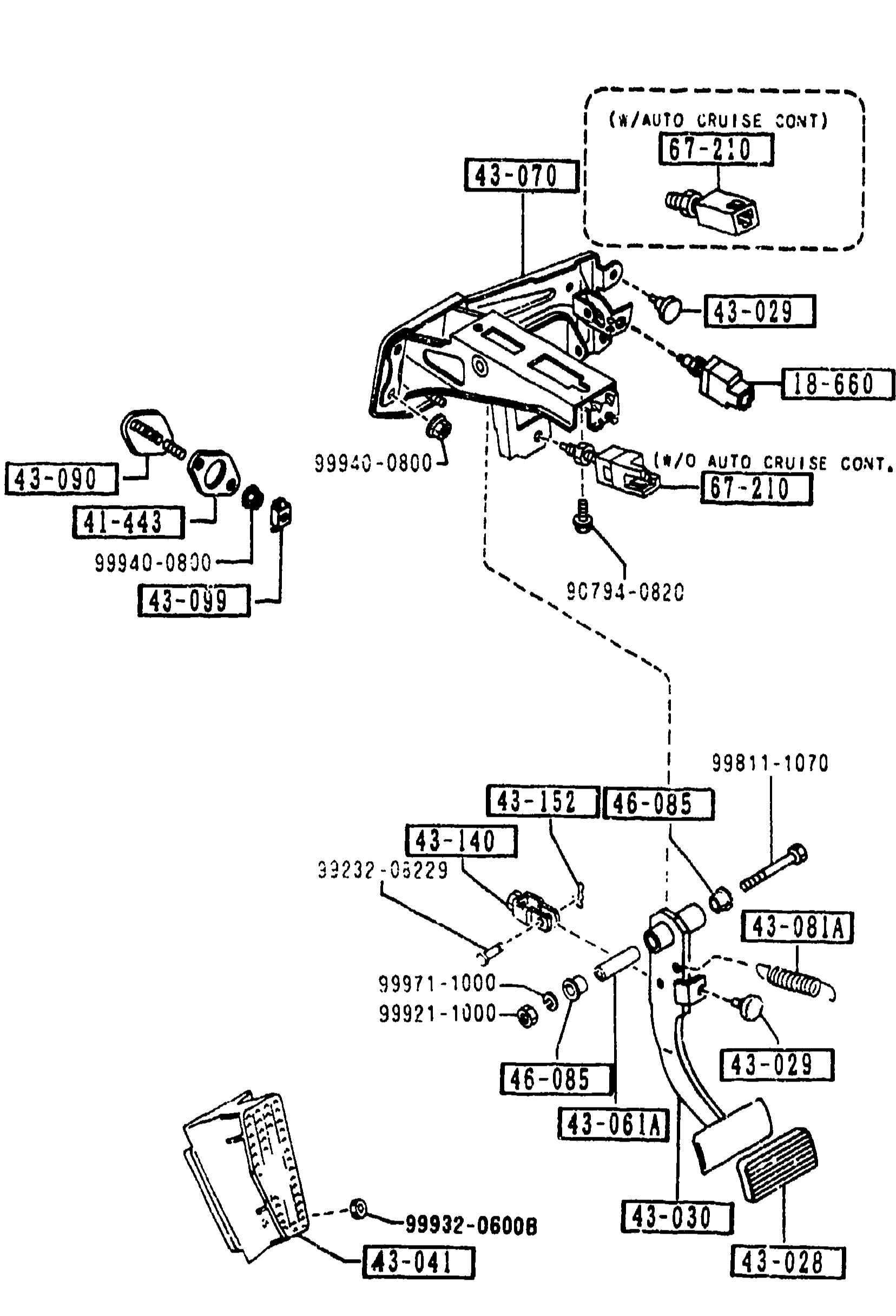
4300A BRAKE PEDALS (AUTOMATIC TRANSMISSION)
1-E16Continued exploded view of the AT brake pedal assembly (page 4300A-2). Same illustration as preceding page covering the snap pin, bush, brake-light switch (with/without auto cruise control) and master cyl. bracket assembly.
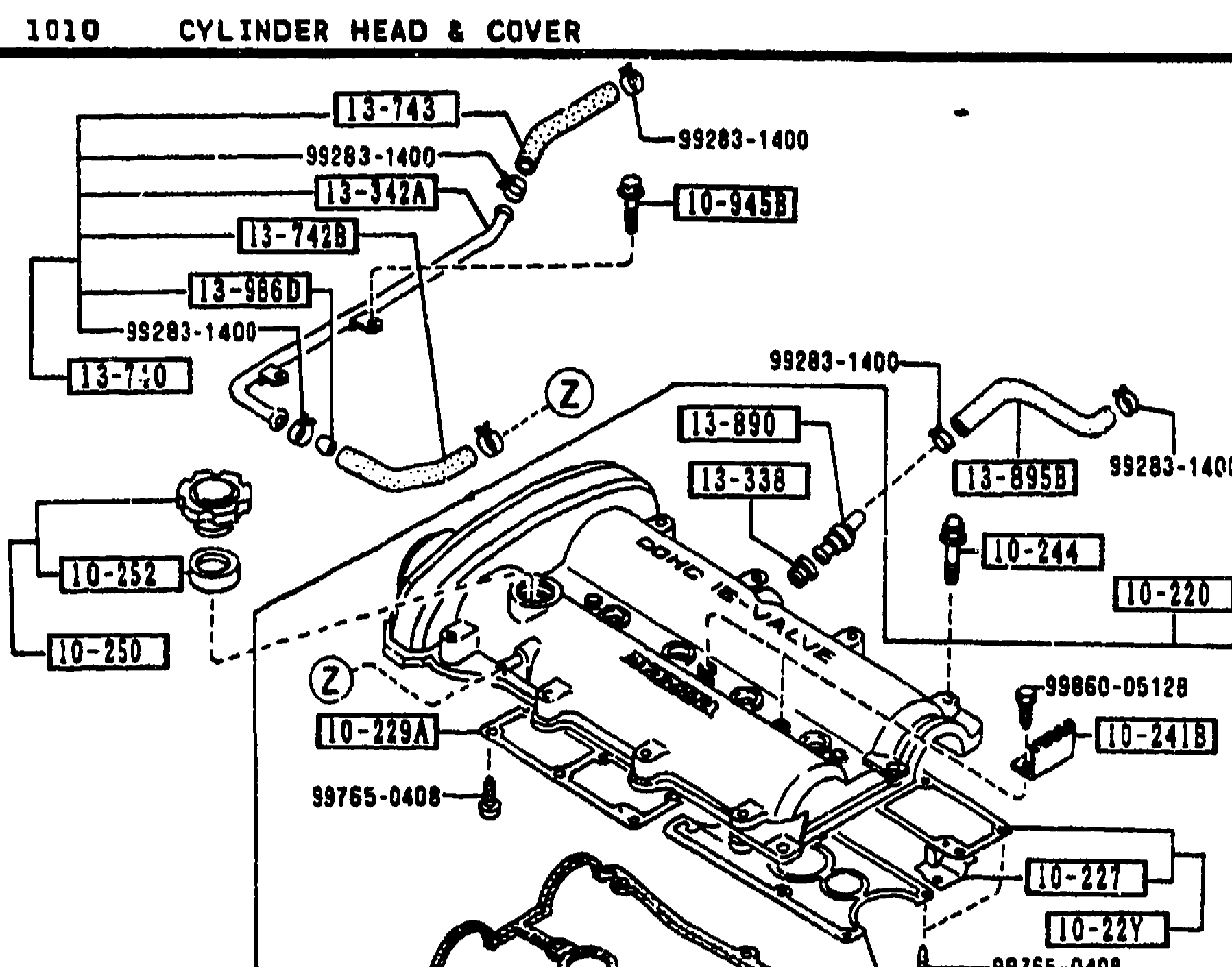
1010 CYLINDER HEAD & COVER
1-E3Exploded view of the B6 cylinder head & cover assembly, upper portion showing the cam cover (rocker cover) with PCV ventilation hoses (99283-1400) routed across the top, oil filler cap (10-250), valve cover gasket (10-255), and various bolts/washers (99060-0512R, 99765-0408, 10-249, 10-241, 10-237, 10-244, 10-247) numbered with balloon callouts referencing part rows in the table.
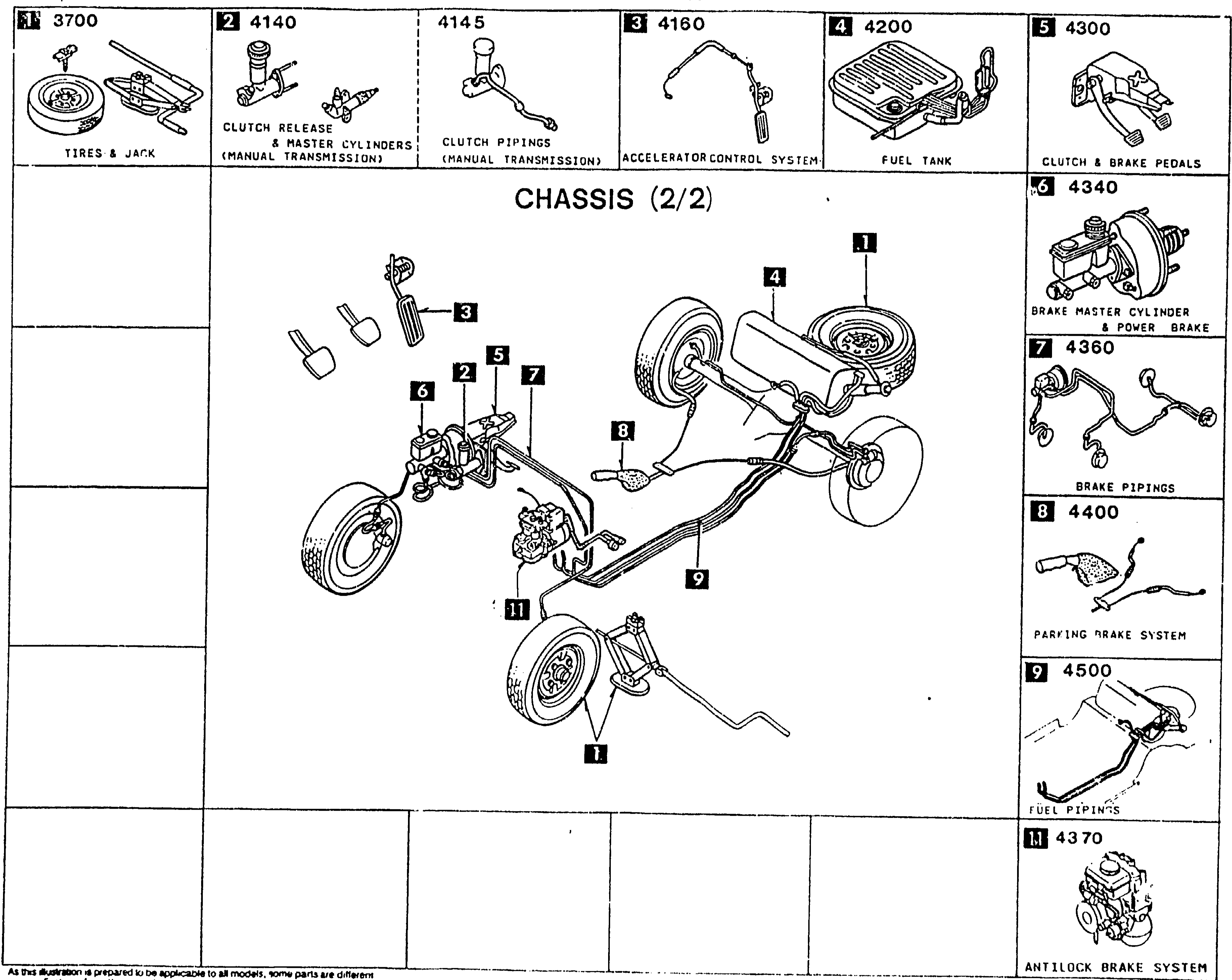
PICTORIAL INDEX — CHASSIS (2/2)
1-F 1Pictorial index for the CHASSIS (2/2) group of the MX-5 Parts Catalog. Central illustration: rolling chassis with wheels, brake lines, fuel lines, pedal box, master cylinder, parking brake cable, and accelerator-control system. Surrounding thumbnails labeled with section numbers and group names: 3700 Tires & jack, 4140 Clutch release & master cylinders (manual transmission), 4145 Clutch pipings (manual transmission), 4160 Accelerator control system, 4200 Fuel tank, 4300 Clutch & brake pedals, 4340 Brake master cylinder & power brake, 4360 Brake pipings, 4370 Antilock brake system, 4400 Parking brake system, 4500 Fuel pipings. Balloons (1–11) on the central illustration cross-reference each thumbnail to its position on the chassis.
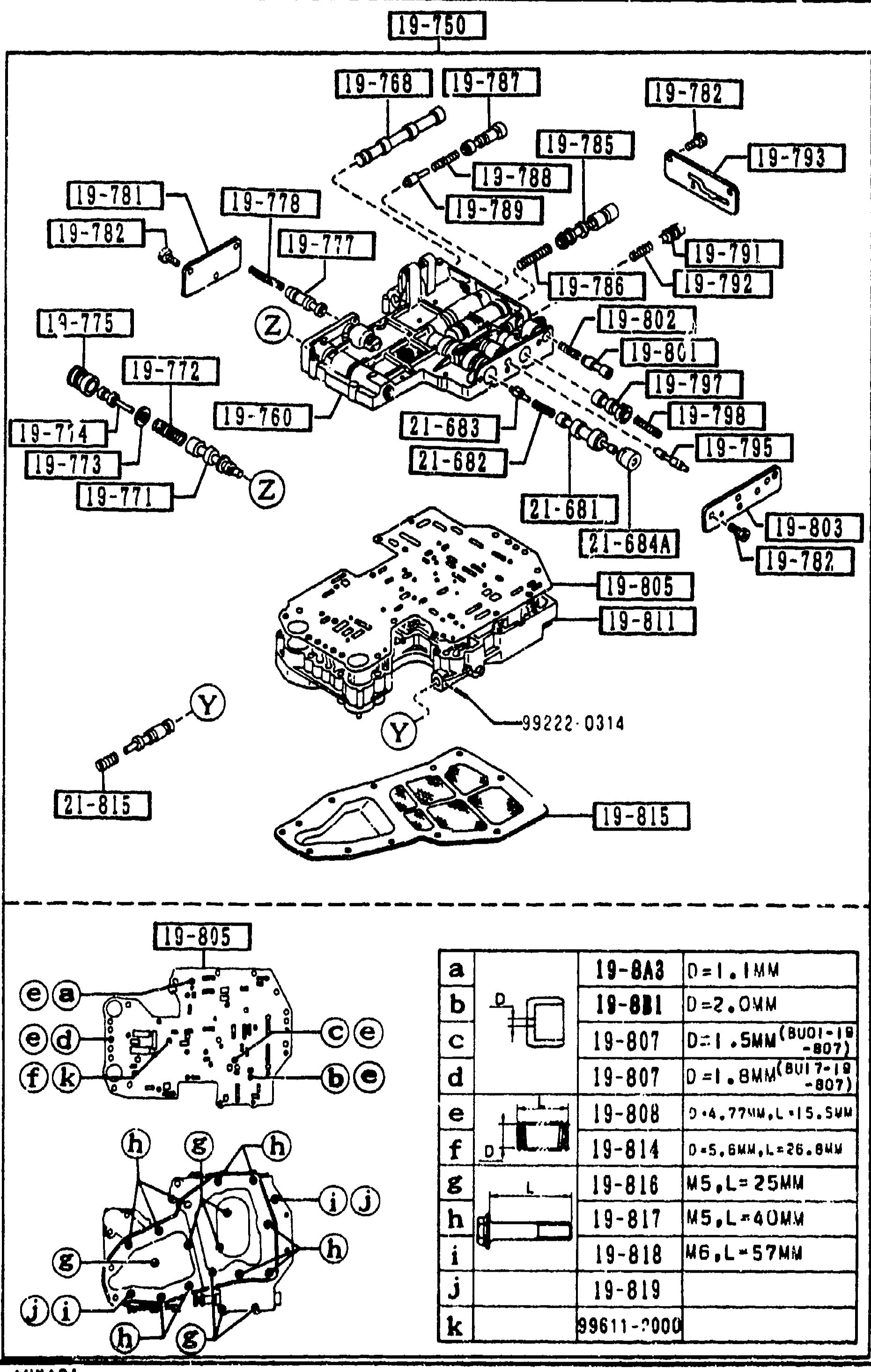
CONTROL VALVE (AUTOMATIC)
1-F 8Exploded view of the automatic-transmission CONTROL VALVE assembly (group 1925). Top diagram shows the full valve body with numbered balloon callouts for each component (e.g. 19-750 control valve body, 19-768/19-787 valves, 19-785/19-793 springs, 19-789/19-791/19-792 plugs, 19-777/19-778/19-781/19-782 separator plates, 19-801/19-802/19-803 valves, 19-775/19-771 components, 19-815 oil strainer at base, locator letters Y and Z). Bottom-left detail shows the lower valve body with callouts (e); bottom-right detail is a screw/bolt key panel (rows a-k) listing the sizes for items 19-8A3, 19-881, 19-807, 19-808, 19-814, 19-816, 19-817, 19-818, 19-819 and 99611-2000 with dimensions like D=1.1MM, D=1.5MM (BU01-19-807), L=25MM, L=40MM, L=57MM.
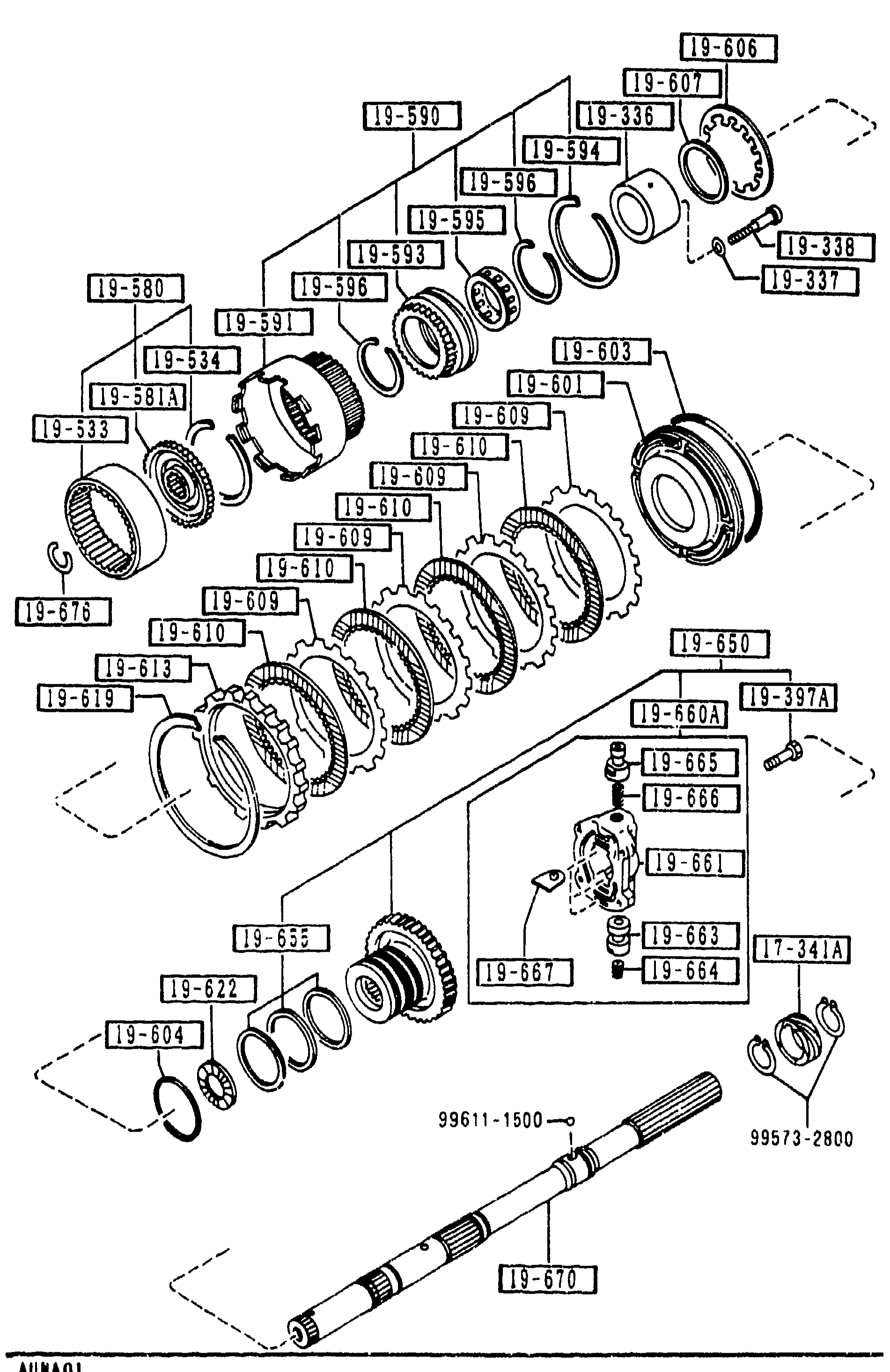
1940 GOVERNOR, LOW & REVERSE PISTON (AUTOMATIC) (CONT'D)
1-F 9Same governor/low & reverse piston exploded view (3rd repeat) with balloon callouts in 19-xxx series plus 17-341A. Highlights the governor body and valves at right (19-660A, 19-661, 19-665, 19-666, 19-667). Output shaft at bottom shows reference dimensions 99611-1500 and 99573-2800.
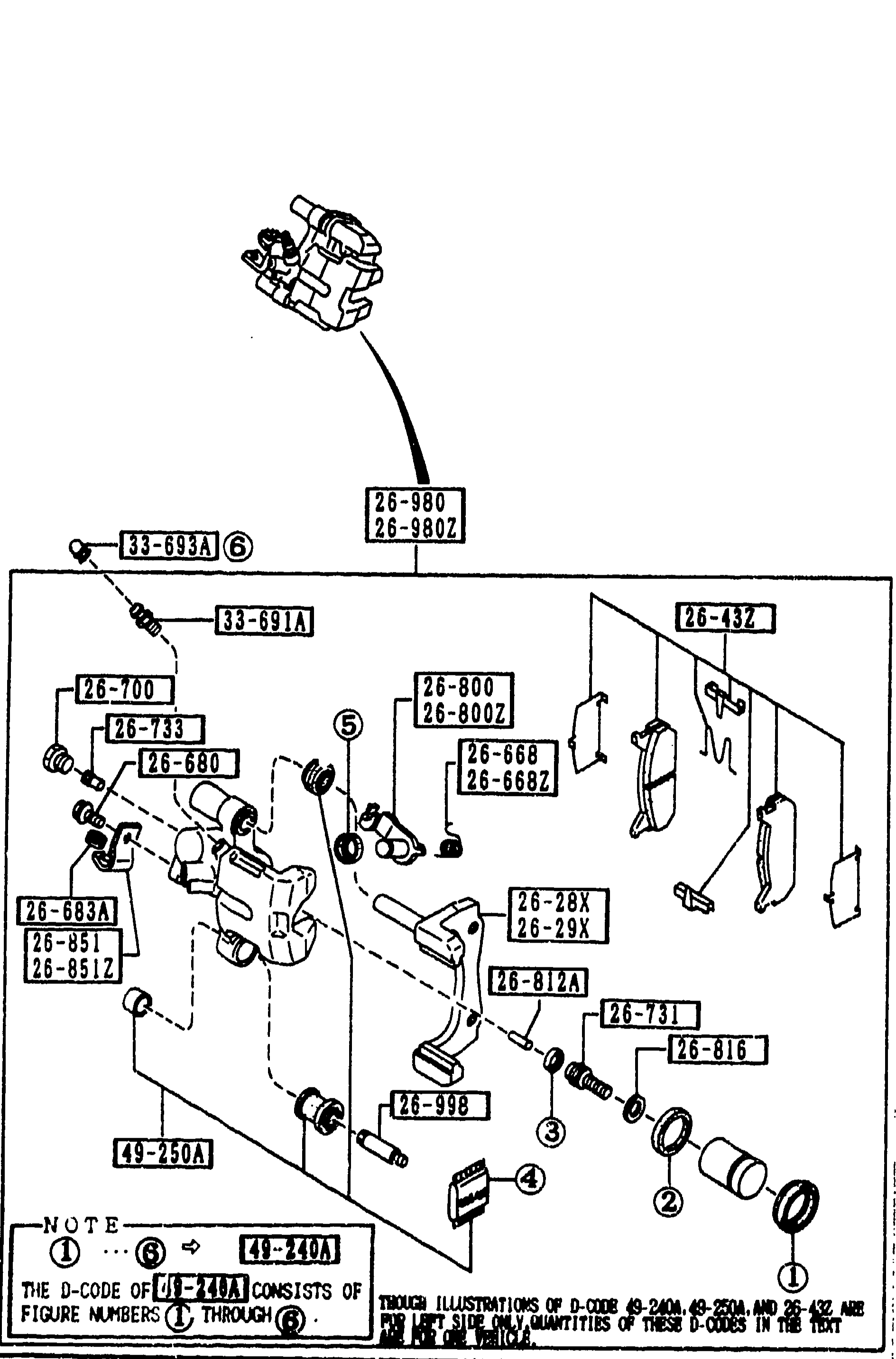
2610 REAR BRAKE MECHANISMS
1-F11Exploded view of the rear brake caliper assembly (left half of page). Top shows the caliper body and pad insertion; main view shows the dismantled caliper: mounting brackets 26-28X/26-29X, 33-693A bolt, 33-691A bolt/pin, 26-700 plug/screw, 26-680 bolt, 26-668/26-668Z springs (R/L lever), 26-731 spindle (adjuster), 26-43Z pad set (asbestos), 26-432 component, 26-800/26-800Z lever (R/L operating), 26-851/26-851Z, 26-683A protector, 26-812A push rod, 26-816 snap ring, 26-998 with 49-250A tool, and 26-980/26-980Z lever assembly at top. A note at bottom-left mentions D-code 49-2404, 49-2504, 26-432 and tool 49-3404.
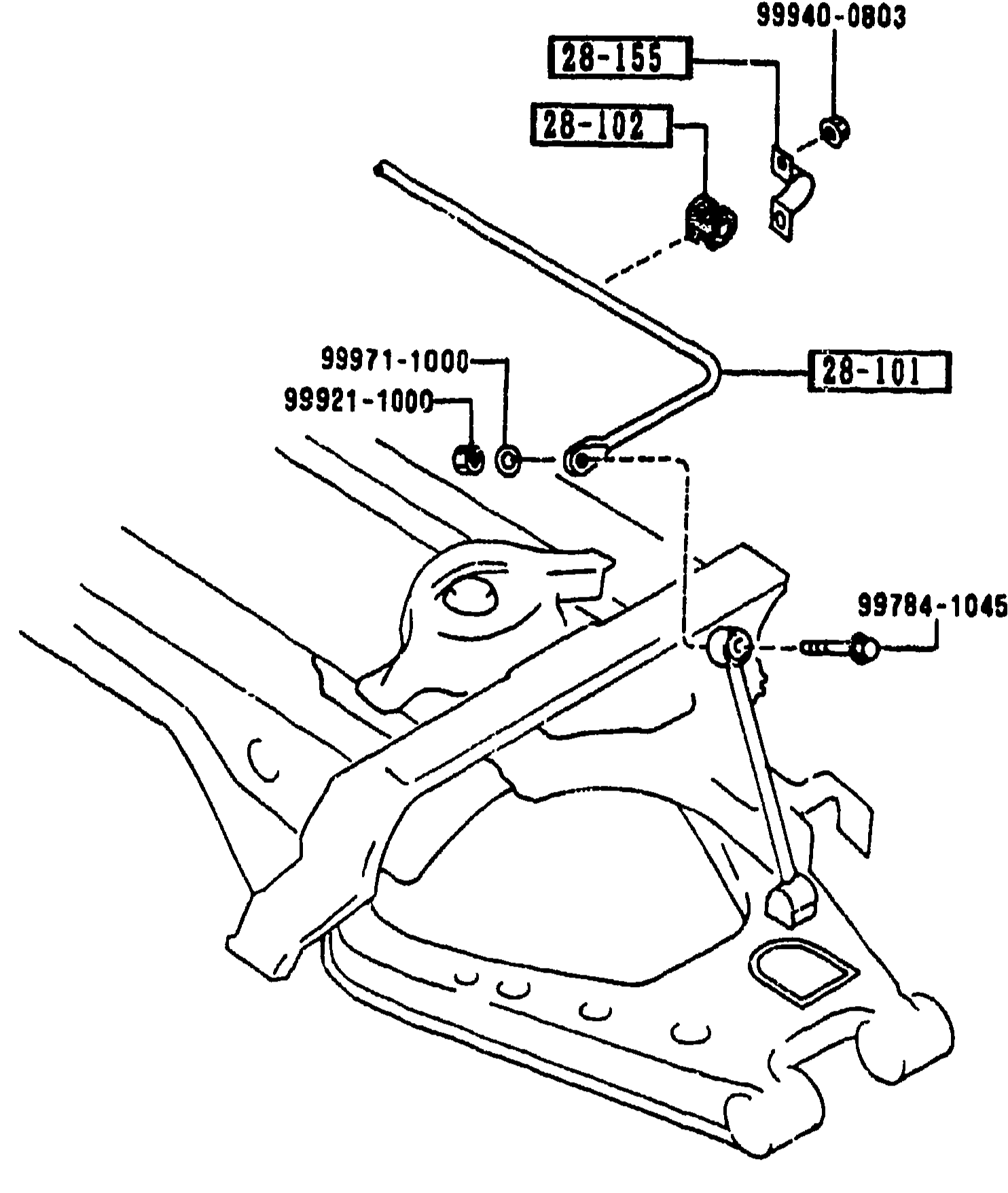
REAR STABILIZER
1-F12Exploded view of the rear stabilizer bar mounted across the rear sub-frame. Visible callouts: stabilizer bar (28-101), bush (28-102), bracket plate (28-155), bracket bolt (99940-0803), end-link nut (99971-1000), washer (99921-1000), and pivot bolt (99784-1045).
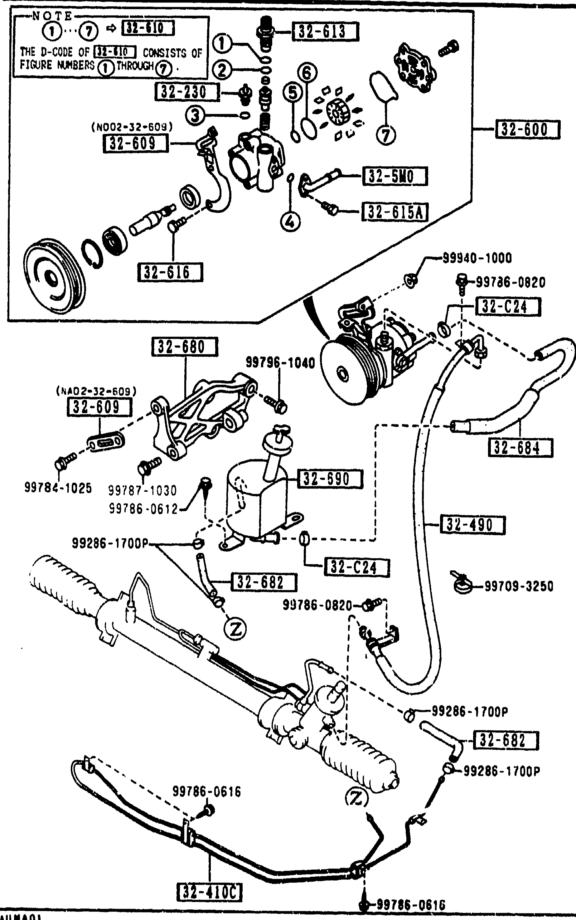
POWER STEERING SYSTEM
1-F13Exploded view of the power steering system showing pump assembly with bracket and pulley, vane pump (32-600), reservoir/tank, pressure hoses (32-490), suction pipe (32-5M0), return pipe (32-410C), steering rack/gear with mounting hardware, clamps, and various seals/bolts. Component group code 32-610 (D-CODE NOTE at top-left). Balloon callouts 1 through 7 (some hidden) identify subcomponents.
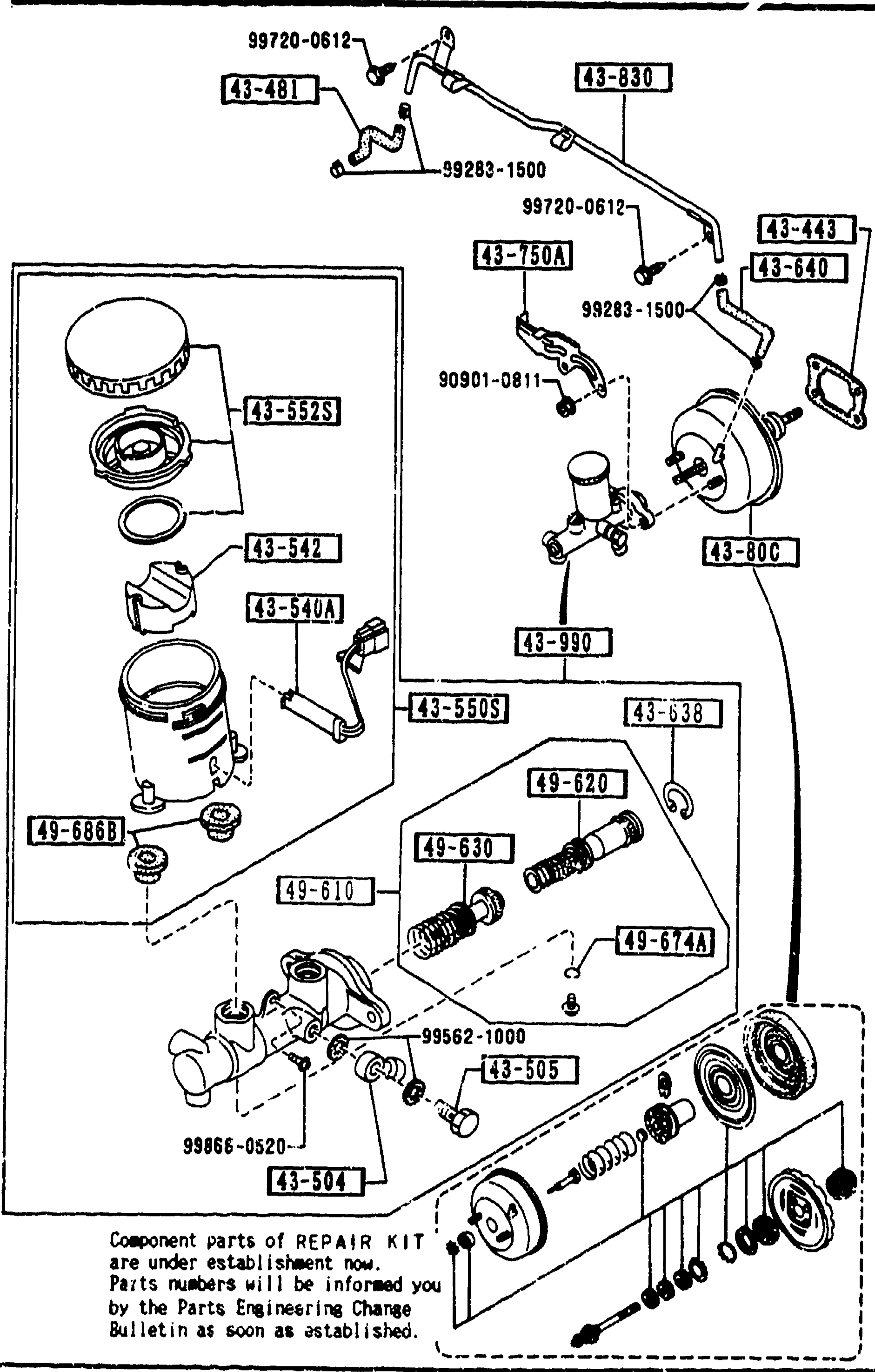
BRAKE MASTER CYLINDER & POWER BRAKE
1-F16Exploded view of the brake master cylinder and power brake (vacuum servo) assembly. Shows vacuum pipes routed across the top with retaining clips, the reservoir tank with cap and float on the upper-left, the tandem master cylinder body, the power brake (vacuum booster) on the right, and at the bottom a row of internal repair-kit parts (pistons, rings, bushes, P.B. valve holder). Balloon callouts identify part-group numbers in boxes (43-xxx and 49-xxx series).
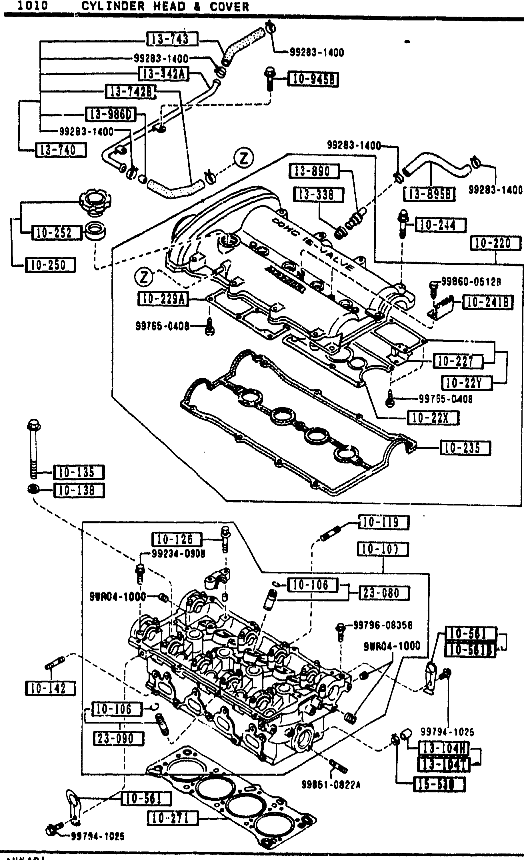
1010 CYLINDER HEAD & COVER
1-F3Exploded view of B6 cylinder head assembly continuation. Upper portion shows cam cover/rocker cover with PCV ventilation hoses (13-740, 13-742A, 13-743) routed across the top, oil-filler cap and PCV valve assemblies (13-890), connector hose (13-895B) and orifice (13-97). Lower portion shows bare cylinder head with valve guides (10-280, 10-290), water-hose clamp (15-538), and assorted bolts (99794-1025, 99851-0822A, 99796-08258, 99834-0908, 99804-1000) numbered with balloon callouts referencing the parts table.
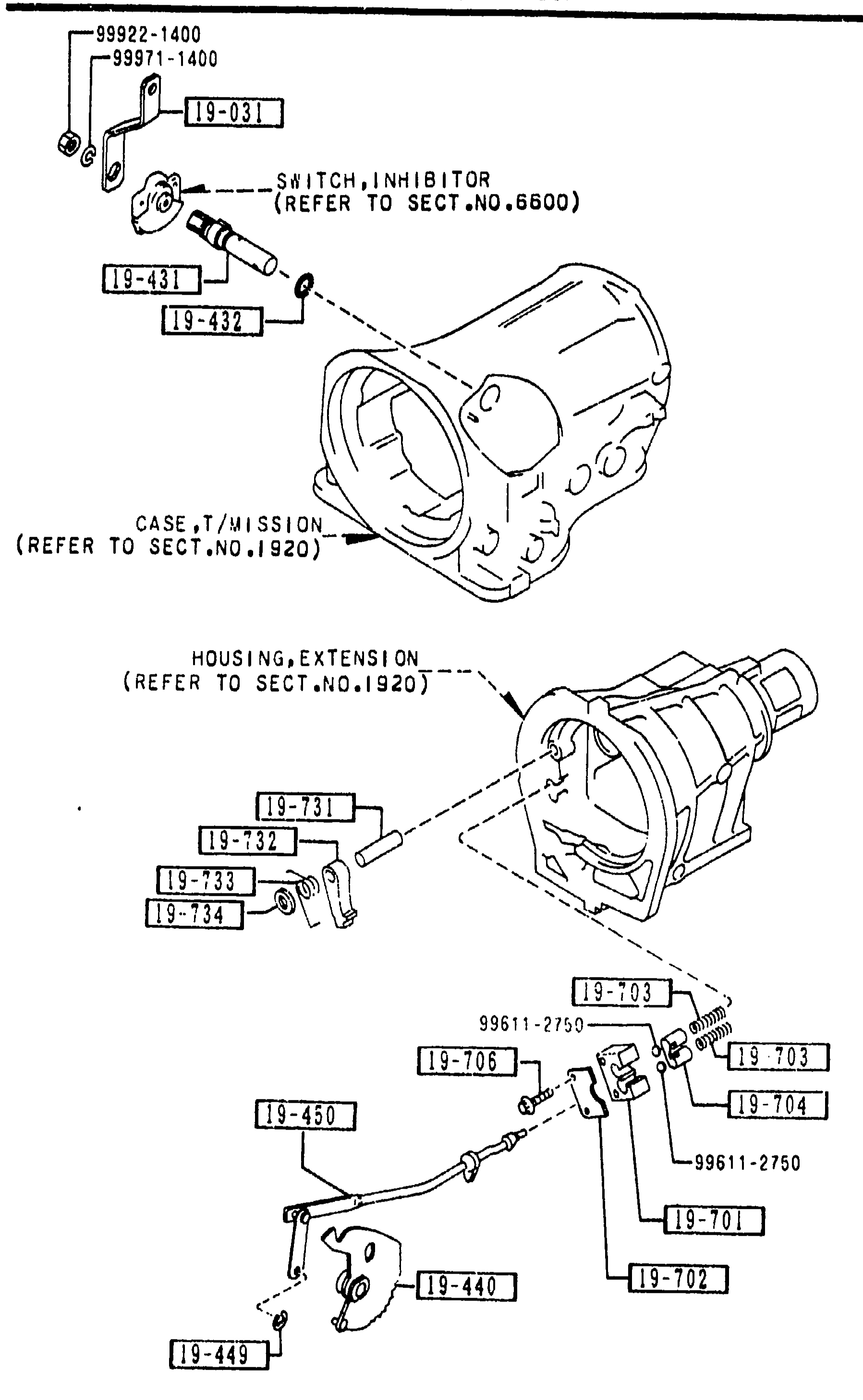
1950 MANUAL LINKAGE SYSTEM (AUTOMATIC)
1-G 9Exploded view of the automatic transmission manual linkage system. Top shows transmission case (CASE,T/MISSION — REFER TO SECT.NO.1920) with the inhibitor switch (SWITCH,INHIBITOR — REFER TO SECT.NO.6600). Lower shows the extension housing (HOUSING,EXTENSION — REFER TO SECT.NO.1920) with parking pawl mechanism. Reference dimensions 99922-1400, 99971-1400, and 99611-2750 visible. Balloon callouts: 19-031, 19-431, 19-432, 19-440, 19-449, 19-450, 19-701, 19-702, 19-703, 19-704, 19-706, 19-731, 19-732, 19-733, 19-734. Figure-ref 'AUNA01' bottom-left.
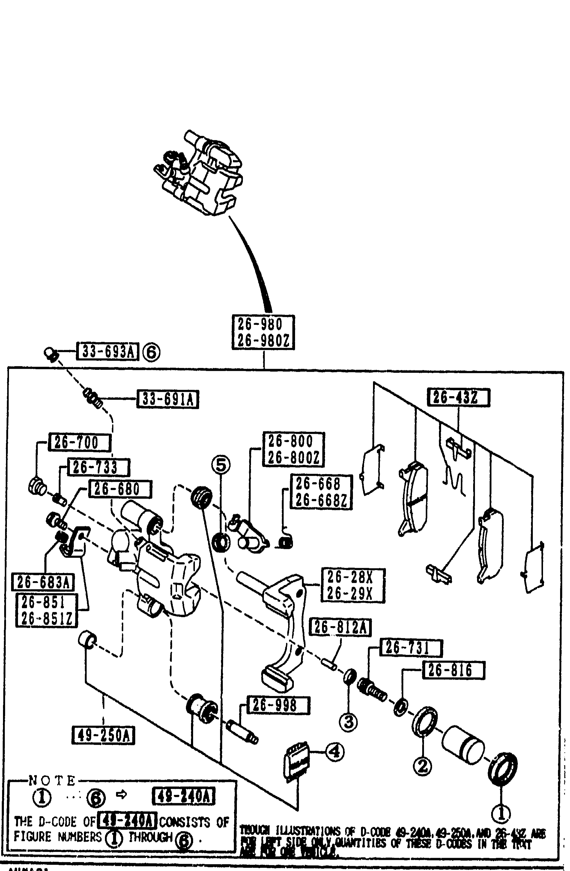
2610 REAR BRAKE MECHANISMS (continued)
1-G11Continuation exploded view of the rear brake caliper, same artwork as the previous page but with the second-page parts list. Shows the caliper body, mount, and dismantled internals: 26-980/26-980Z calipers (R/L), 33-693A bolt, 33-691A guide pin, 26-700 plug screw, 26-680 bolt, 26-668/26-668Z lever springs, 26-432 pad shim, 26-800/26-800Z operating levers, 26-683A protector, 26-851/26-851Z brackets (R/L) for cable, 26-812A push rod, 26-731 spindle, 26-816 snap ring, 26-998 guide pin, 49-250A SST. The exact same exploded view appears on the previous page; this page lists items continued from there.
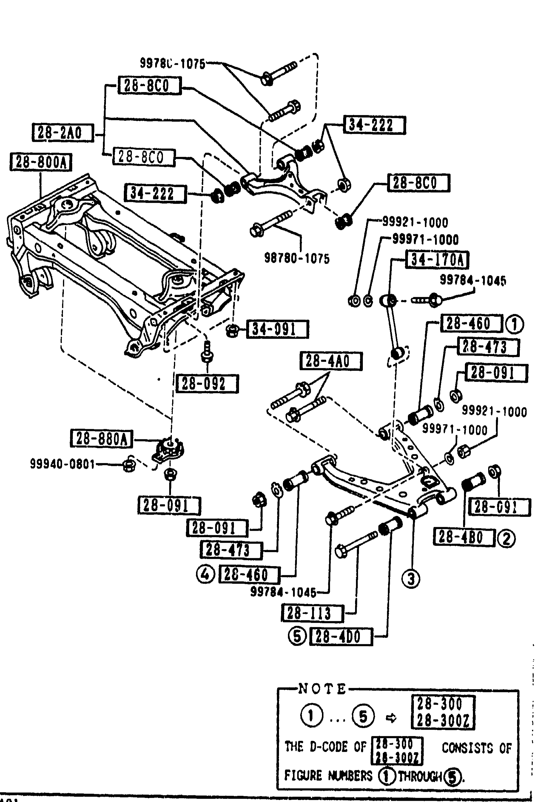
REAR LOWER ARMS & SUB FRAME
1-G12Exploded view of the rear sub-frame (cross member 28-800A), upper and lower control arms with bushings, control links, and associated hardware. Visible callouts include upper-rear arm (28-2A0), lower-rear arms R/L (28-300, 28-300Z), bolts, nuts, and rubber bushings (28-4A0, 28-4B0, 28-4D0, 28-460, 28-8C0). A NOTE box at the bottom states that the D-code of 28-300/28-300Z parts consists of figure numbers 1 through 5.
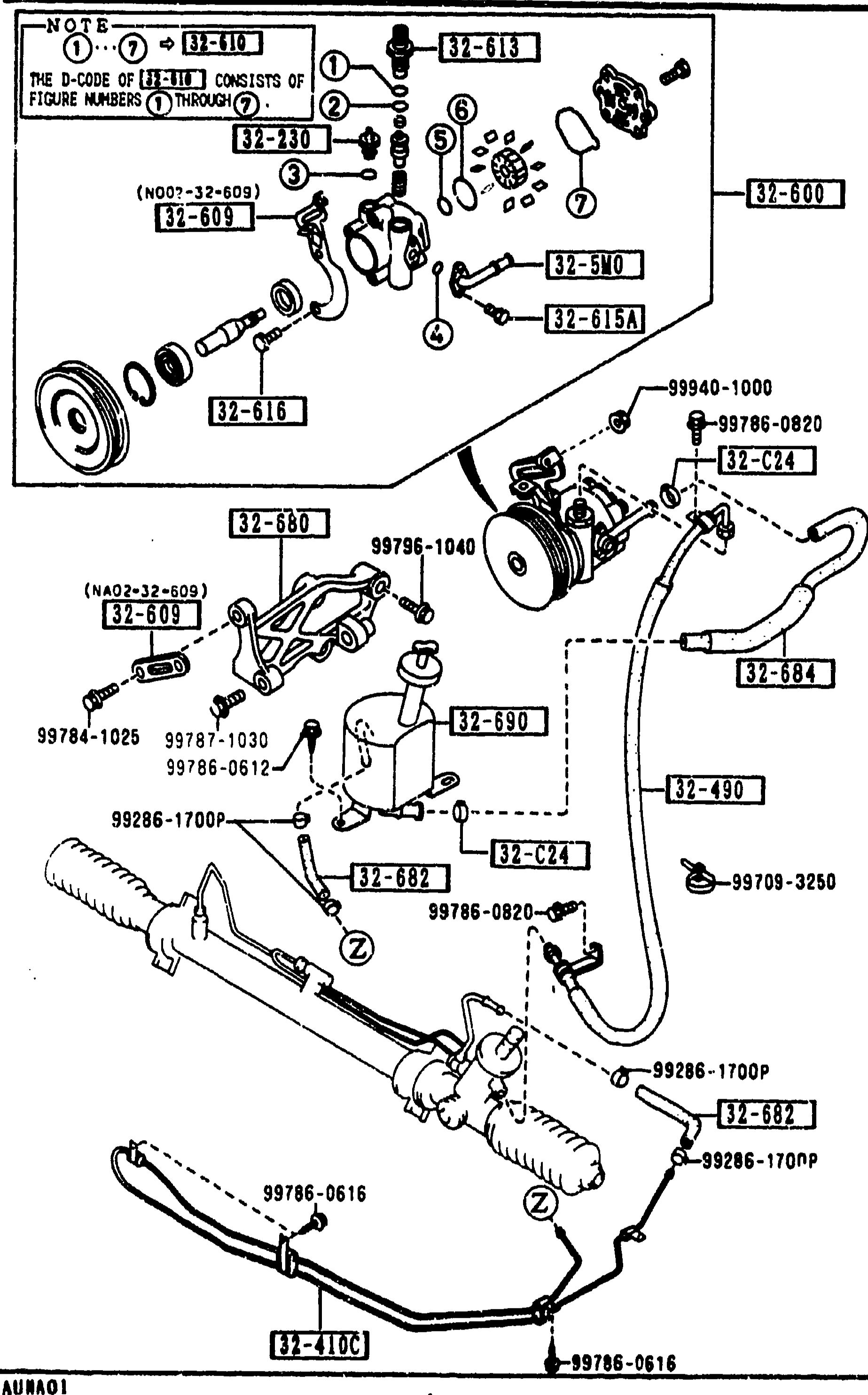
POWER STEERING SYSTEM
1-G13Exploded view of power steering pump bracket, hoses, and reservoir tank (same composite exploded-view as page 1-F13). Shows pump assembly with bracket 32-680, return hoses 32-682 and 32-684, tank 32-690, plus all related fasteners, clips and pipe routing to the steering rack.
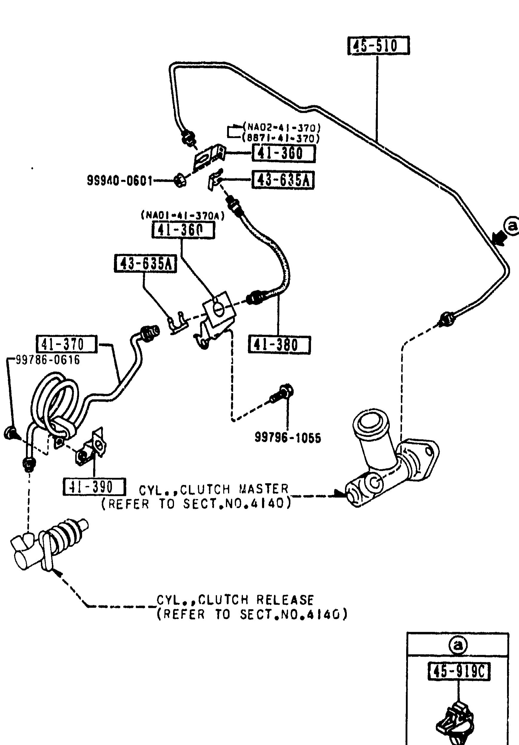
4145 CLUTCH PIPINGS (MANUAL TRANSMISSION)
1-G15Exploded view of the clutch hydraulic piping system (manual transmission). Shows the clutch pipe routing from the clutch master cylinder (callout 41-390, references SECT.NO.4140) along the firewall to the slave/release cylinder (callout, references SECT.NO.4140), with the long upper pipe 45-510, intermediate hose 41-380 (flexible), clutch holders 41-360 and 41-390, clip 43-635A (×2), and pipe 41-370. A separate detail at bottom-right shows clip 45-919C in isolation (callout 'a'). Fasteners include 99940-0601, 99796-1055, 99786-0616.
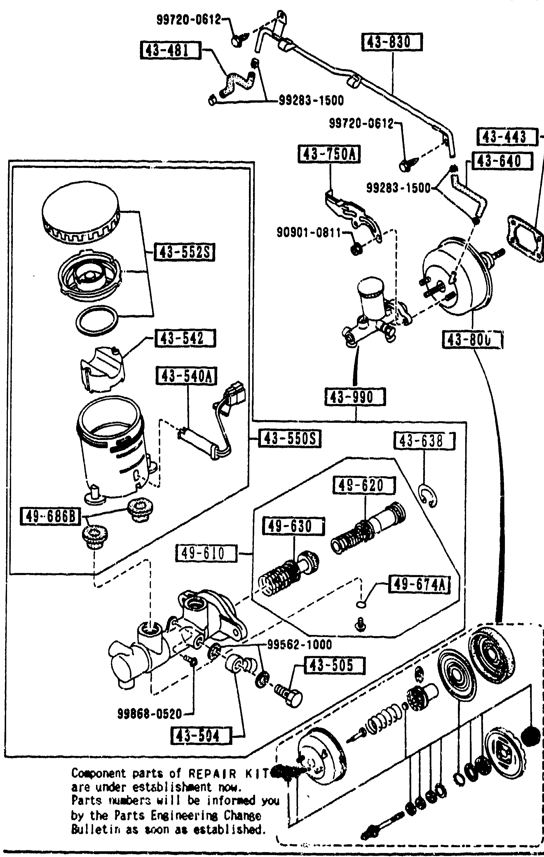
BRAKE MASTER CYLINDER & POWER BRAKE
1-G16Sheet 2 of the brake master cylinder and power brake assembly — same exploded view as the previous page repeated on the left to key part-number balloons to the additional rows on the right. Shows the same reservoir-tank, tandem master cylinder, vacuum booster and internal repair-kit components with callouts for 43-830, 43-990, 49-610, 49-620, 49-630, 49-674A and 49-636B.
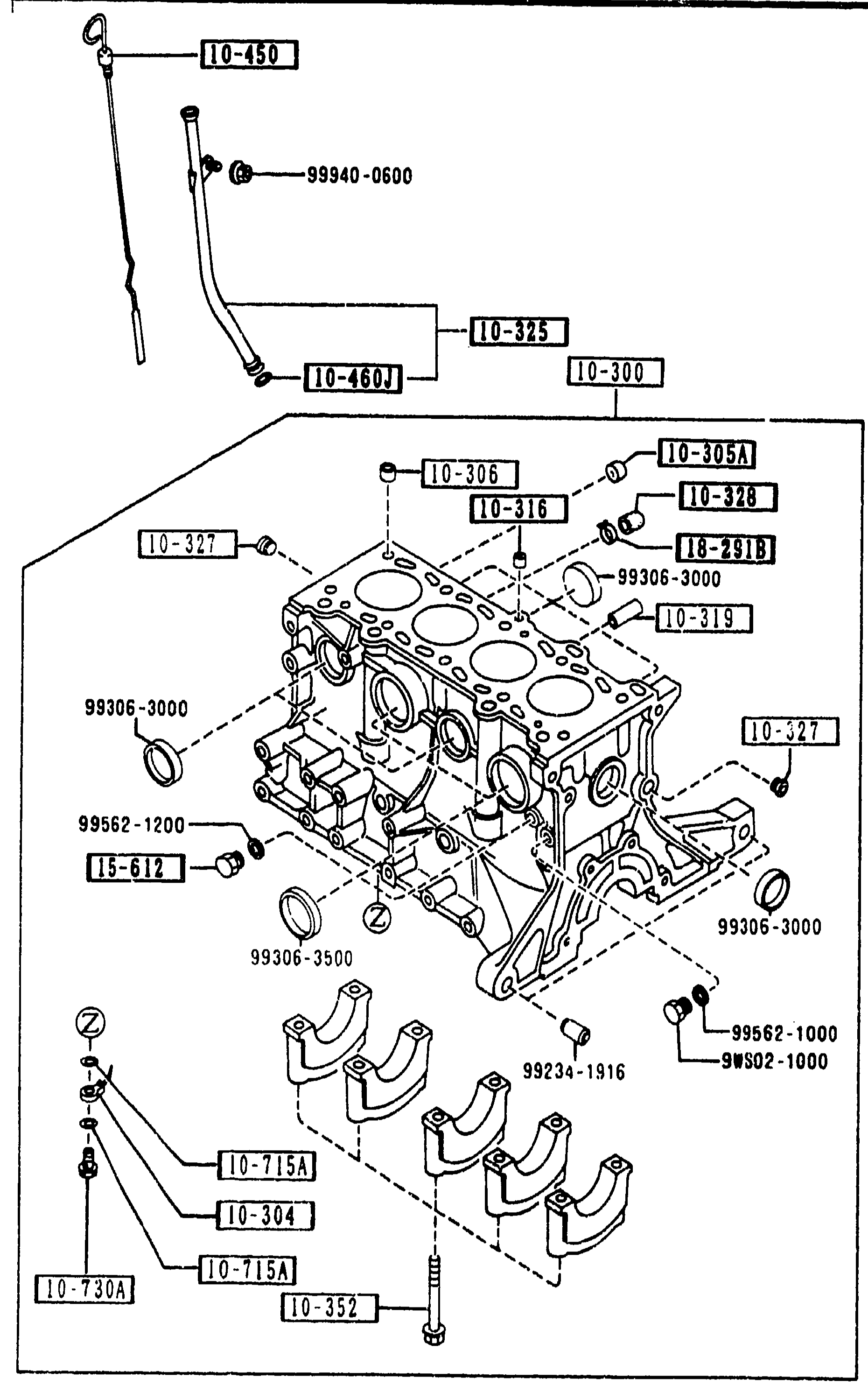
1030 CYLINDER BLOCK
1-G3Exploded view of the B6 cylinder block. Shows the dipstick & guide tube assembly (10-450, 10-460J), oil-pump pickup tube (10-325, 10-466J), main bearing caps with bolts (99306-3000, 10-352), tubular pins/dowels (10-306), oil-control plug and joint (10-316, 10-319), oil-jet plugs (10-305A, 10-308), bearing-cap bolts (10-352) and the oil-level gauge guide (10-440). The block is shown from the cam-cover side with the front of the engine to the left.
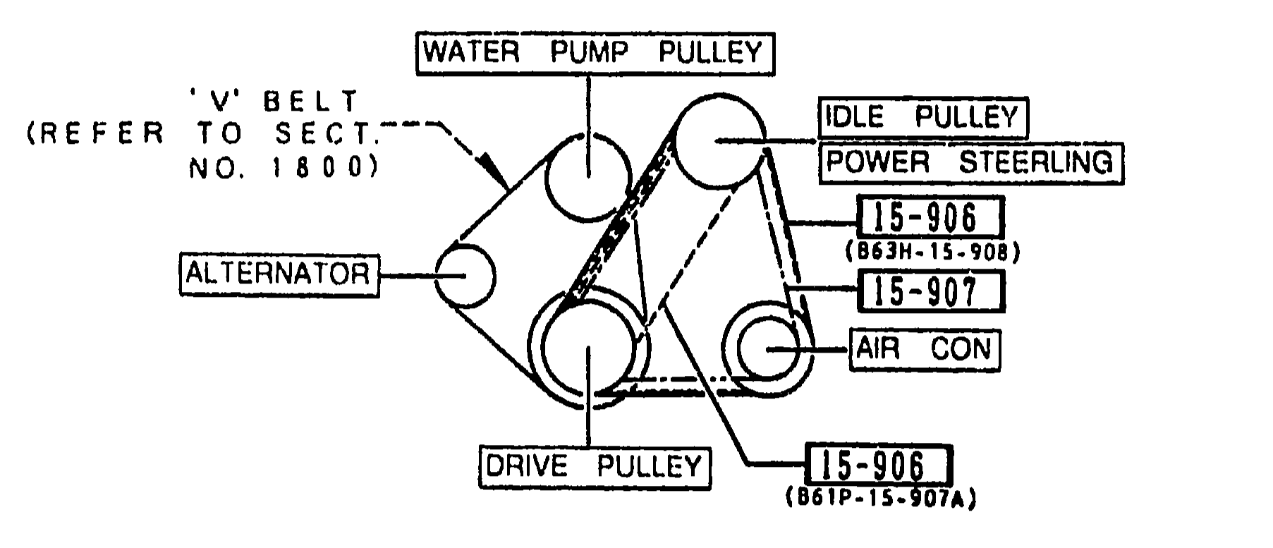
1580 BRACKET, PULLEY & BELT
1-G5Top diagram: V-belt drive layout for the MX-5 NA, showing the WATER PUMP PULLEY at the top, ALTERNATOR pulley to the left, IDLE PULLEY (POWER STEERING) to the right and DRIVE PULLEY at the bottom. Belt 'V' refers to Sect. No. 1800. Belt callouts 15-906 (B61P-15-907A) and 15-907 mark the two belt routes; AIR CON branch on the right.
1580 BRACKET, PULLEY & BELT
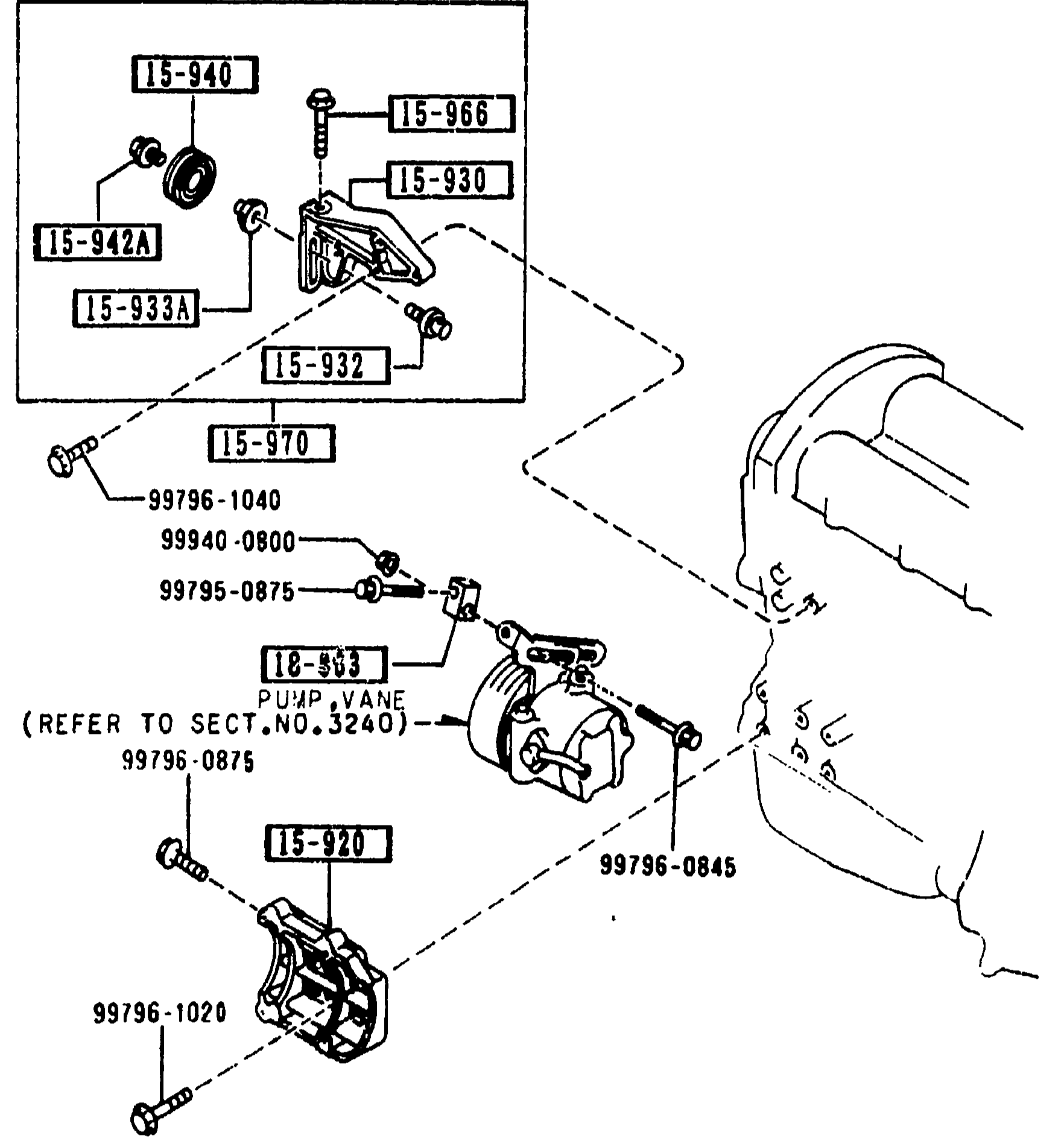
1-G5Lower exploded view: idle-pulley bracket and power-steering pump bracket assembly. Callouts identify pulley idle 15-940, screw bolt 15-966, bracket idle pulley 15-930, collar 15-933A/15-942A, shaft pulley 15-932, pulley idle 15-970, bolt adjust 18-303, plus screws 99796-1040, 99940-0800, 99795-0875, 99796-0875, 99796-0845, 99796-1020, 99796-0612. Pump vane 18-303 refers to Sect. No. 3240. Vehicle silhouette outline visible at the right.
1950 MANUAL LINKAGE SYSTEM (AUTOMATIC) (CONT'D)
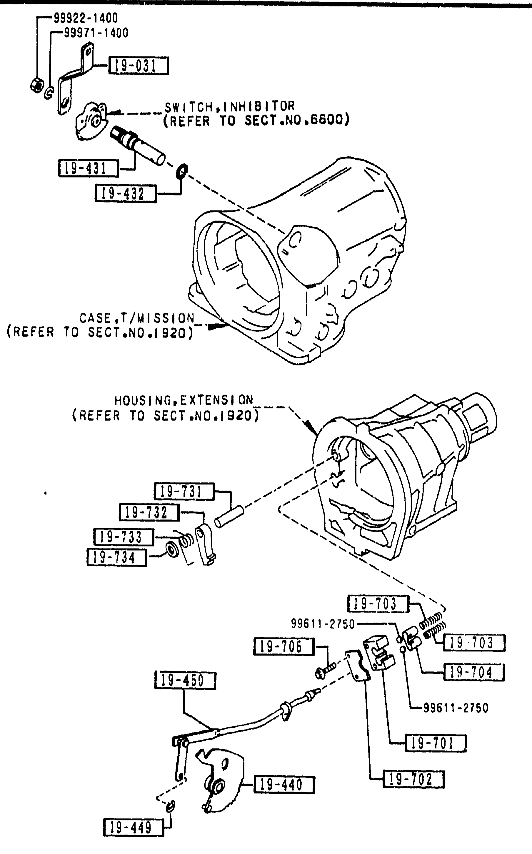
1-H 9Same automatic-transmission manual linkage exploded view as 1-G 9. Top: transmission case with inhibitor switch (REFER TO SECT.NO.6600) and shaft/ring. Bottom: extension housing (REFER TO SECT.NO.1920) with parking pawl and rod assembly. Reference dimensions 99922-1400, 99971-1400, 99611-2750. Balloon callouts cover 19-031, 19-431, 19-432, 19-440, 19-449, 19-450, 19-701, 19-702, 19-703, 19-704, 19-706, 19-731, 19-732, 19-733, 19-734.
2710 REAR DIFFERENTIALS (NORMAL DIFF.)
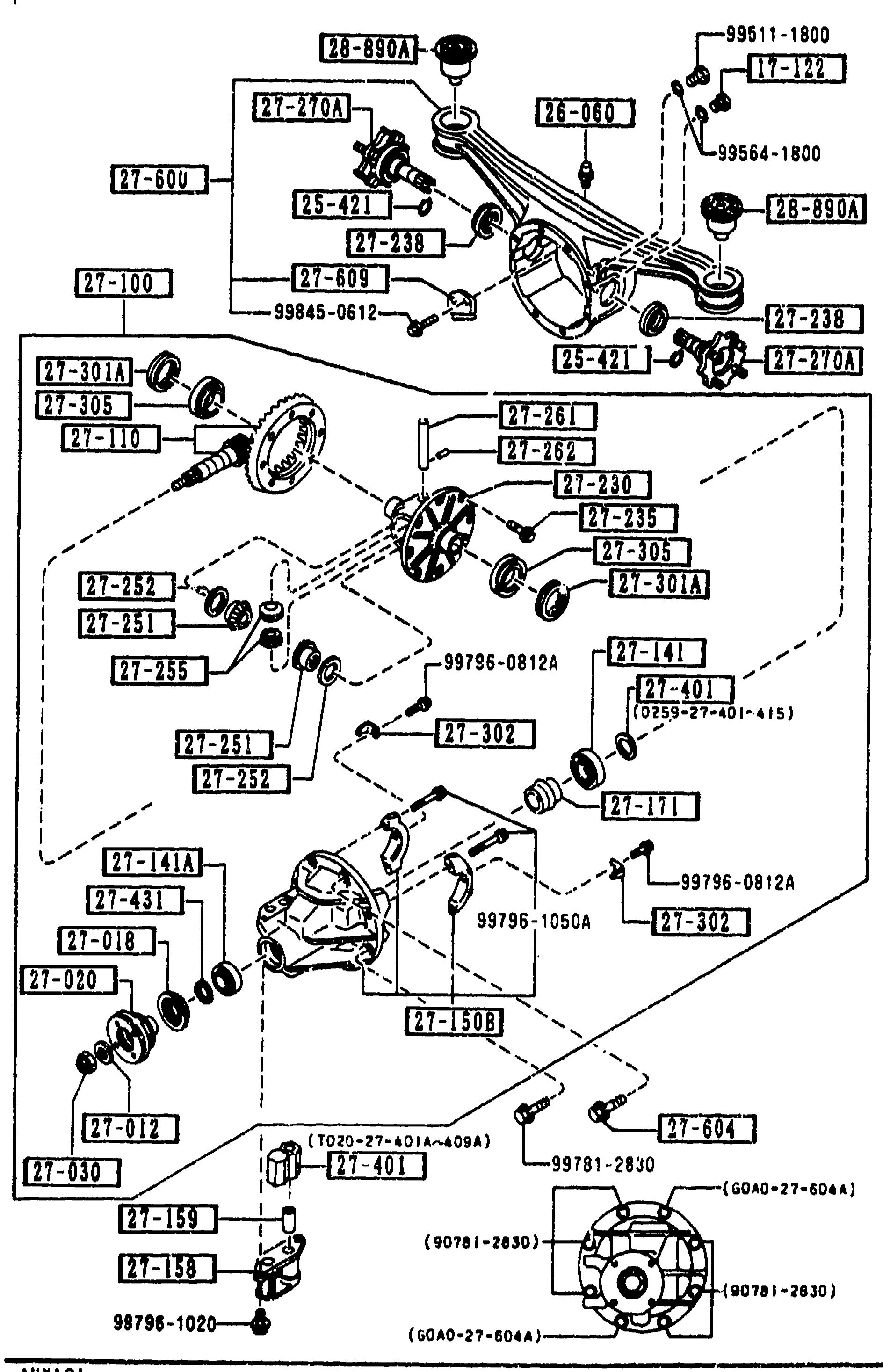
1-H11Dense exploded view of the normal rear-differential assembly (left half of page). Top: differential carrier with cover and bolts (17-122 plug magnet, 27-421 clip, 26-840 breather, 27-012 washer, 27-149 oil seal, 27-120A companion flange, 27-130 lock nut). Middle: pinion bearings, ring gear and final-drive components (27-100 driving & diff., 27-110 final gear set R=4.300, 27-141 pinion bearing, 27-141A pinion bearing). Bottom: differential carrier housing (27-150B/27-150C carrier, differential, with hardware 99786-08124, 99786-1056A, 99781-2630 etc.).
2830 REAR LOWER ARMS & SUB FRAME
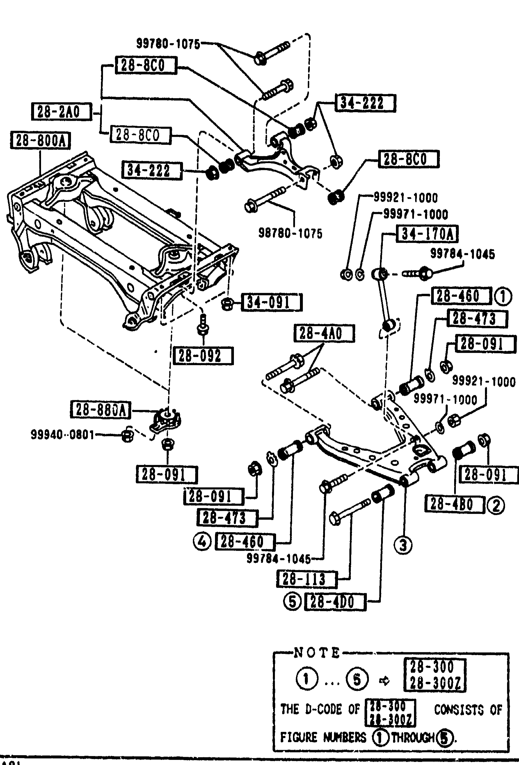
1-H12Exploded view of the rear lower arms and sub-frame assembly. Shows the rear sub-frame crossmember (left), upper control arms (top, 28-8C0 type), lower control arms (28-4A0 type), stabilizer control links (34-170A), bushings (28-091, 28-473, 28-460), and associated hardware (34-091 nut, 34-222 nut, 99780-1075, 99921-1000, 99971-1000, 99784-1045, 28-880A ball-joint type, 99940-0801, 28-092, 28-113, 28-400, 28-300, 28-300C). NOTE block at lower-right: 'THE D-CODE OF [28-300][28-300C] CONSISTS OF FIGURE NUMBERS (1) THROUGH (5)' with callout circles (1) through (5) shown on the figure.
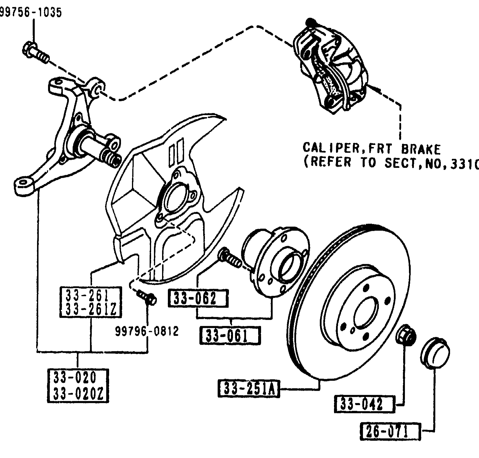
FRONT AXLE
1-H13Exploded view of the front axle / front brake hub assembly showing steering knuckle, wheel hub, brake disc (ventilated), front brake caliper (labeled 'CALIPER, FRT BRAKE (REFER TO SECT.NO.3310)'), dust covers, hub cap and mounting hardware. Callouts: 99756-1035 (caliper bolt), 99796-0812 (bolt), 33-261/33-261Z (dust covers L/R), 33-062 (hub bolt), 33-061 (wheel hub), 33-251A (disc plate), 33-042 (nut/washer), 26-071 (hub cap), 33-020/33-020Z (steering knuckle R/L).
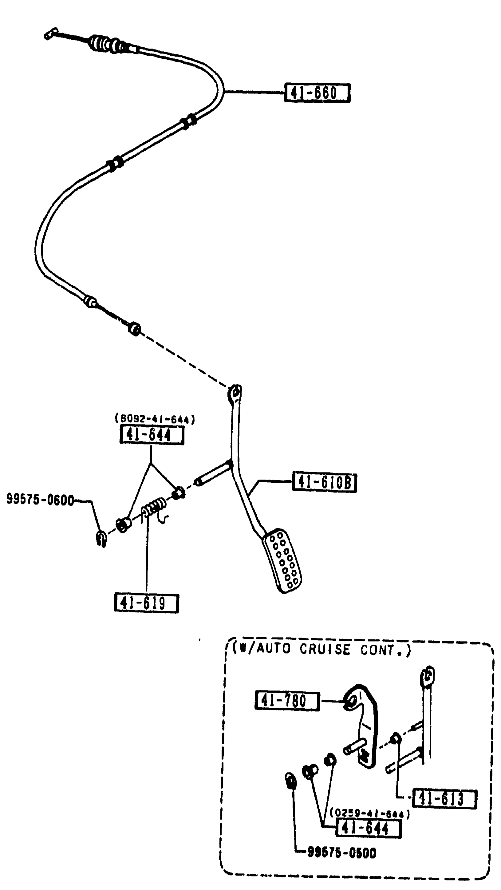
4160 ACCELERATOR CONTROL SYSTEM
1-H15Exploded view of the accelerator control system. Shows the accelerator pedal & arm (callout 41-610B, with pedal pad), the accelerator cable (41-660) routed from the pedal arm up to the throttle body, return spring (41-619), bush (41-644), roller (41-613, package option w/ auto cruise control), small washer (99575-0600). An inset detail at lower-left labeled '(W/AUTO CRUISE CONT.)' shows the accelerator lever (41-780) with bush (41-644), roller bracket (41-613) and additional fastener (99575-0500).
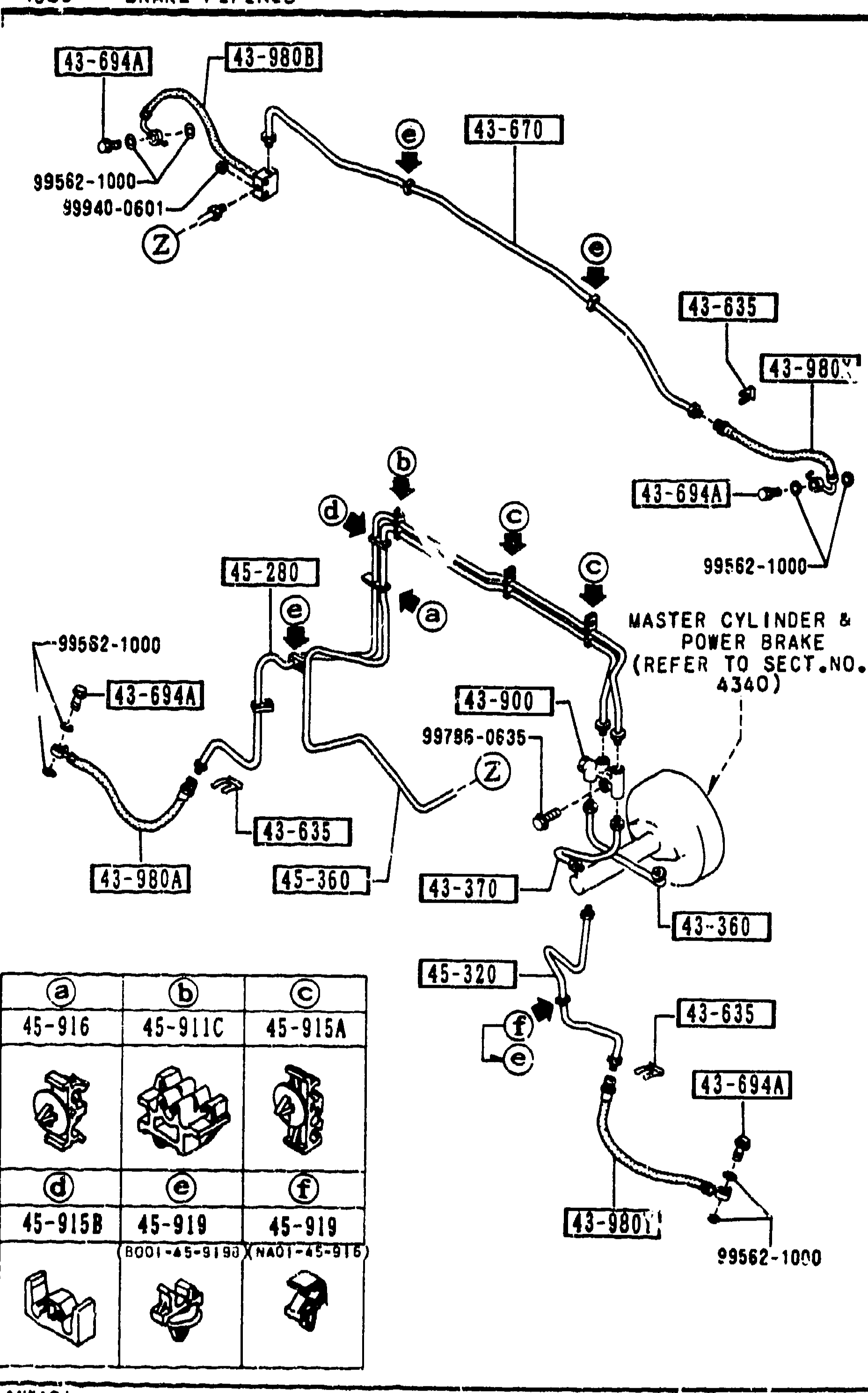
BRAKE PIPINGS
1-H16Vehicle-underbody exploded view of the brake pipings: hard pipes routed from the master cylinder/power brake assembly (top centre, callout to SECT. NO. 4340) out to the four wheels via flexible hoses, the dual proportioning valve and intermediate joints. A subset of pipe-clip callouts (a-f) in the lower-left inset indexes six clip-shape variants (45-916, 45-911C, 45-915A, 45-915B, 45-919, 45-919).
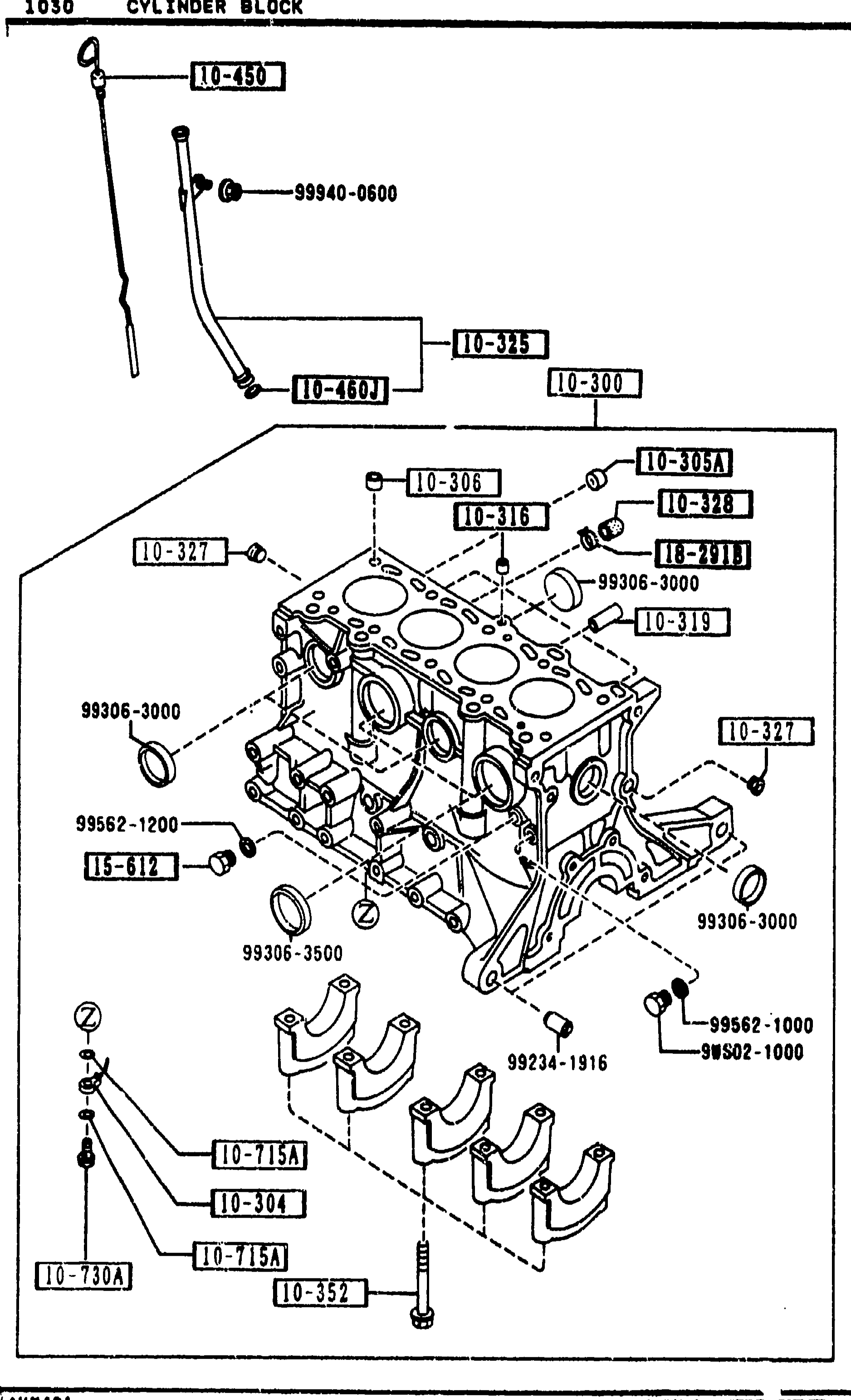
1030 -2 M CYLINDER BLOCK
1-H3Exploded view of B6 cylinder block — same drawing reprinted to carry the parts continuation. Shows dipstick & guide tube (10-450, 10-460J), oil-pump pickup (10-325), main bearing caps (10-352) with bolts (99306-3000), oil-jet plugs (10-305A, 10-308), tubular pins (10-306), oil-control plug & joint (10-316, 10-319), blind plug (10-327), oil-jet seal (10-715A) and matching 10-730A / 10-304 valve oil-jet assembly at lower-left.
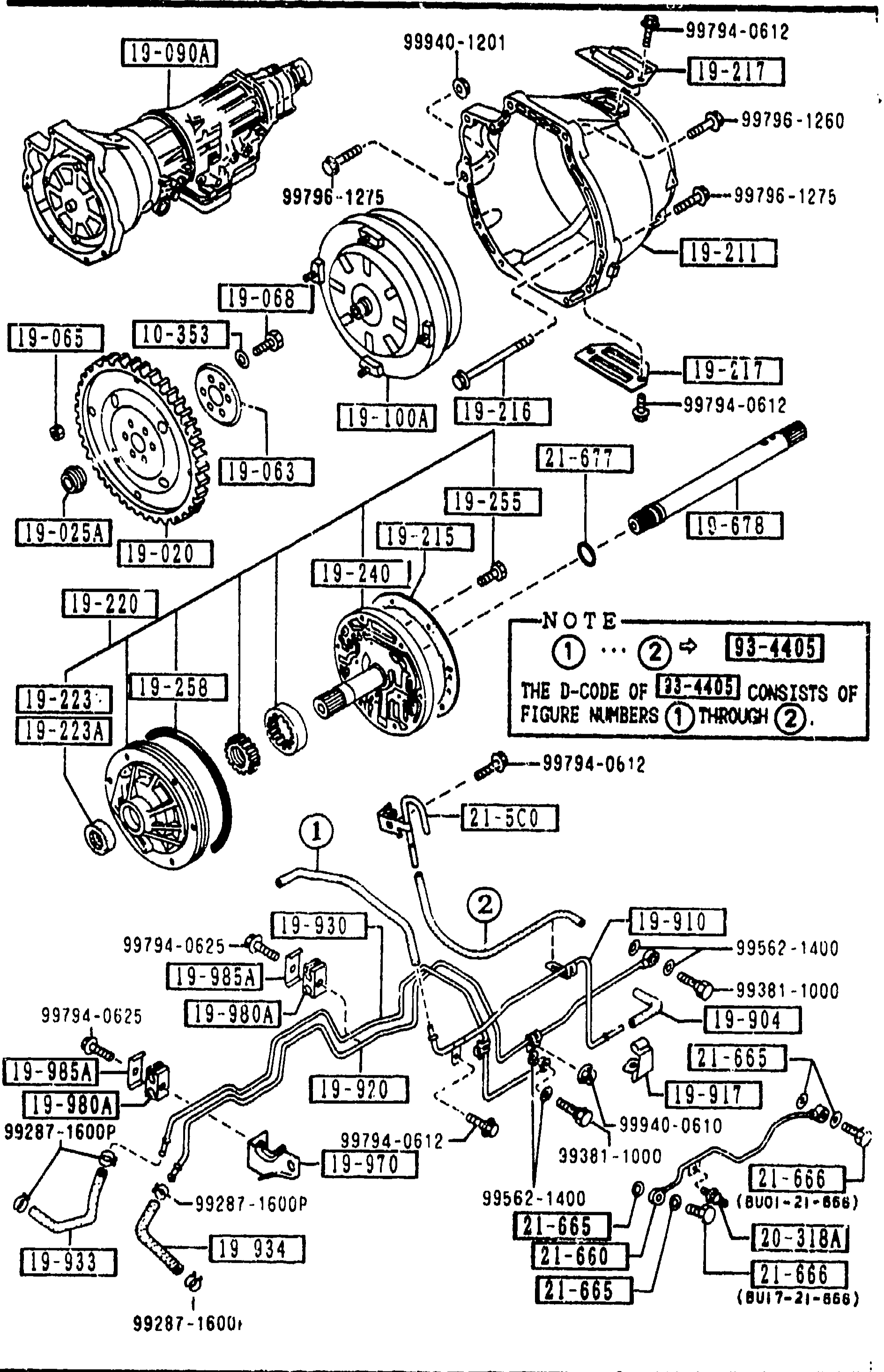
1910 TORQUE CONVERTER, OIL PUMP & PIPINGS (AUTOMATIC)
1-i 7Exploded view of the automatic transmission torque converter, oil pump and oil pipings assembly. Shows the torque converter housing on the left, the oil pump body assembly with shaft and seal cut ring (callouts 1-7), and the bottom array of oil pipings (callouts 8-12) connecting the cooler lines and clips. A NOTE on the right side indicates: 'THE D-CODE OF [19-405] CONSISTS OF FIGURE NUMBERS [1] THROUGH [7]'. Mazda hardware part numbers (99xxx-xxxx series) annotate bolts, washers and clips around the assembly.
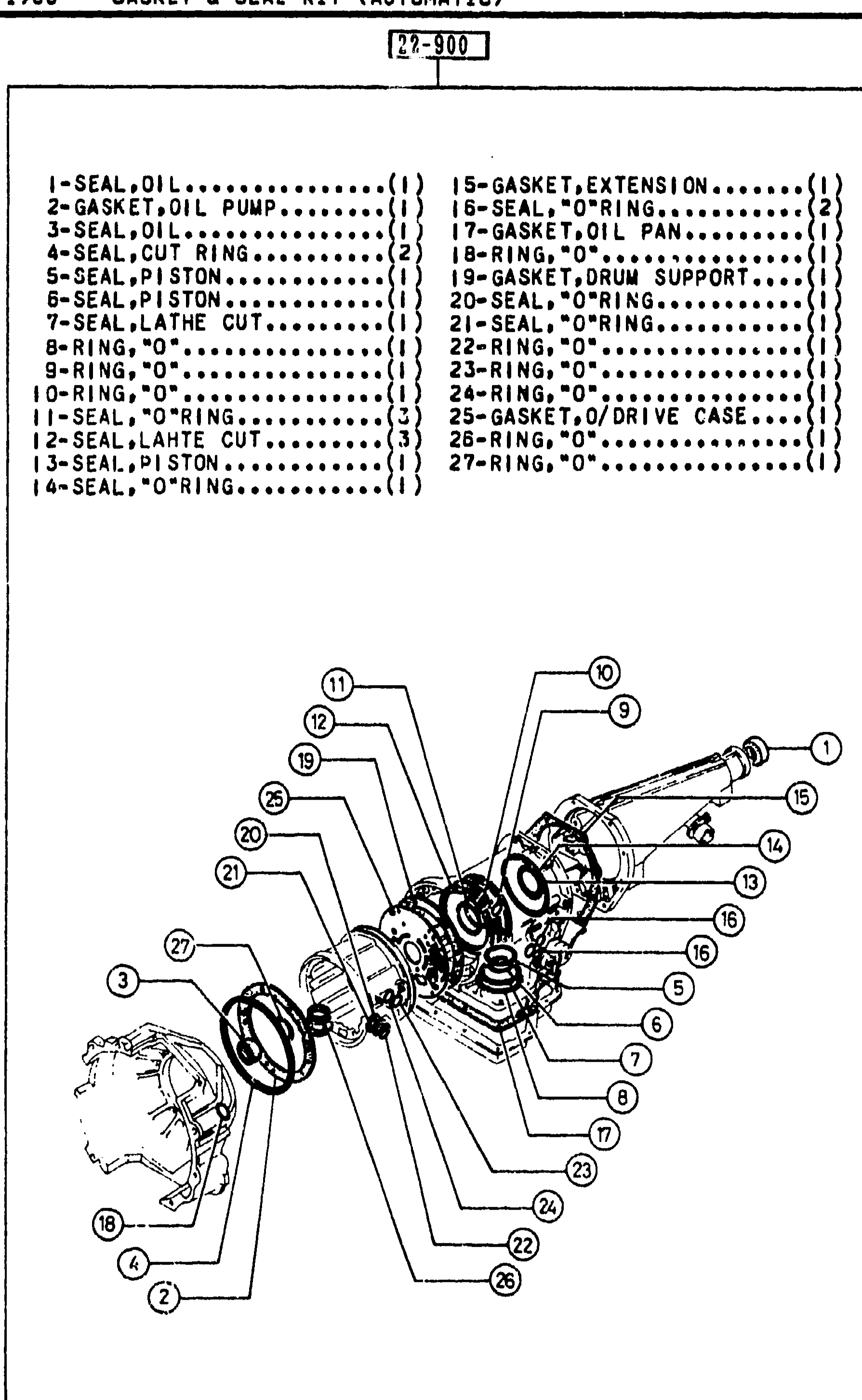
1960 GASKET & SEAL KIT (AUTOMATIC)
1-I 9Exploded view of the automatic-transmission gasket & seal kit (kit number 22-900). The numbered legend at the top lists 27 kit contents. The diagram shows the entire transmission case + extension housing + oil pump cover, with numbered balloon callouts (1–27) corresponding to the legend. Figure-ref label 'AUNA01' bottom-left.
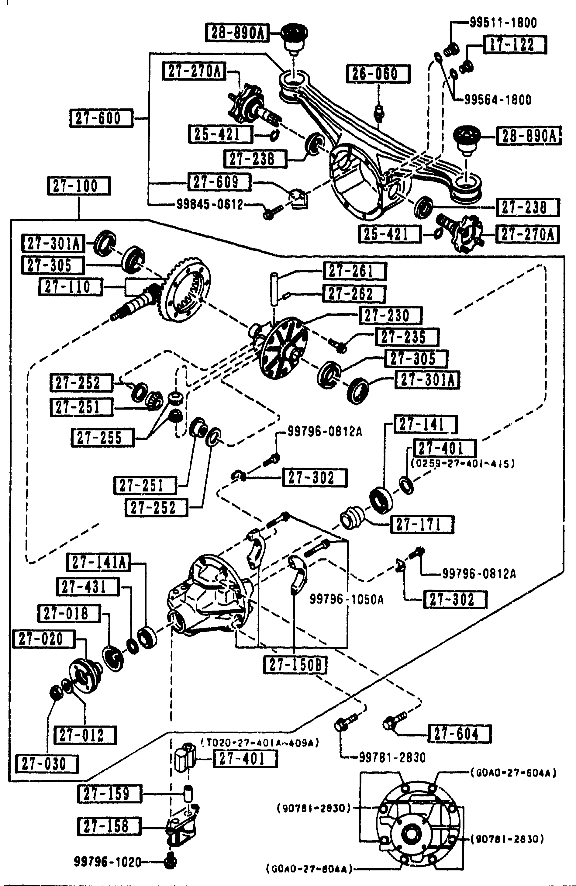
2710 REAR DIFFERENTIALS (NORMAL DIFF.) — continued
1-I11Continuation exploded view of the normal rear-differential assembly (left half of page). Top portion repeats the carrier-housing view with the cover, breather and oil-fill region (17-122, 26-060, 27-100, 27-235, 27-238, 28-890A, 25-421, 27-270A, 27-600, 27-609 etc.). Middle: ring-gear and differential-case section (27-110 ring/pinion, 27-230 case, 27-235 bolt, ring gear, 27-251/27-252/27-261/27-301A side-gear washers and shims). Lower: pinion-shaft and bearing assembly with 27-141, 27-141A, 27-150B, 27-018, 27-020, 27-012, 27-030, 27-158, 27-159, 27-431, hardware 99796-08124, 99796-1050A, 99781-2830, etc.
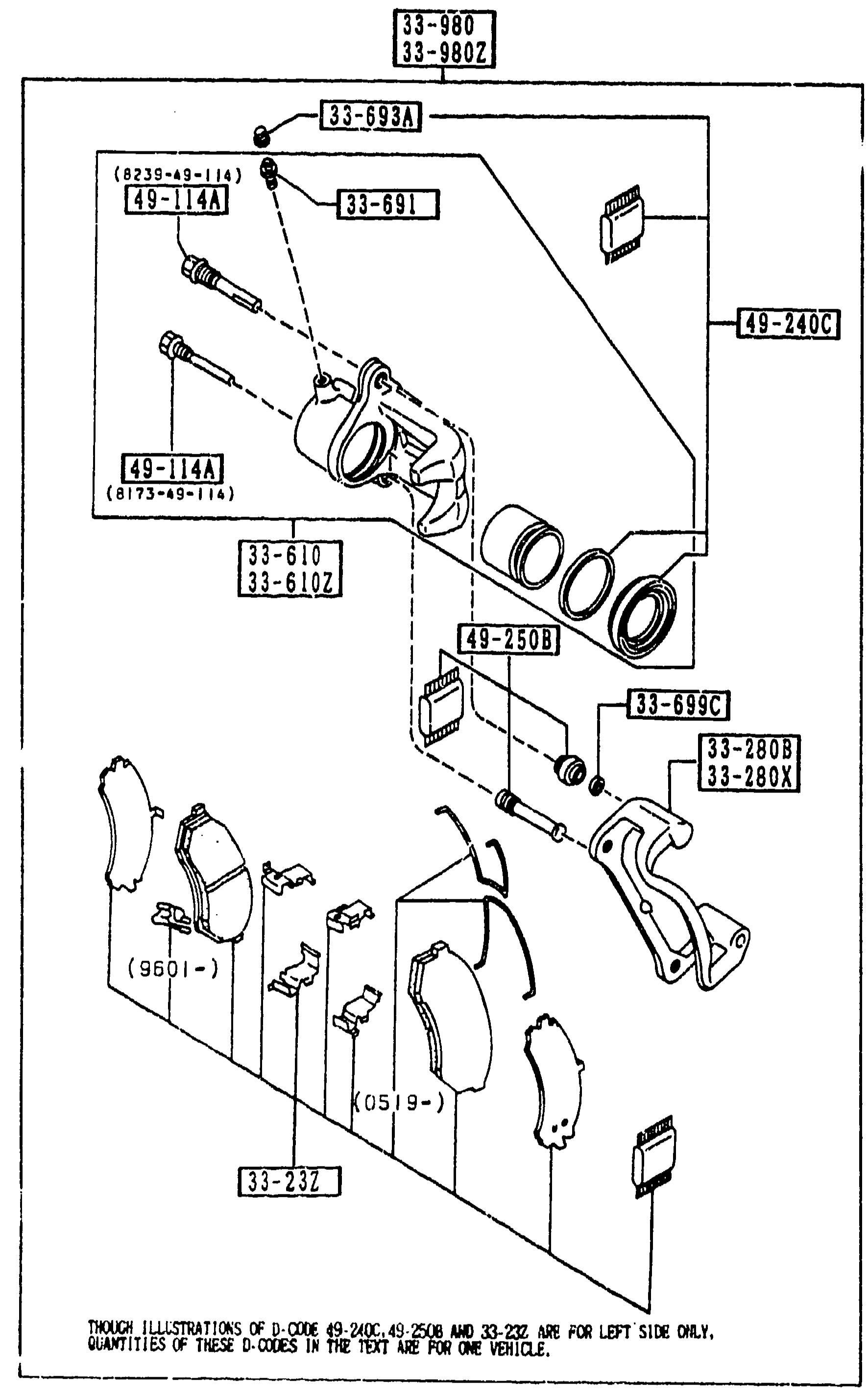
FRONT BRAKE MECHANISMS
1-I13Exploded view of the front brake caliper assembly. Shows caliper body with two pistons (R/L variants 33-610 / 33-610Z), mounting support brackets (33-280B / 33-280X), brake pads (pad set 33-23Z, with 9601- and 0519- production variants), slider pins 49-114A (8235-49-114), pin bolts 49-240C, bleeder screw 33-691 and cap 33-693A, lock pin 33-699C, dust boots / piston seals 49-250B, and the caliper assemblies 33-980 / 33-980Z. Tool callouts 49-114A, 49-240C, 49-250B are visible on the left.
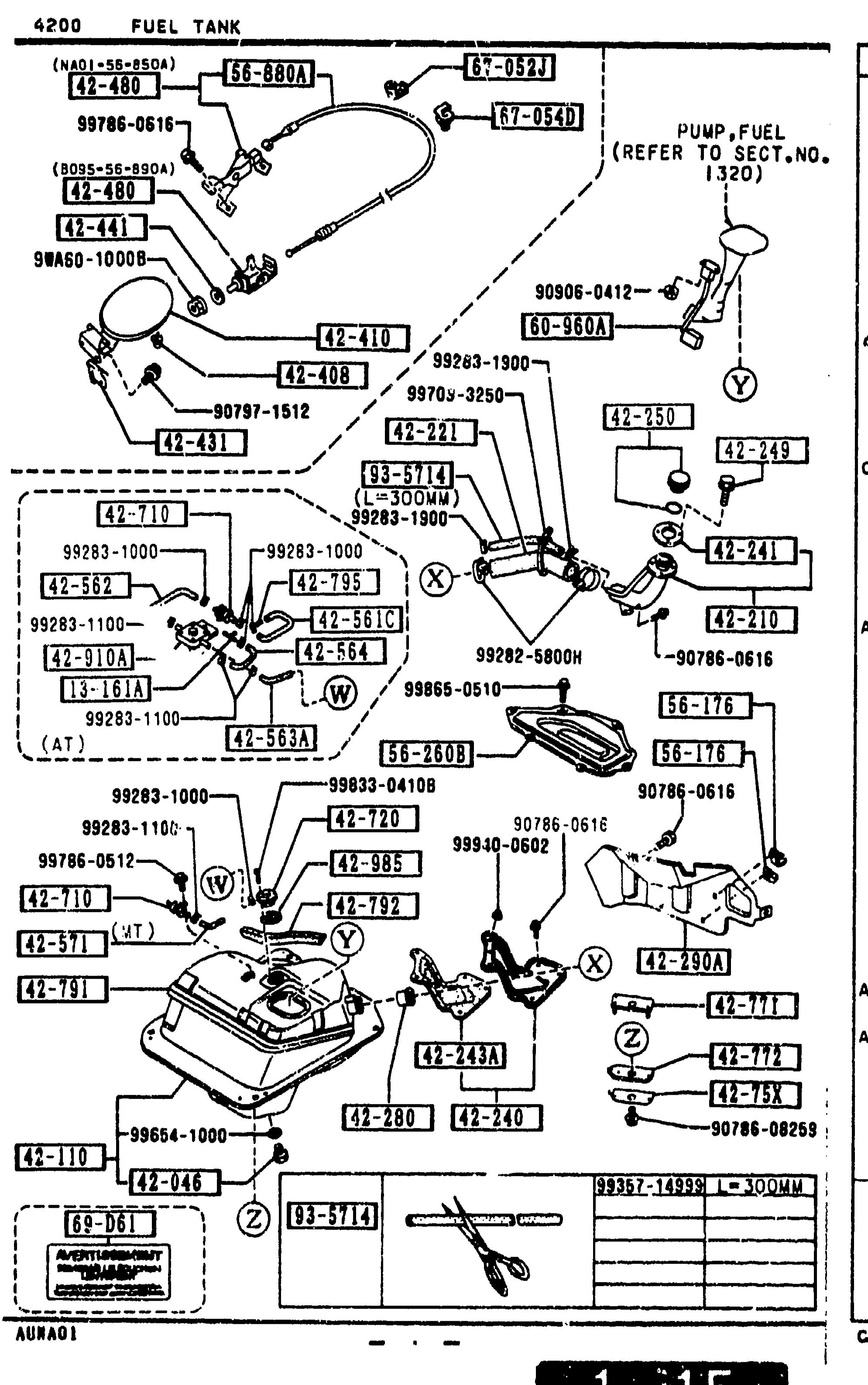
4200 FUEL TANK
1-I15Exploded view of the fuel tank assembly showing the tank, filler pipe, hoses, dust covers, gasket, fuel pump (referencing SECT.NO. 1320), filler cap, and assorted clips/clamps. Balloon callouts include 42-480, 65-001/001H, 42-046, BC68-42-045, 42-410, 42-110, 42-210, 42-210A, 42-300W, 42-240, 42-238, 42-364B, 42-244, 42-345A, 42-540, 42-490, 42-561, 42-562, 42-563A, 42-564, 42-571, 65-001H, etc. Bottom-left identification plate shown with the catalog code AUNA01.
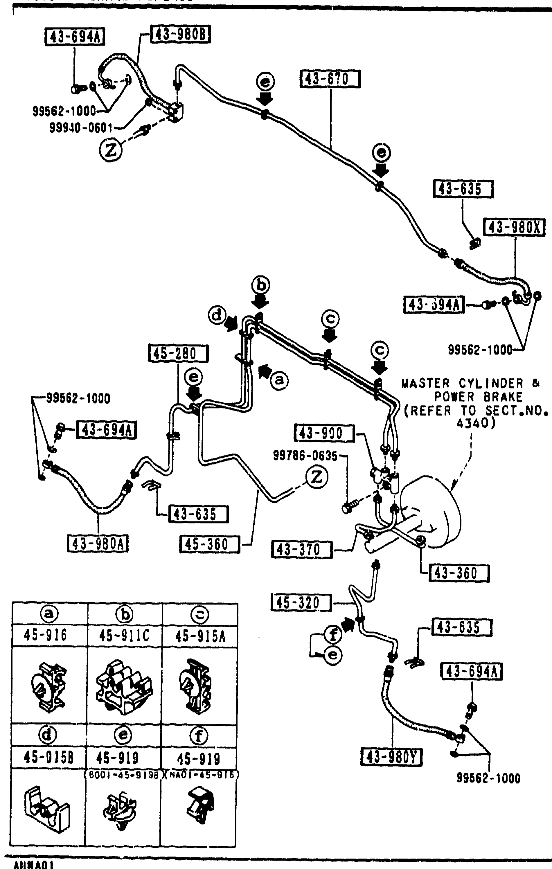
BRAKE PIPINGS
1-I16Sheet 2 of the brake pipings exploded view. Same underbody routing layout as the previous page reprinted on the left to key the additional pipe-holder/clip rows (45-915A, 45-915B, 45-916, 45-919) and new pipe references (43-394A, 43-920). Lower-left inset shows the six clip-shape variants (a-f).
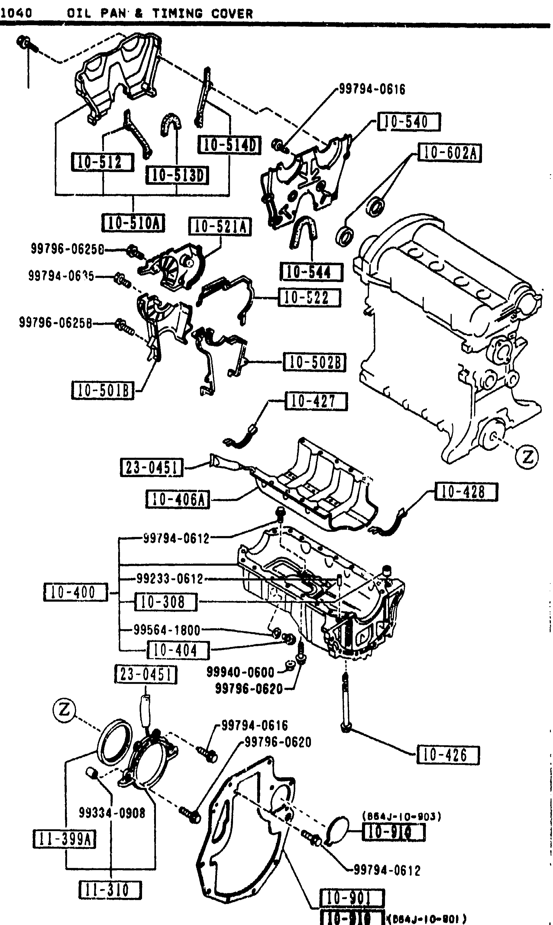
1040 OIL PAN & TIMING COVER
1-I3Exploded view of the B6 oil pan and timing-cover assembly. Top half shows the timing-belt upper cover (10-501B), lower cover (10-510, 10-512, 10-513D, 10-514D, 10-516A), inner-belt cover (10-513), gaskets (10-501B, 10-502B, 10-516A) and miscellaneous mounting bolts (99794-0616, 99796-0625D, 99796-0625B). Bottom half shows the oil pan (10-400), oil-pan gasket (10-427/10-428), pickup tube (10-426), drain plug (10-404) with washer (99564-1800), oil baffle plate (10-406A), and the timing-cover lower seal and front crank seal arrangement (10-91D, 11-310, 11-399A).
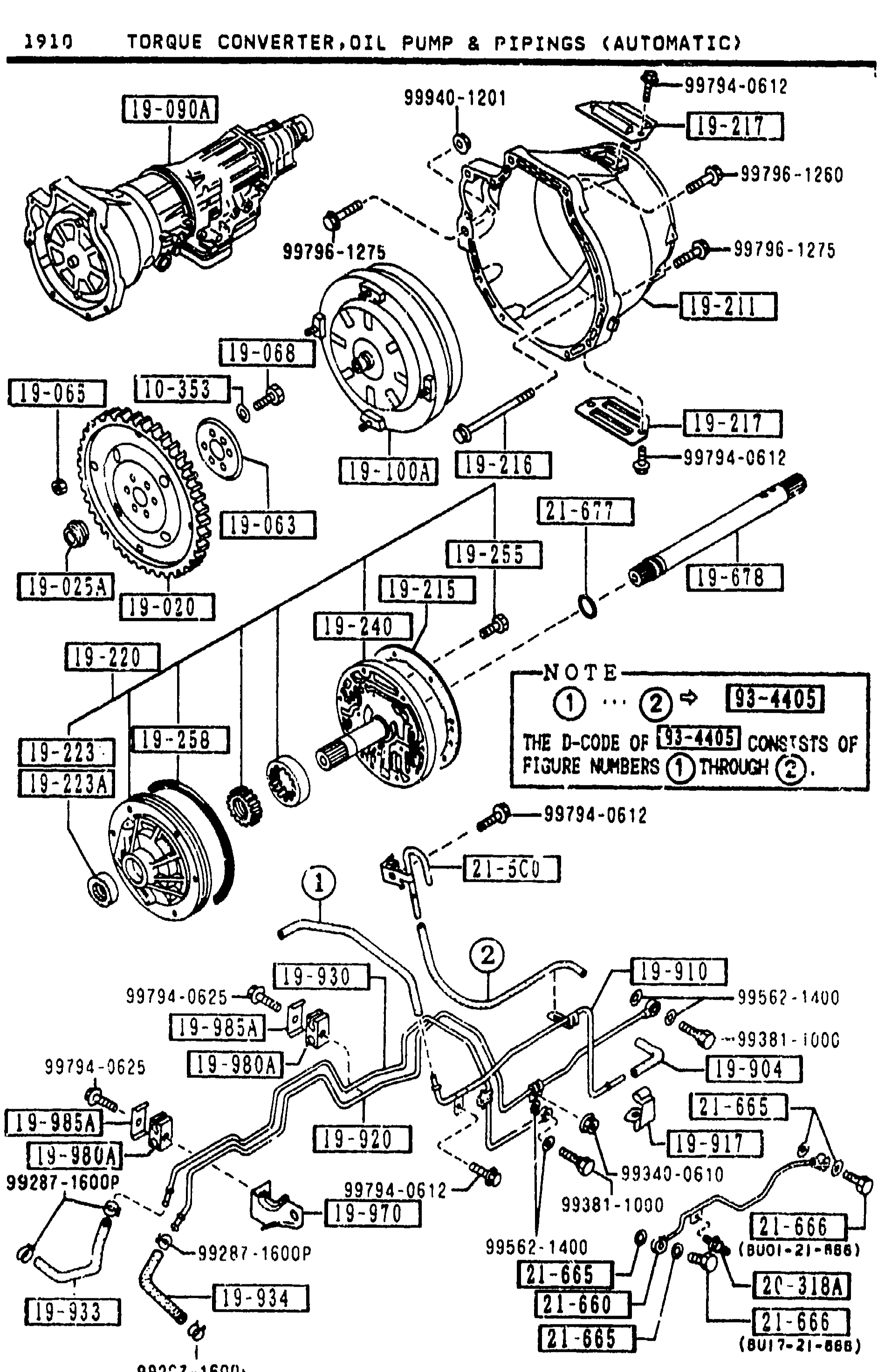
1910 TORQUE CONVERTER, OIL PUMP & PIPINGS (AUTOMATIC)
1-J 7Continuation of the exploded view of the automatic transmission torque converter, oil pump & pipings assembly. Same overall illustration as the previous page (1-i 7) with balloon callouts indexing additional parts: bracket, oil-pipe support, oil-pipe clip, bolts, breather, governor tube, seal washer, connector bolt, O-ring and a hose. The central NOTE balloon repeats: 'THE D-CODE OF [19-465] CONSISTS OF FIGURE NUMBERS [1] THROUGH [7]'.
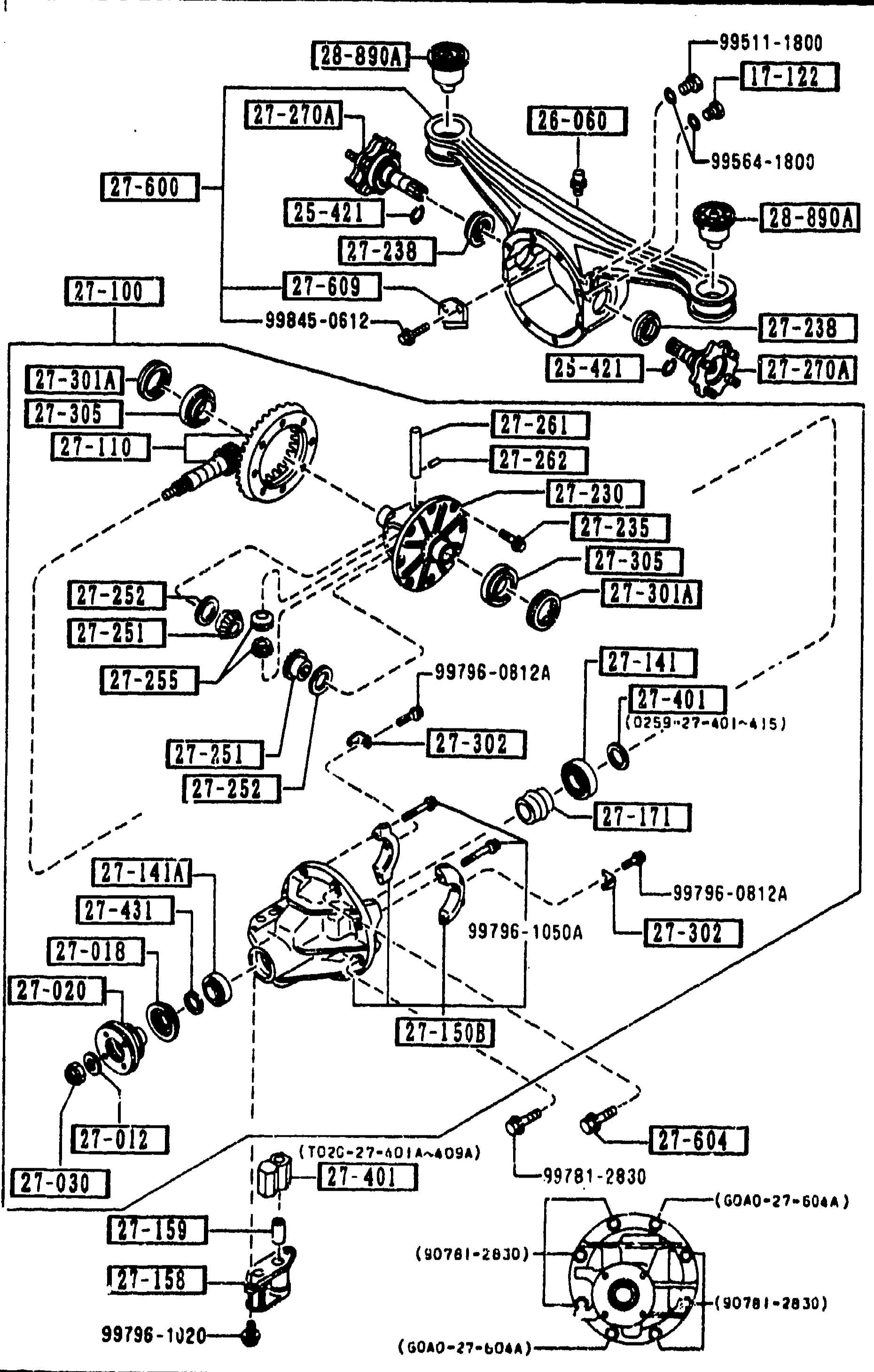
2710 REAR DIFFERENTIALS (NORMAL DIFF.) — continued
1-J11Continuation exploded view of the normal rear-differential assembly (same artwork as previous pages, left half). Listed here: 27-262 pin, 27-270A shaft output, 27-301A screw adjust, 27-302 plate lock, 27-305 bearing, 27-401 spacer (multiple thickness variants from T=3.08MM through T=3.47MM, length 50.850).
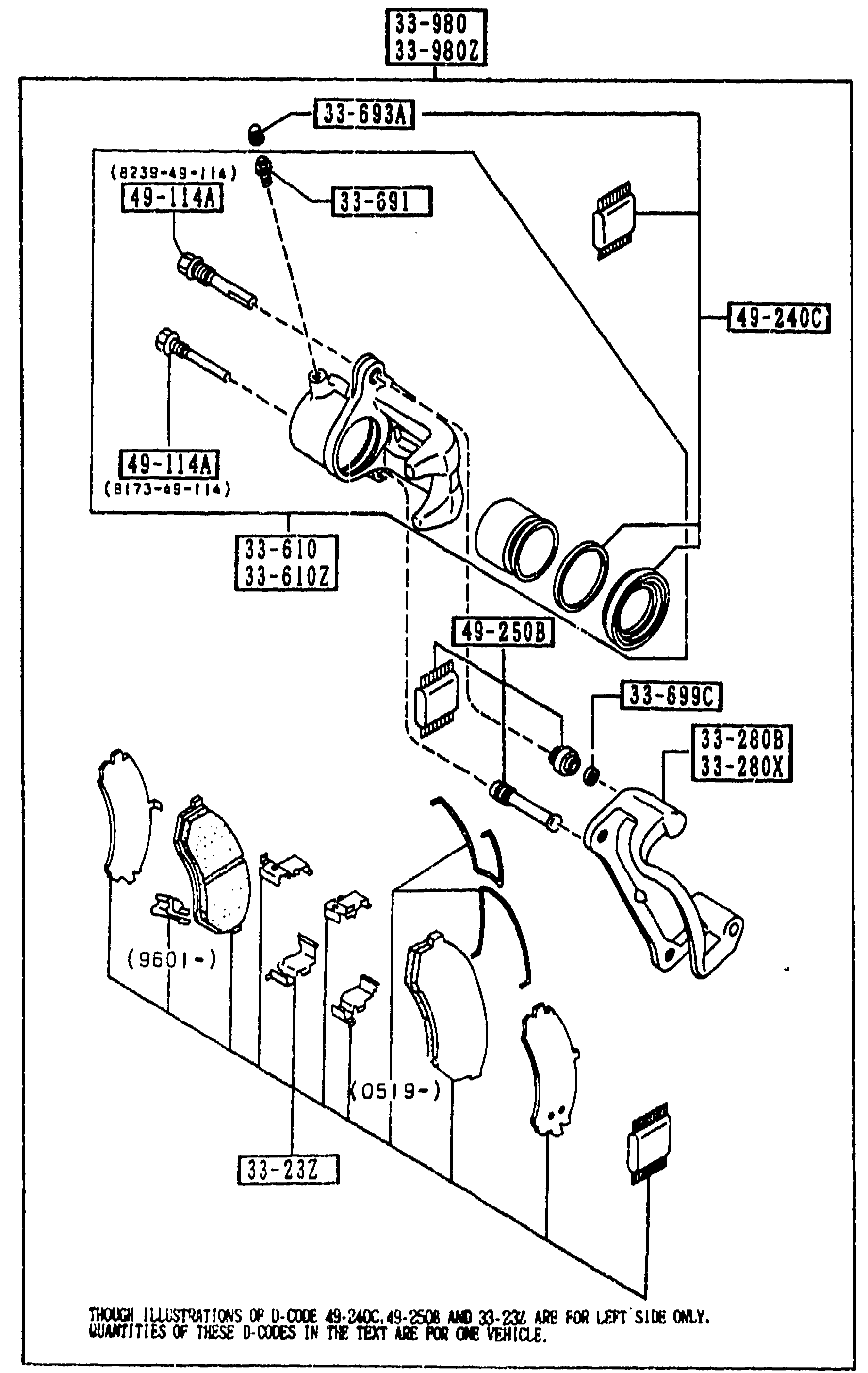
FRONT BRAKE MECHANISMS
1-J13Exploded view of the front brake caliper (same caliper assembly as page 1-I13) with focus on the seal kit and boot kit. Shows caliper body 33-610/33-610Z, slider pins 49-114A, pin bolt 49-240C, bleeder screw 33-691 and cap 33-693A, lock pin 33-699C, pad set 33-23Z with date code variants (9601-) and (0519-), mounting support brackets 33-280B/33-280X, and caliper assembly 33-980/33-980Z. Boot/seal kit 49-250B callout near piston.
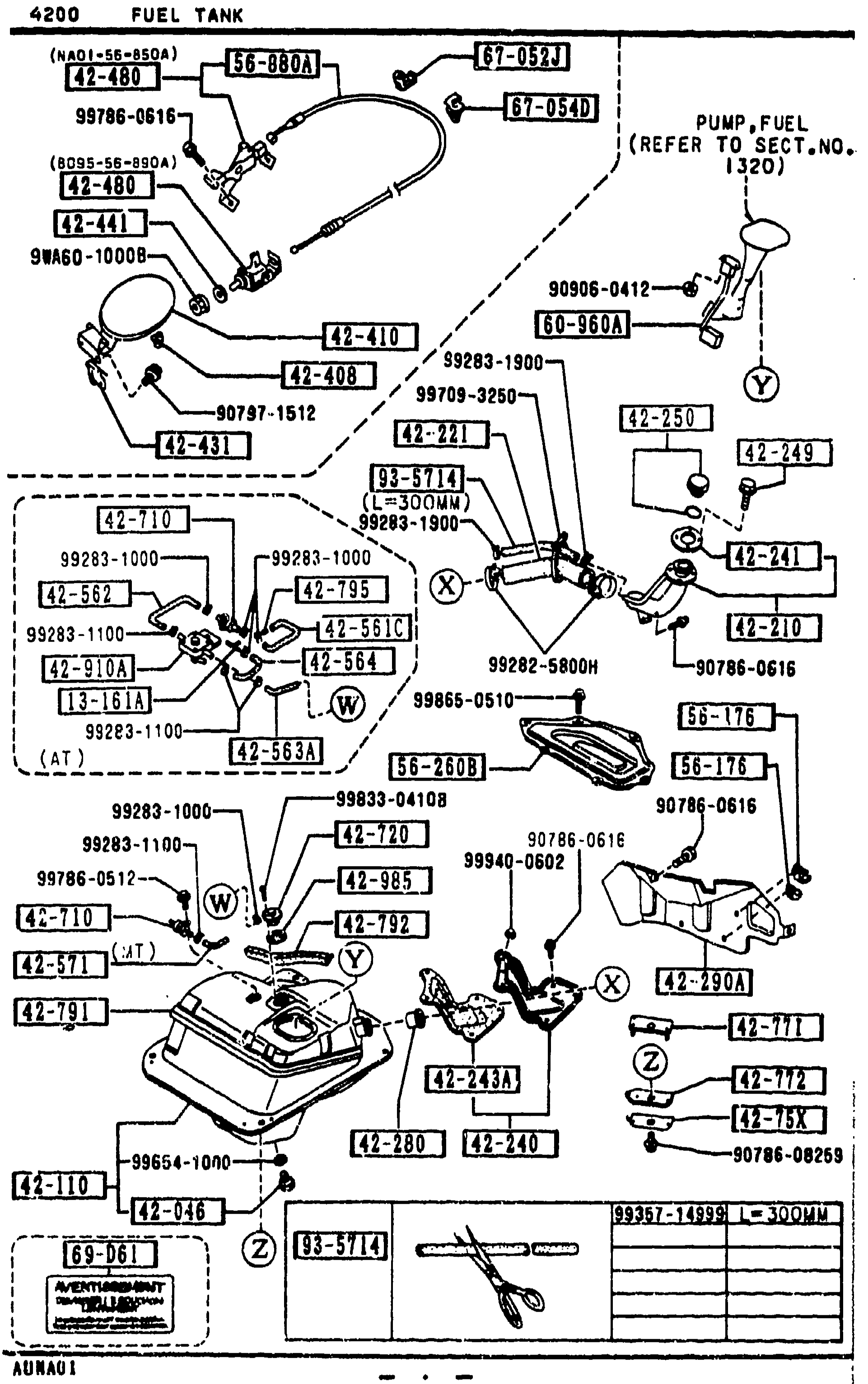
4200 FUEL TANK
1-J15Continued exploded view of the fuel tank assembly: filler pipe, hoses, dust covers, breather hoses, vent hose, filler cap, and pump assembly. Balloon callouts include 42-480, 65-001/001H, 42-046, BC68-42-045, 42-410, 42-110, 42-210, 42-210A, 42-300W, 42-240, 42-238, 42-364B, 42-244, 42-345A, 42-490, 42-540, 42-561, 42-562, 42-563A, 42-564, 42-571. Bottom-left identification plate shown with the catalog code AUNA01. Page footer reads 1-J15.
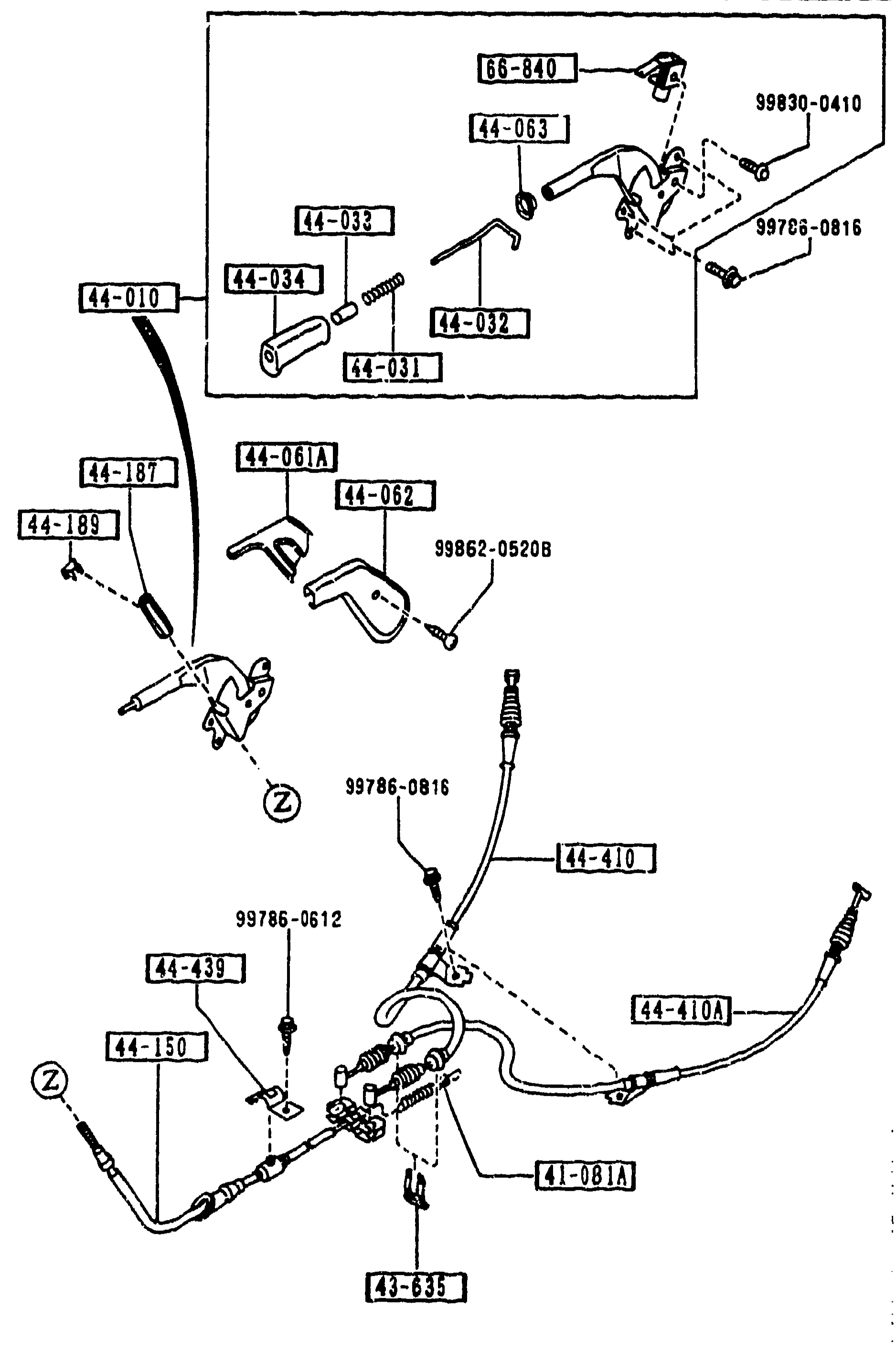
PARKING BRAKE SYSTEM
1-J16Exploded view of the parking brake system. Top half shows the parking-brake lever assembly (handle, release button, return spring, cover, cap) with its mounting hardware. Bottom half shows the parking-brake cables (front cable assembly with adjuster, rear cable assemblies left and right) connected to the equalizer with circle (Z) reference flags indicating cable continuity to off-page sections.
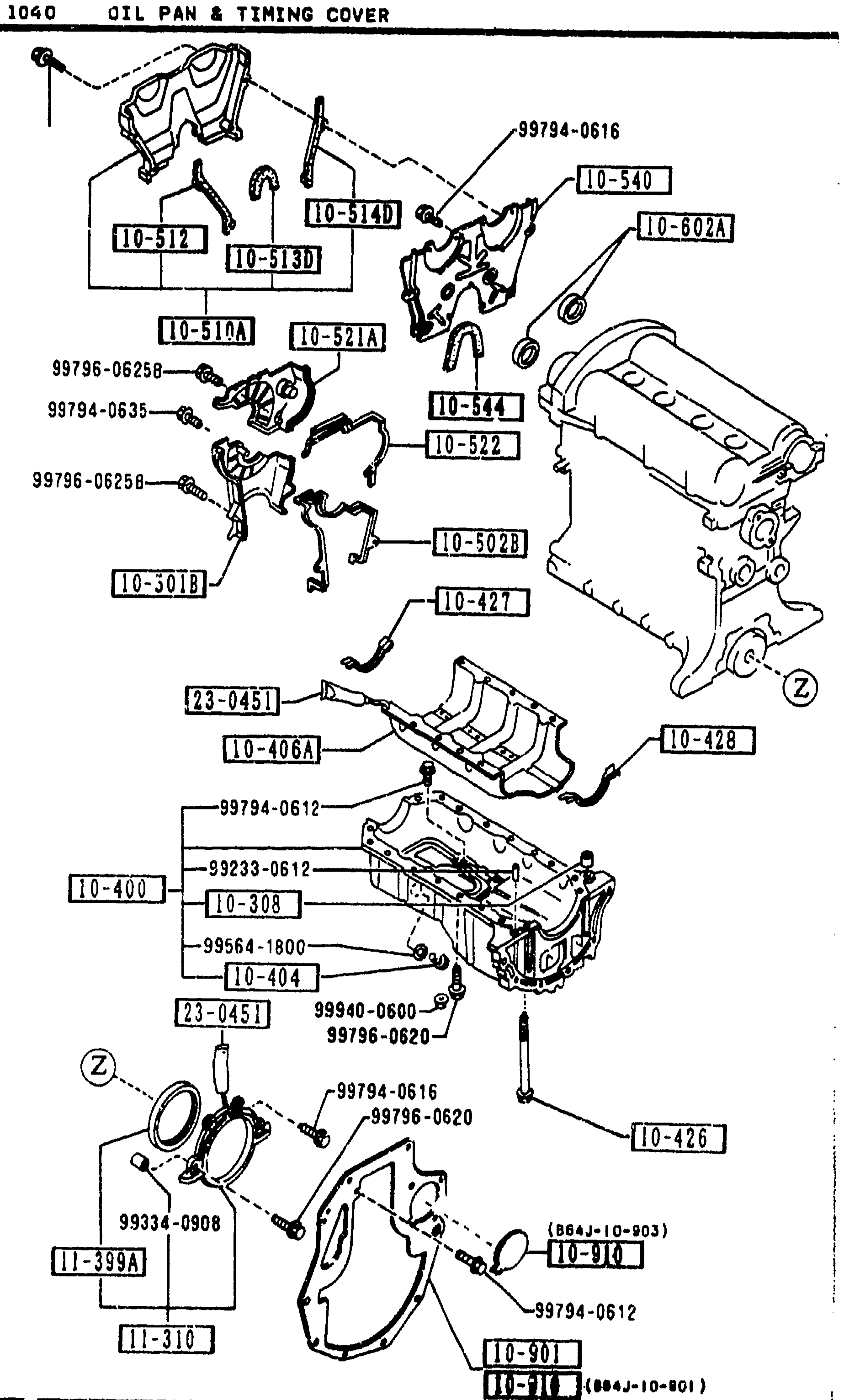
1040 -2 M OIL PAN & TIMING COVER
1-J3Continuation exploded view of the oil pan & timing cover assembly (same drawing as previous page). Timing-cover variants (10-512, 10-513D, 10-514D, 10-521A, 10-522, 10-540, 10-544, 10-602A), end plate (10-301B, 10-901, 10-910), rear cover (11-310, 11-399A), oil seal-crankshaft (11-312), silicon tube (23-0451). Lower-half oil-pan view shows 10-400 pan, 10-308 pin, 10-404 plug, 10-426 baffle, drain washer (99564-1800), and front crank-seal carrier 11-399A.
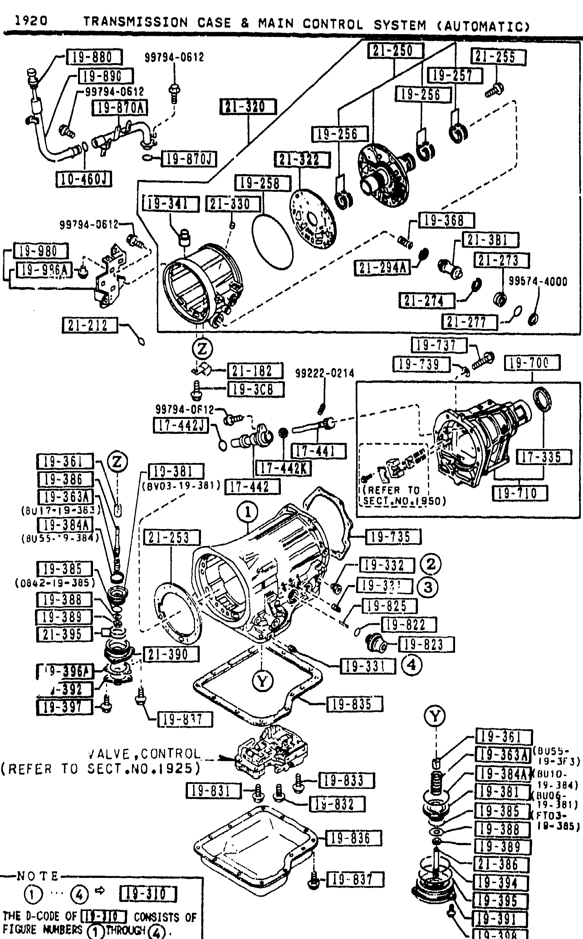
1920 TRANSMISSION CASE & MAIN CONTROL SYSTEM (AUTOMATIC)
1-K 7Exploded view of the automatic transmission case and main control system. Top portion shows the rear extension housing with output shaft, speedometer driven gear, seals and O-rings (balloons 1-7). Middle section shows the case-T-mission assembly with bolts, plates and the cut ring (balloons 8-12). Bottom section shows the valve body and oil pan with anchor bolts and plug, with a reference 'VALVE,CONTROL (REFER TO SECT.NO.1925)'. A NOTE balloon repeats: 'THE D-CODE OF [19-405] CONSISTS OF FIGURE NUMBERS [1] THROUGH [7]'.
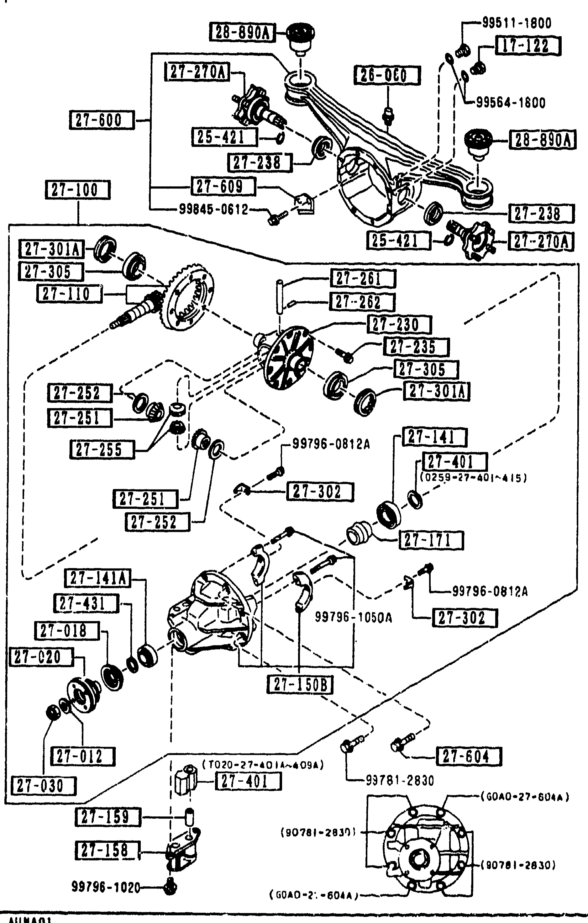
2710 REAR DIFFERENTIALS (NORMAL DIFF.)
1-K11Exploded view of the rear differential (normal/open differential type). Shows the differential carrier housing with the ring gear, pinion gear, drive pinion shaft, side bearings, pinion shim spacers (27-401 thru 27-407), differential case, side gears, pinion mate gears, cross shaft, baffle plate, and the rubber sub-frame mounts. Numerous balloon callouts identify components (28-890A, 27-270A, 25-421, 21-060, 99511-1800, 17-122, 28-890A, 27-238, 99554-1800, 28-890A, 27-600, 27-600A, 27-100, 27-238, 99845-0812, 25-421, 27-301A, 27-305, 27-110, 27-261, 27-282, 27-281, 27-230, 27-305, 27-301A, 27-252, 27-251, 27-255, 27-141, 27-401, 27-251, 27-302, 27-141A, 99796-0812A, 27-401, 27-431, 27-604, 27-018, 27-609, 27-020, 28-890A, 27-159, 27-158, 27-401, 99796-1020, 99796-0812A, 27-302, 27-012, 27-030, 27-604, 99781-2830, 60A0-27-604A, 90781-2830). Bottom of figure shows pinion-shim measurement note ranges keyed to dimensions L=50.875 through L=51.050.
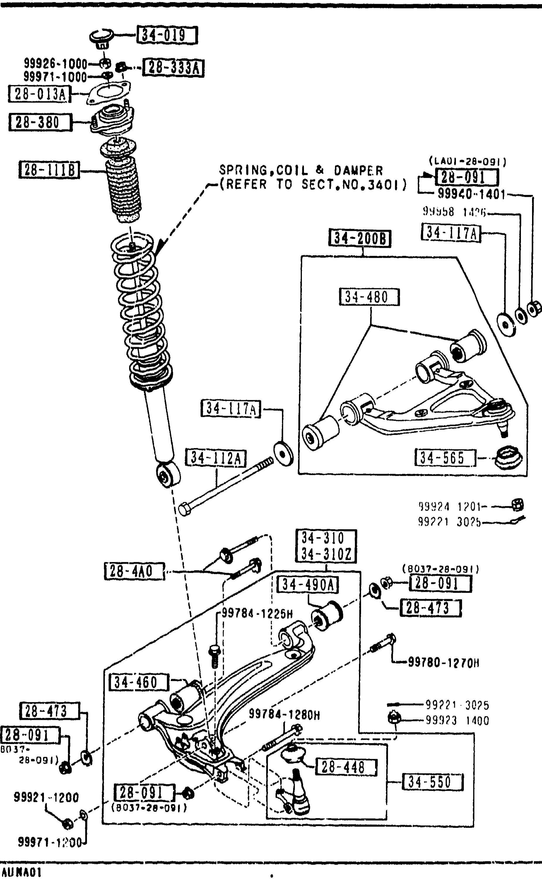
FRONT SUSPENSION MECHANISMS
1-K13Exploded view of the front suspension assembly. Shows coil-spring-over-damper strut (28-1118 SPRING, COIL & DAMPER, refer to section No. 3401), upper damper top hat with rubber mount 28-380 and seat 28-013A, locknuts 99926-1000/99971-1000, upper control arm 34-200B with bushings 34-117A and ball joint 34-480, lower control arm 34-460 with bushings 34-310/34-310Z, ball joint 34-550, anti-roll bar end link, and various fasteners (28-091, 99784-1225H, 99780-1270H, 99784-1280H, etc.).
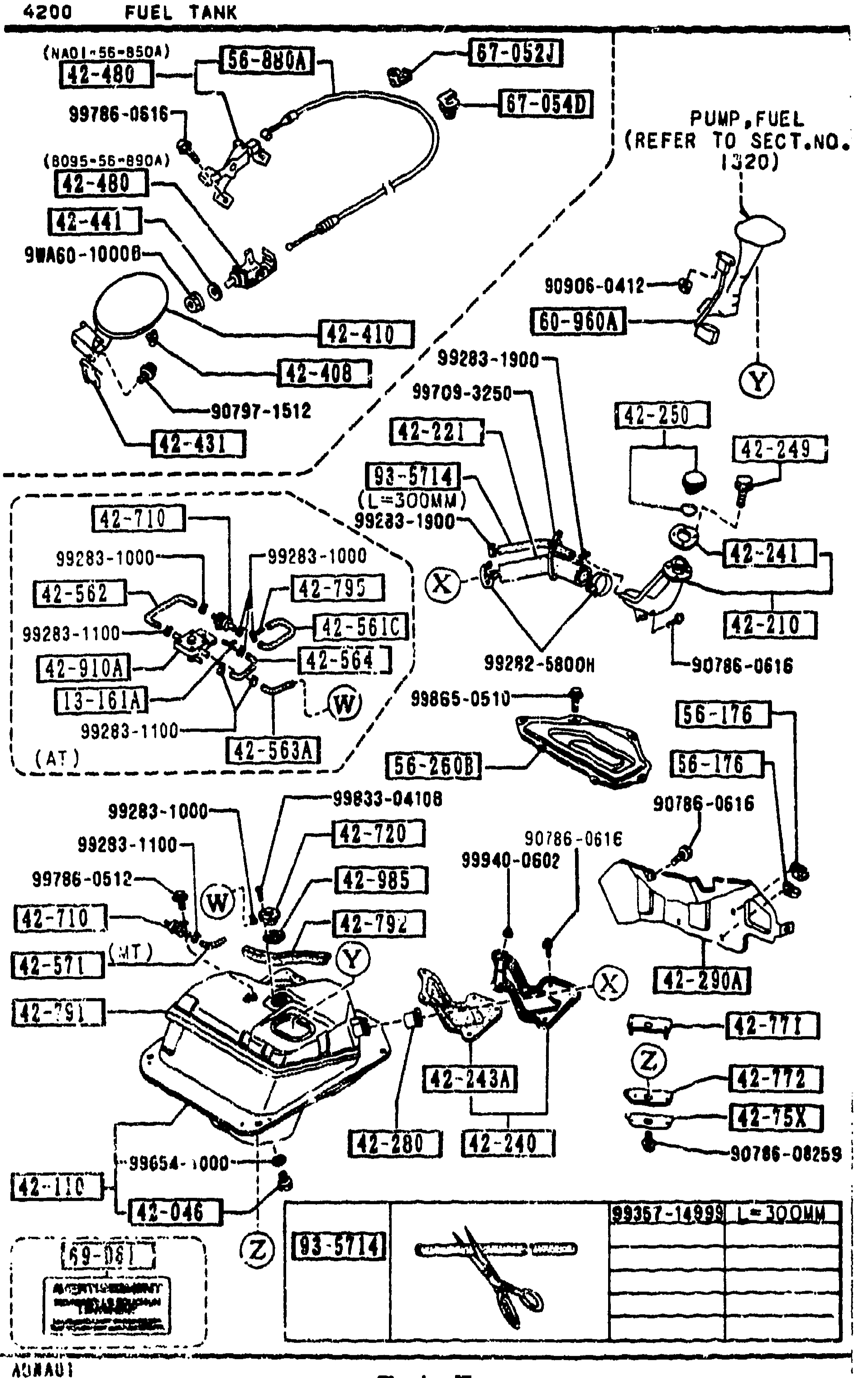
4200 FUEL TANK
1-K15Continued exploded view of the fuel tank assembly (page 4200-3) showing the tank with check valve, fuel vapor valve, fuel tank reinforcement, upper/lower mount rubbers, fuel tank pads, insert, vapor valve, jack handle holder, fuel gauge cover, fuel-lid opener cable, and fuel gauge. Balloon callouts include 42-710, 42-720, 42-78X, 42-77X, 42-771, 42-772, 42-743, 42-742, 42-745, 42-785, 42-985, 56-176, 56-260B, 56-880A, 60-960A.
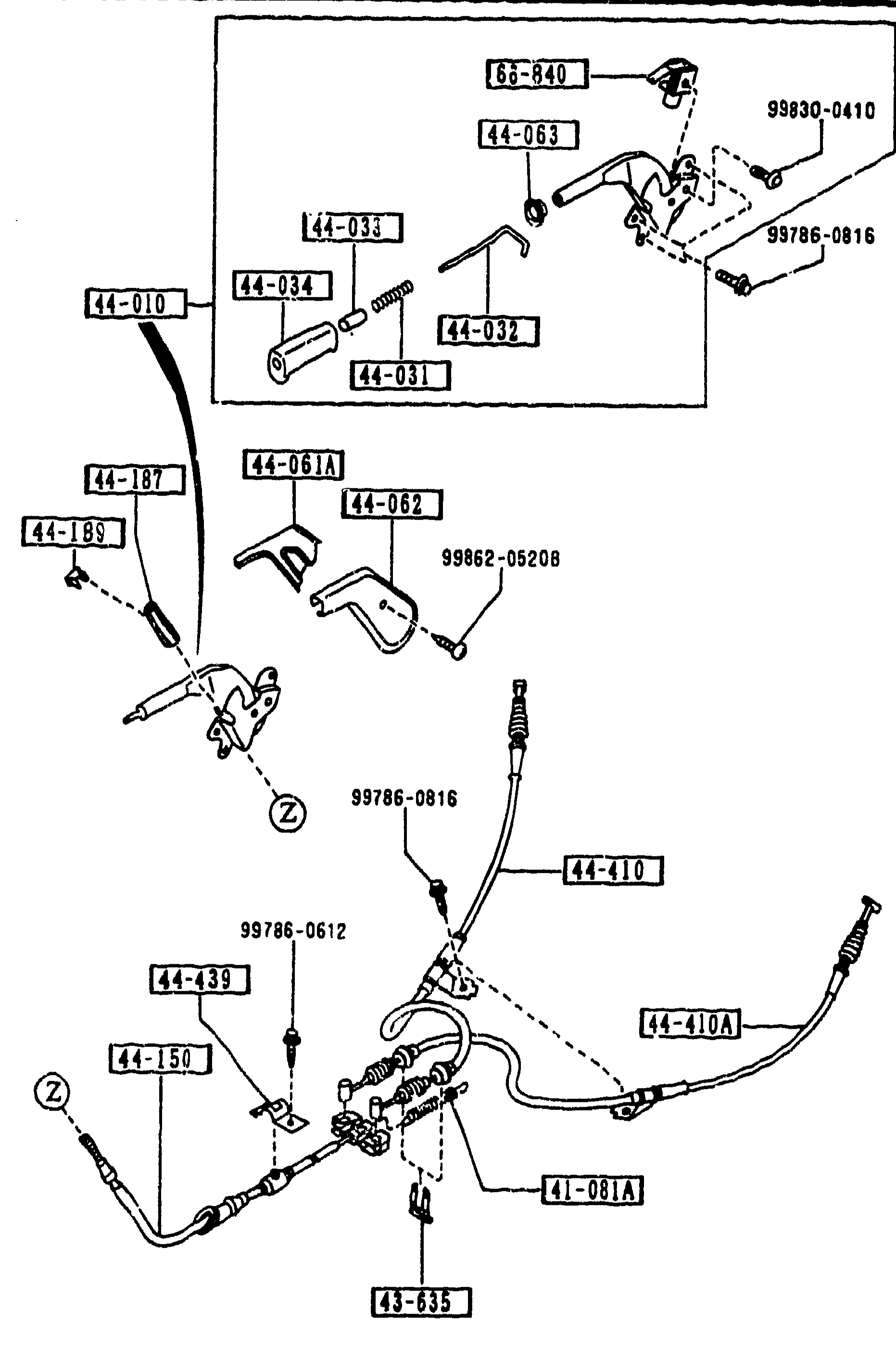
PARKING BRAKE SYSTEM
1-K16Sheet 2 of the parking brake system exploded view. Same lever-and-cable arrangement reprinted from the previous sheet, used to key the additional rows for the L.H. rear parking cable (44-410A), cable clip (44-439) and parking-lamp switch (66-840). Upper inset shows the lever head detail (handle, release rod, button, cap, return spring) and the parking-lamp switch position above the lever.
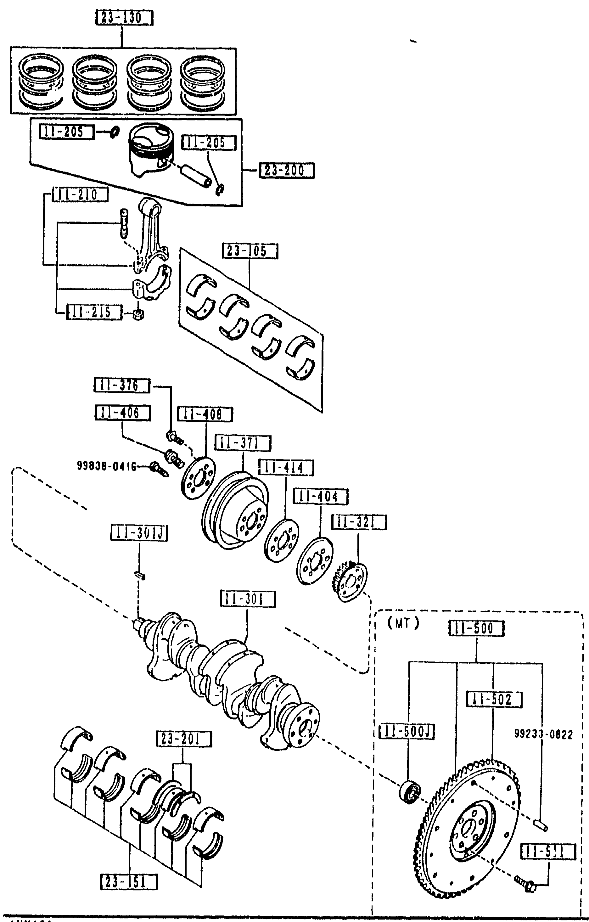
1100 PISTON, CRANKSHAFT & FLYWHEEL
1-K3Exploded view of B6 piston, crankshaft and flywheel assembly. Top: piston-ring set (23-130) and the piston (23-200) with wrist pin (11-210) and clip (11-205). Middle: connecting rod (11-210), connecting-rod nuts (11-215), big-end bearings (23-05). Lower left: crank-pulley (11-321) with bolt (11-376), woodruff key (11-301J), oil-pump drive sprocket (11-301), and timing-belt pulley (11-371). Lower right: flywheel (11-500), pilot bearing/wheel (11-502, 11-407), and MT flywheel mounting bolts (99233-0822). Crankshaft thrust bearings (23-201, 23-151) at bottom.
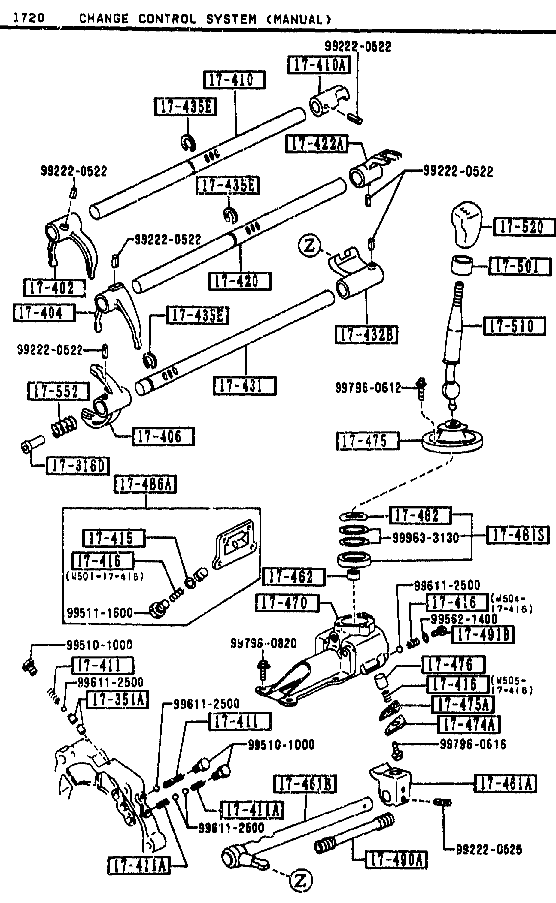
CHANGE CONTROL SYSTEM (MANUAL) — 1720
1-L 6Exploded view of the manual transmission change control system, showing shift forks (17-404, 17-406), shift rods (17-410, 17-420, 17-431), interlock pins (17-432, 17-435A, 17-432B), control end (17-470/17-462), change lever assembly (17-501/17-510/17-520) with knob, and various retaining clips, springs (17-491B, 17-415, 17-416), pins (99222-0522, 99796-0612, 99796-0820, 99796-0616) and bolts (99511-1600, 99510-1000, 99611-2500, 99563-3130, 99562-1400). Two stacked sub-views: upper view shows the shift rod / fork assembly, lower view shows the change-lever housing and control-end linkage.
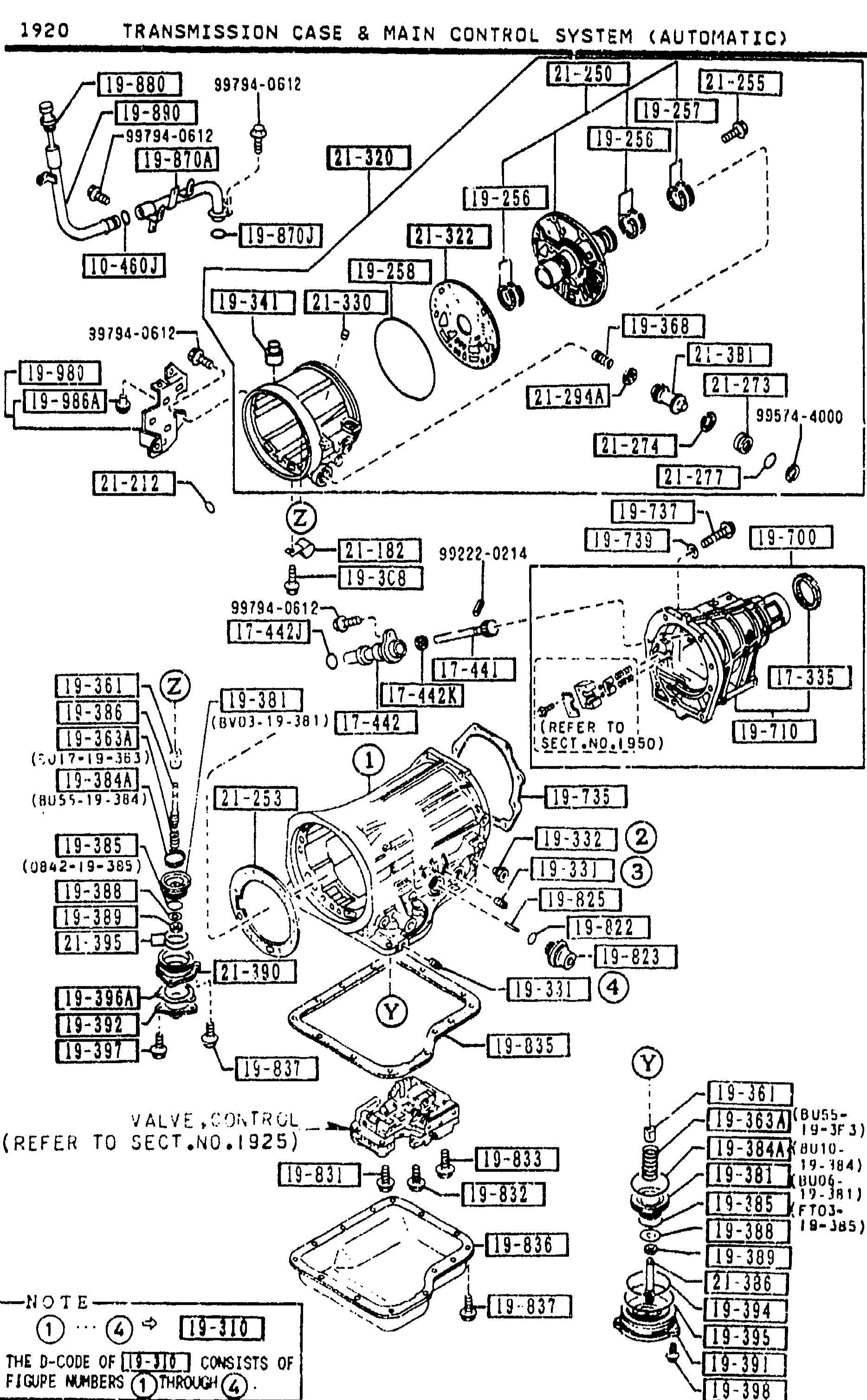
1920 TRANSMISSION CASE & MAIN CONTROL SYSTEM (AUTOMATIC)
1-L 7Continuation of the 1920 Transmission Case & Main Control System exploded view. Same overall illustration carries balloon numbers for the internal servo and piston-stem parts: band strut, piston return spring, cushion spring, band servo piston, piston seal, stem and washers, nut, retainer, cover and lathe-cut seal (balloons 1-12). The 'VALVE,CONTROL (REFER TO SECT.NO.1925)' callout and the central NOTE balloon are repeated.
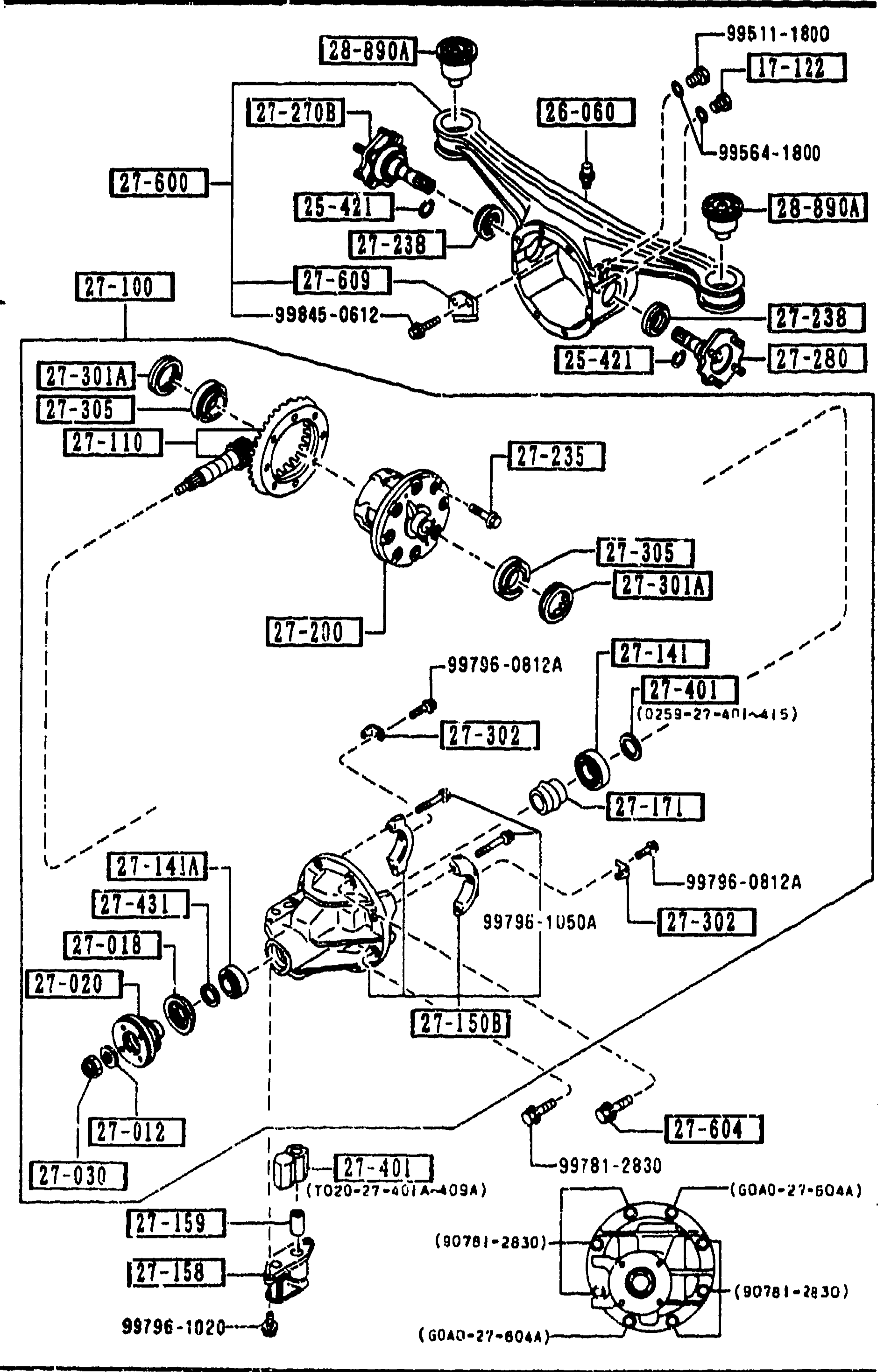
REAR DIFFERENTIALS (LIMITED SLIP DIFF.)
1-L11Exploded view of the rear differential (limited slip type). Shows the differential carrier with pinion flange/companion (27-120A), lock nut (27-130), driving/diff. unit (27-100), gear set (final, R4.300, 27-110), pinion bearings (27-141, 27-141A), oil seal (27-018), companion flange washer (27-012), magnet plug (17-122), breather (26-060), clips (25-421), and various other fasteners and shims. Numbered balloon callouts identify each part.
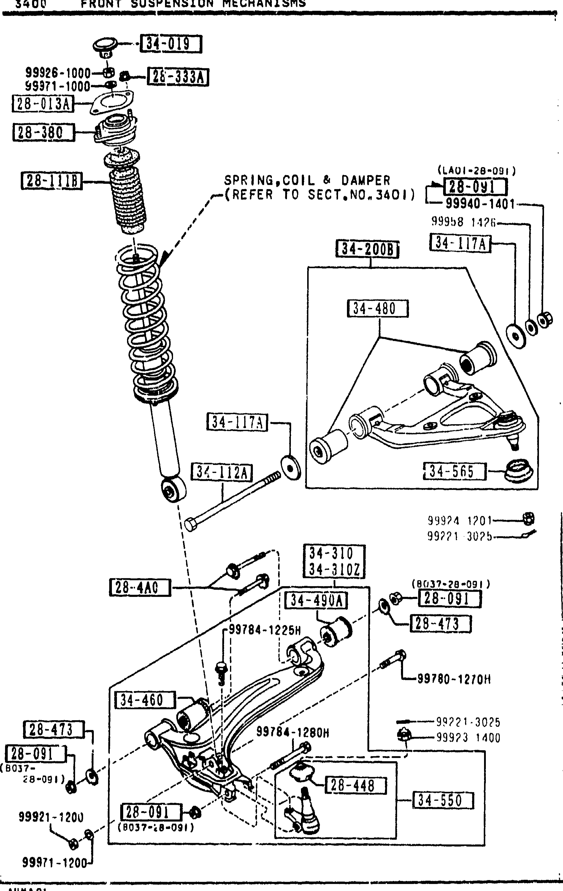
FRONT SUSPENSION MECHANISMS
1-L13Exploded view of the front suspension assembly (same drawing as page 1-K13). Shows strut/spring assembly 28-1118, upper damper hardware, upper control arm 34-200B with bushings 34-480 and ball joint 34-565, lower control arm 34-460 with bushings 34-490A and ball joint 34-550, plus various retaining hardware. Continuation page focusing on the lower-arm subcomponents (bushings, ball joints, dust seals).
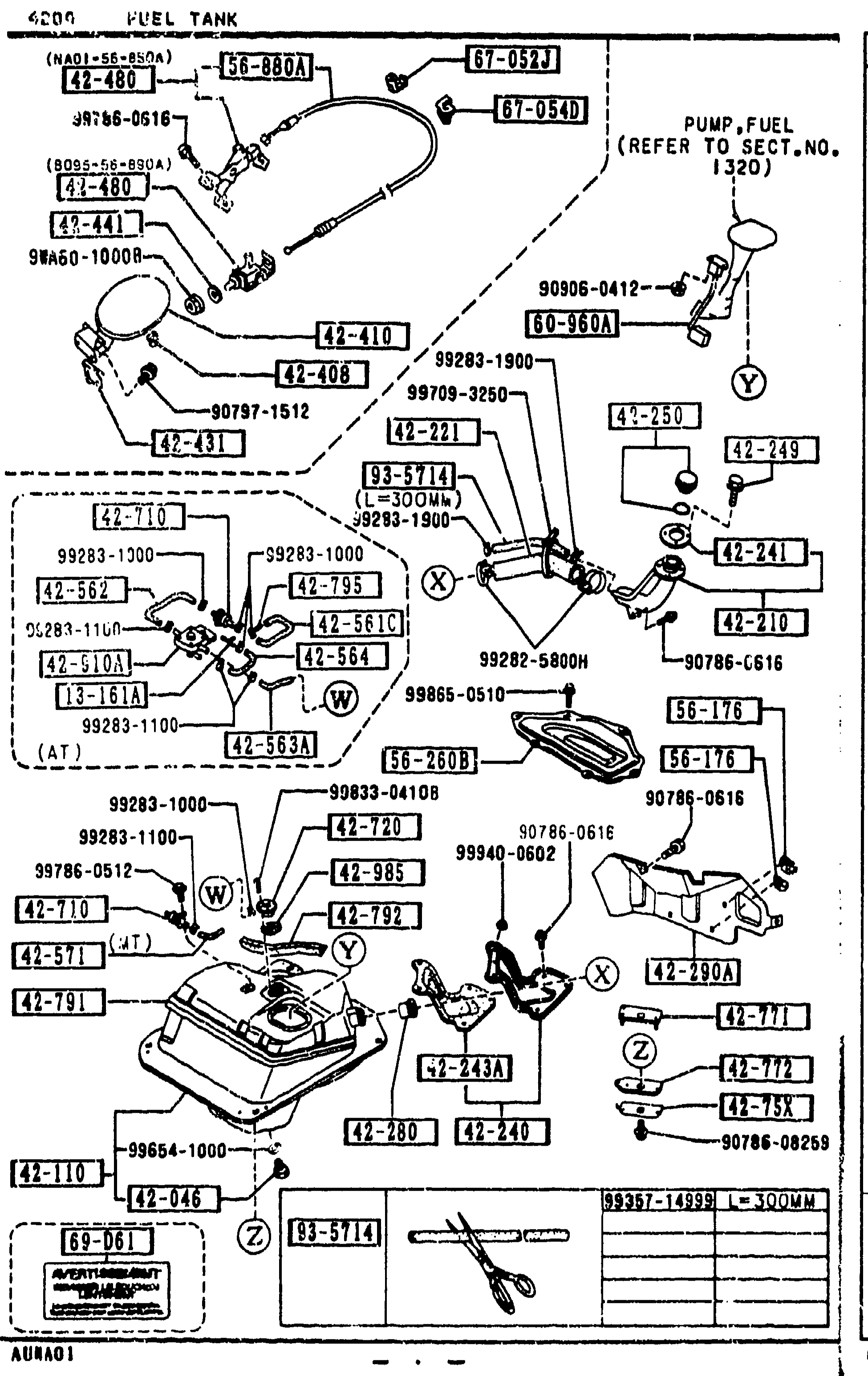
4200 FUEL TANK
1-L15Continued exploded view of the fuel tank assembly (page 4200-4) — repeated overview of the tank, hoses, breather lines, vapor valve, fuel gauge, jack handle holder, and fuel-lid opener cable. Highlighted balloon callouts on this page: 67-052J, 67-054D, 69-D61, 93-5714 (hose). Page footer 1-L15.
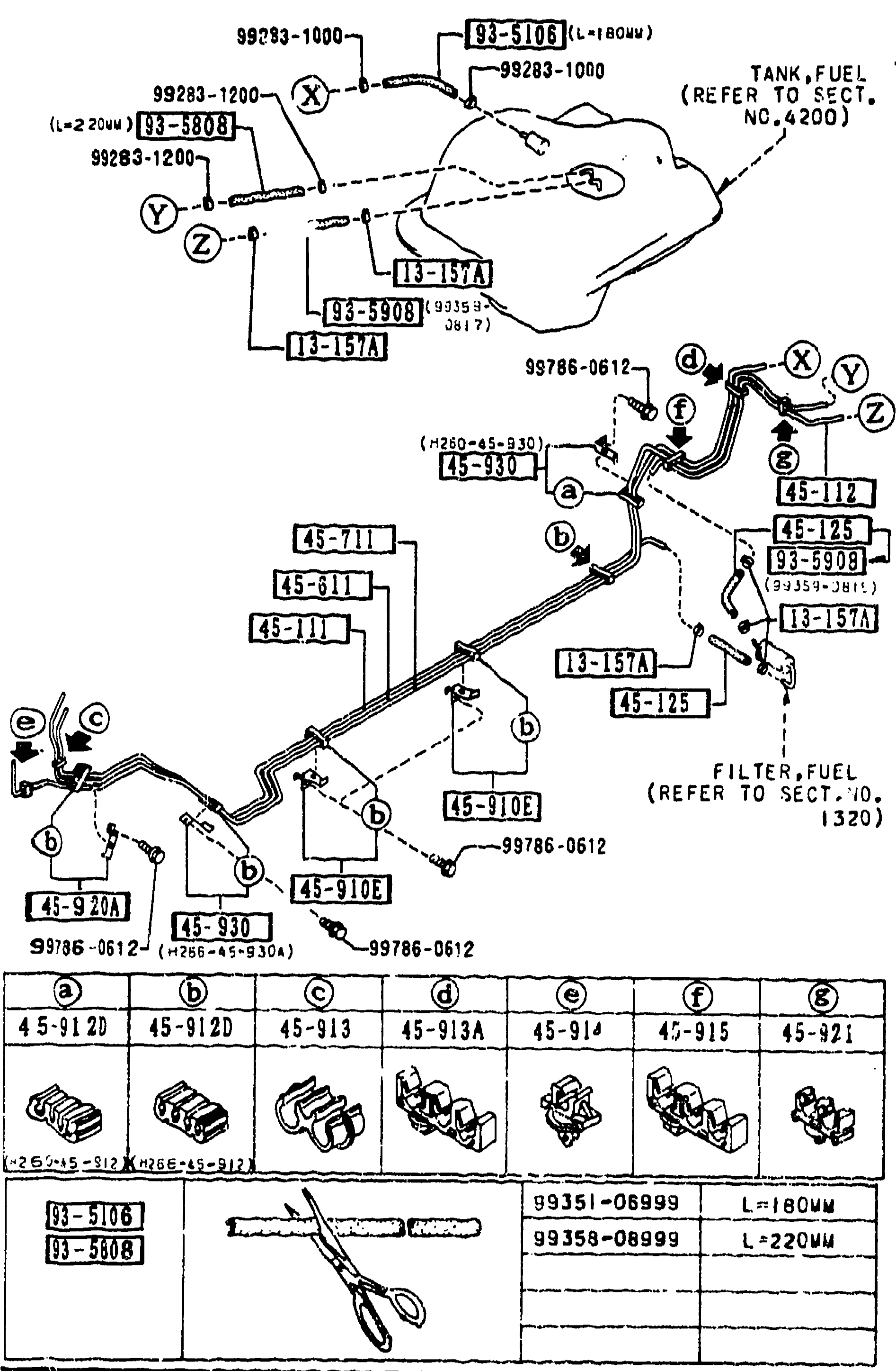
FUEL PIPINGS
1-L16Exploded view of the fuel pipings. Upper section shows the fuel tank (cross-references to SECT. NO. 4200) with feed/return lines and evaporative tubing routed forward through the chassis. Lower-left inset shows the seven pipe-holder/clip shape variants (a-g) labelled 45-912A, 45-912D, 45-913, 45-913A, 45-914, 45-915, 45-921. Below that an additional inset shows two cut-length hose pieces L=180 mm (99351-08999) and L=220 mm (99358-08999).
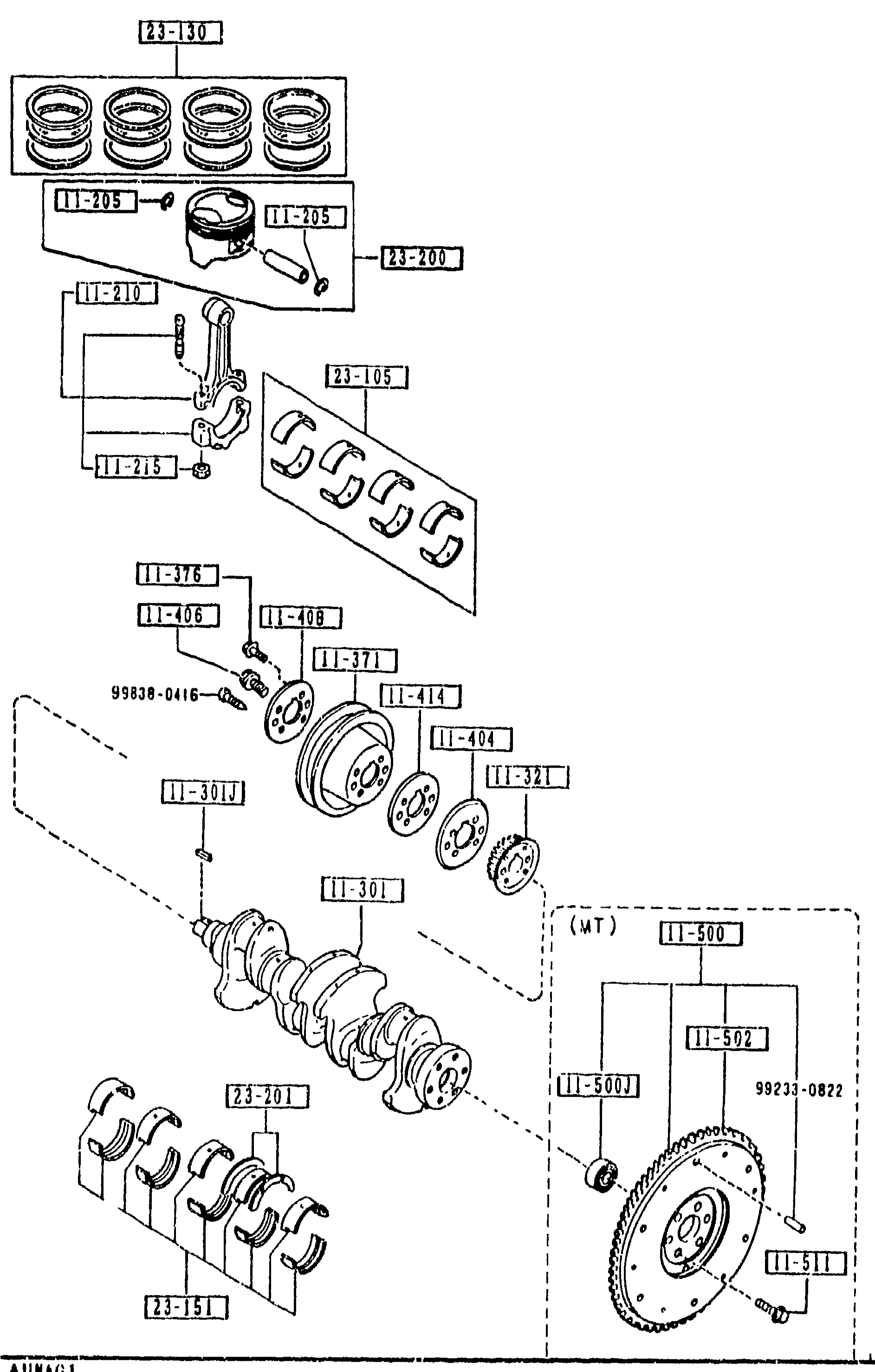
1100 -2 PISTON, CRANKSHAFT & FLYWHEEL
1-L3Continuation exploded view of B6 piston, crankshaft and flywheel — same drawing as the previous page. Highlights for this page's parts list are the flywheel-side components: pilot-bearing (11-502), ring gear (11-502 lock variant), flywheel lock-bolt (11-511), connecting-rod bearing sets (23-105) in STD / oversize 0.50 / 0.75 / 0.25 grades, piston-ring set (23-130) in matching grades, and crankshaft main-bearing set (23-151).
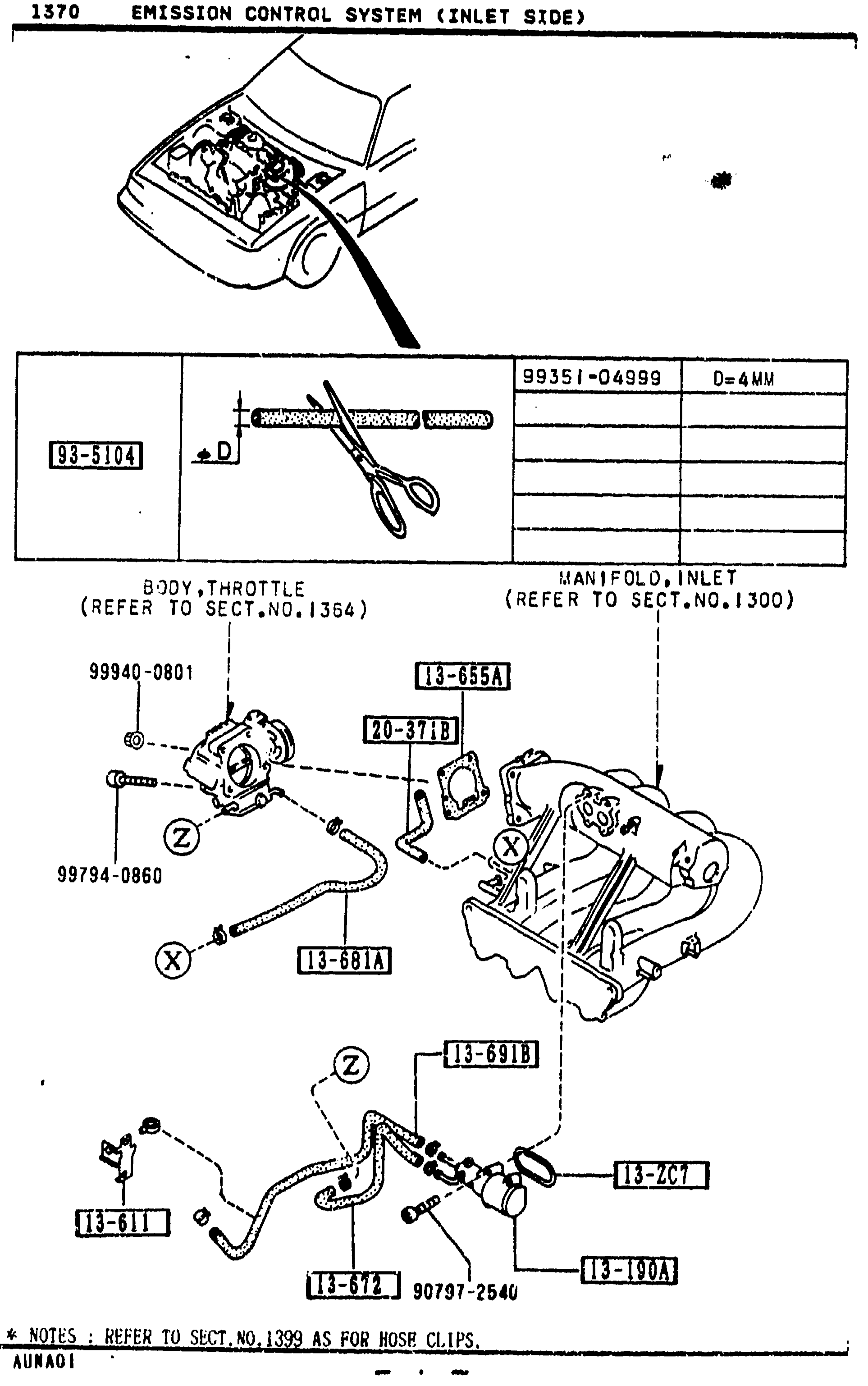
1370 EMISSION CONTROL SYSTEM (INLET SIDE)
1-L4Exploded view of emission control system (inlet side) for the MX-5 NA. Top sketch shows the engine bay with hood open. Middle inset shows the part 93-5104 hose-cutting tool with dimension D=4MM and reference 99351-04999. Lower diagram shows the throttle body (BODY, THROTTLE — refer to Sect. No. 1364) connected to the inlet manifold (MANIFOLD, INLET — refer to Sect. No. 1300), with callout balloons for parts 13-655A, 13-681A, 13-672, 13-611, 20-371B, 13-691B, 13-130A, 13-ZC7 and screws 99940-0801, 99794-0860, 90797-2540. Reference letters X, Y, Z mark connection points. Bottom note: 'REFER TO SECT.NO.1399 AS FOR HOSE CLIPS.'
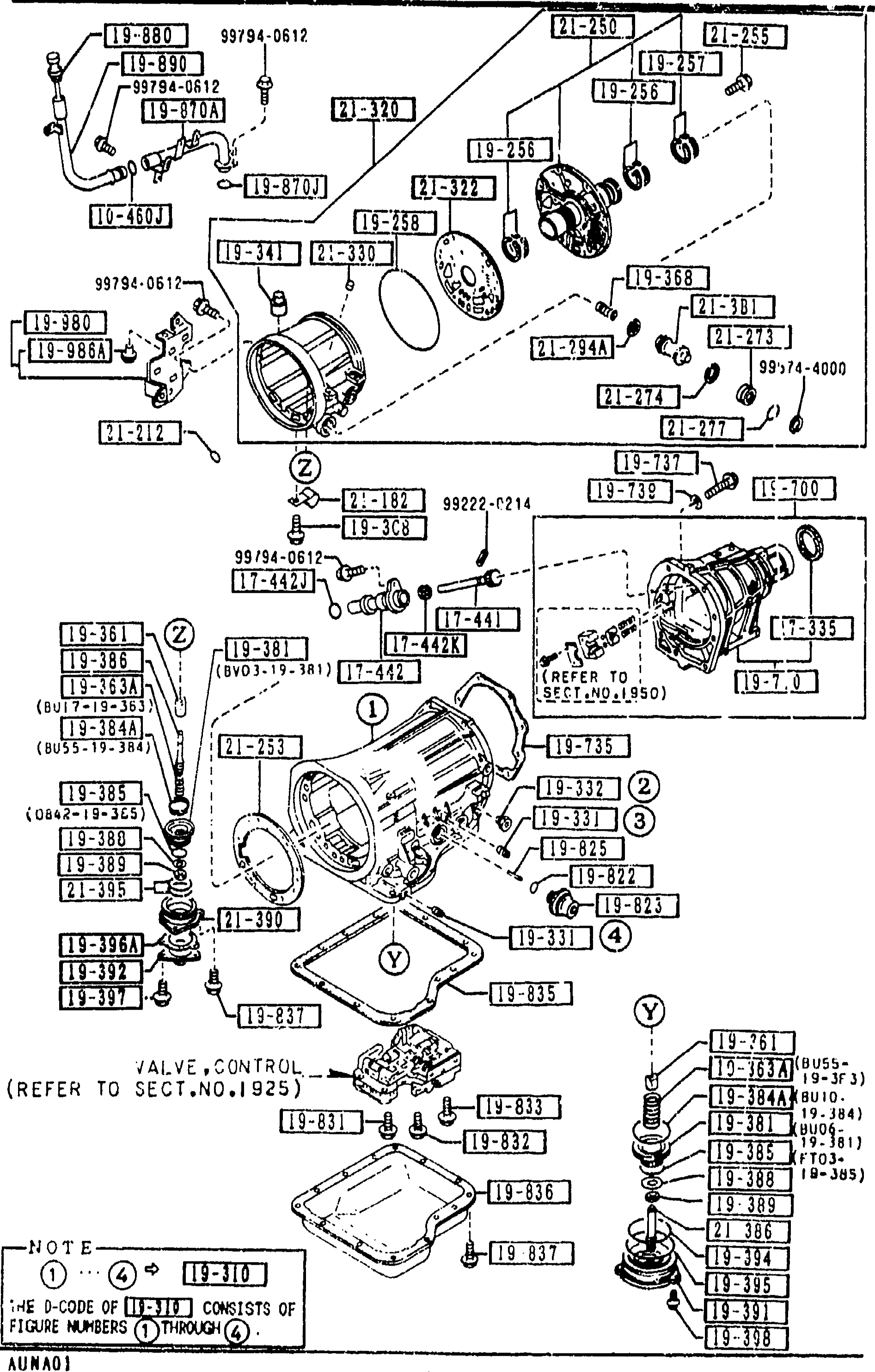
1920 TRANSMISSION CASE & MAIN CONTROL SYSTEM (AUTOMATIC)
1-M 7Continuation of the 1920 Transmission Case & Main Control System exploded view, indexing the extension-housing and vacuum-diaphragm sub-assembly: O-ring, asbestos gasket, bolts, extension housing, asbestos extension gasket, plain washer, O-ring seal, vacuum diaphragm and rod-diaphragm (balloons 1-10). The 'VALVE,CONTROL (REFER TO SECT.NO.1925)' callout and central NOTE balloon are repeated.
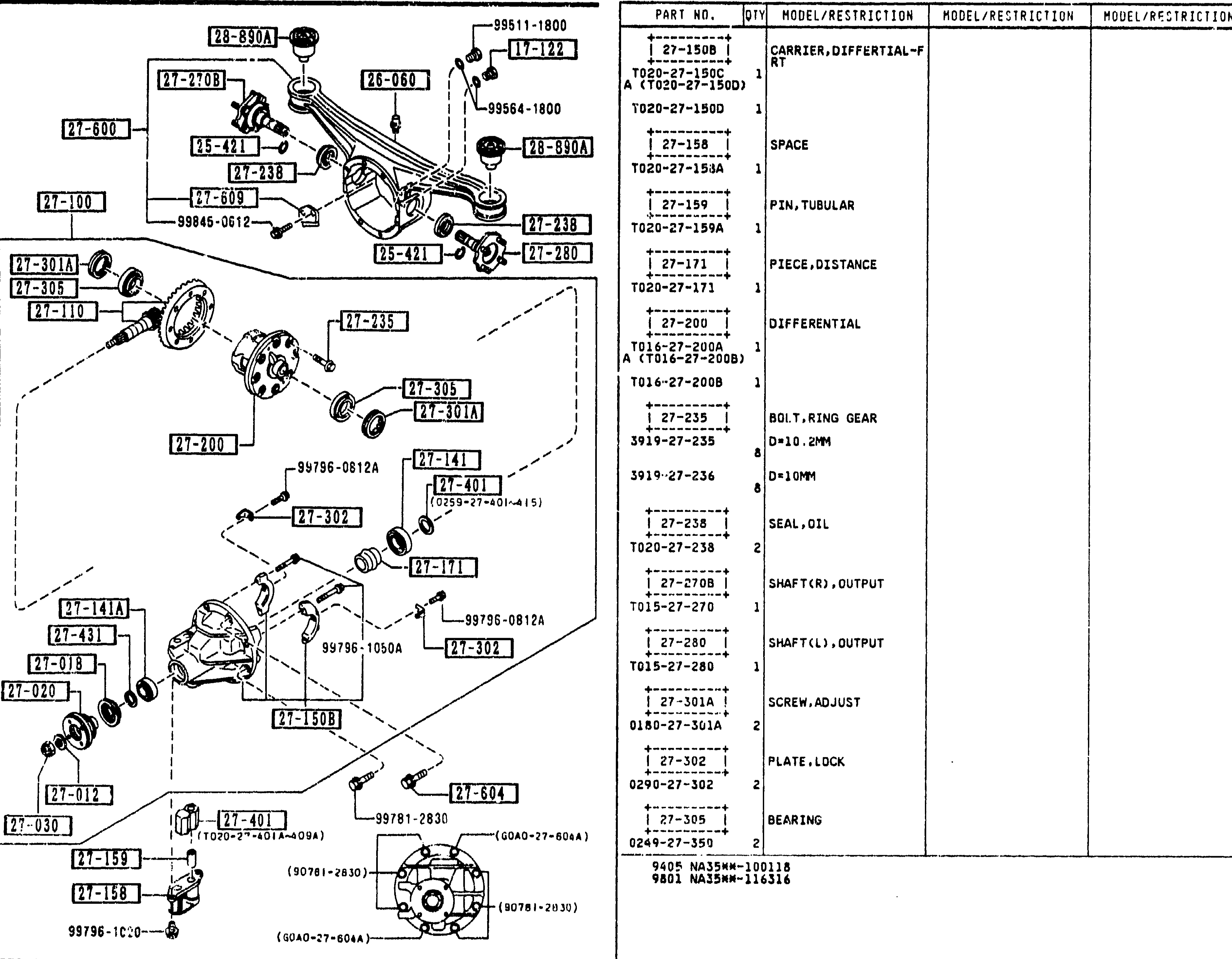
REAR DIFFERENTIALS (LIMITED SLIP DIFF.)
1-M11Exploded view of the rear differential (limited slip diff.) continuation. Surya merged the left-side exploded illustration and the right-side parts table into one region. The illustration shows differential carrier components including carrier (differential-FR) 27-150B, spacer 27-158, tubular pin 27-159, distance piece 27-171, differential 27-200, ring gear bolts (27-235 D=10.2mm, 27-236 D=10mm), oil seal 27-238, output shafts R/L (27-270B/27-280), adjust screw 27-301A, lock plate 27-302, bearing 27-305, with balloon callouts.
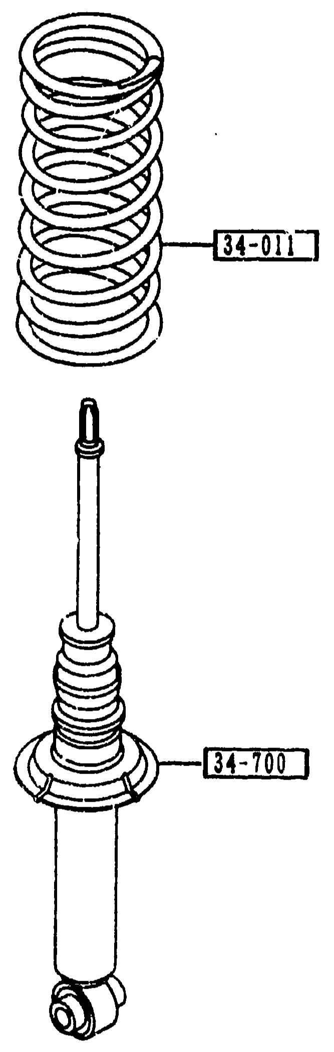
FRONT SPRING & DAMPER
1-M13Exploded view showing the front coil spring (callout 34-011) at top and the front damper / shock absorber (callout 34-700) below with its bump stopper and lower eyelet bushing. Detail figures from the front-suspension assembly drawn separately because the assembly D-code (28-1118) referenced this sub-section.
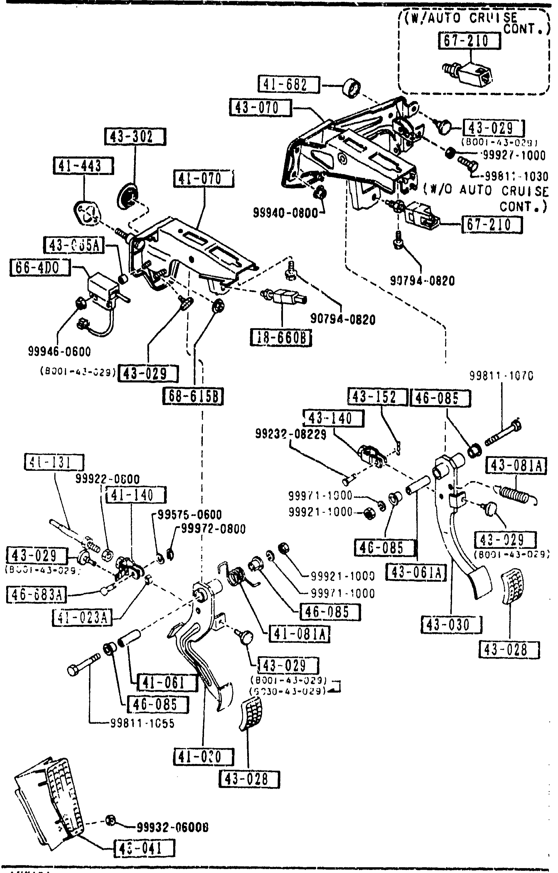
4300 CLUTCH & BRAKE PEDALS (MANUAL TRANSMISSION)
1-M15Exploded view of the clutch and brake pedal assemblies (manual transmission). Shows the pedal-bracket mounting frame with clutch switch (67-210), clutch pedal (41-030) with bush (41-023A), push rod (41-131), return spring (41-081A), clutch fork (41-140) and gasket (41-443), brake pedal (43-030) with stopper (43-029), pad (43-028), and assorted bolts. Variant indicators show w/ and w/o auto cruise control options. Page footer 1-M15.
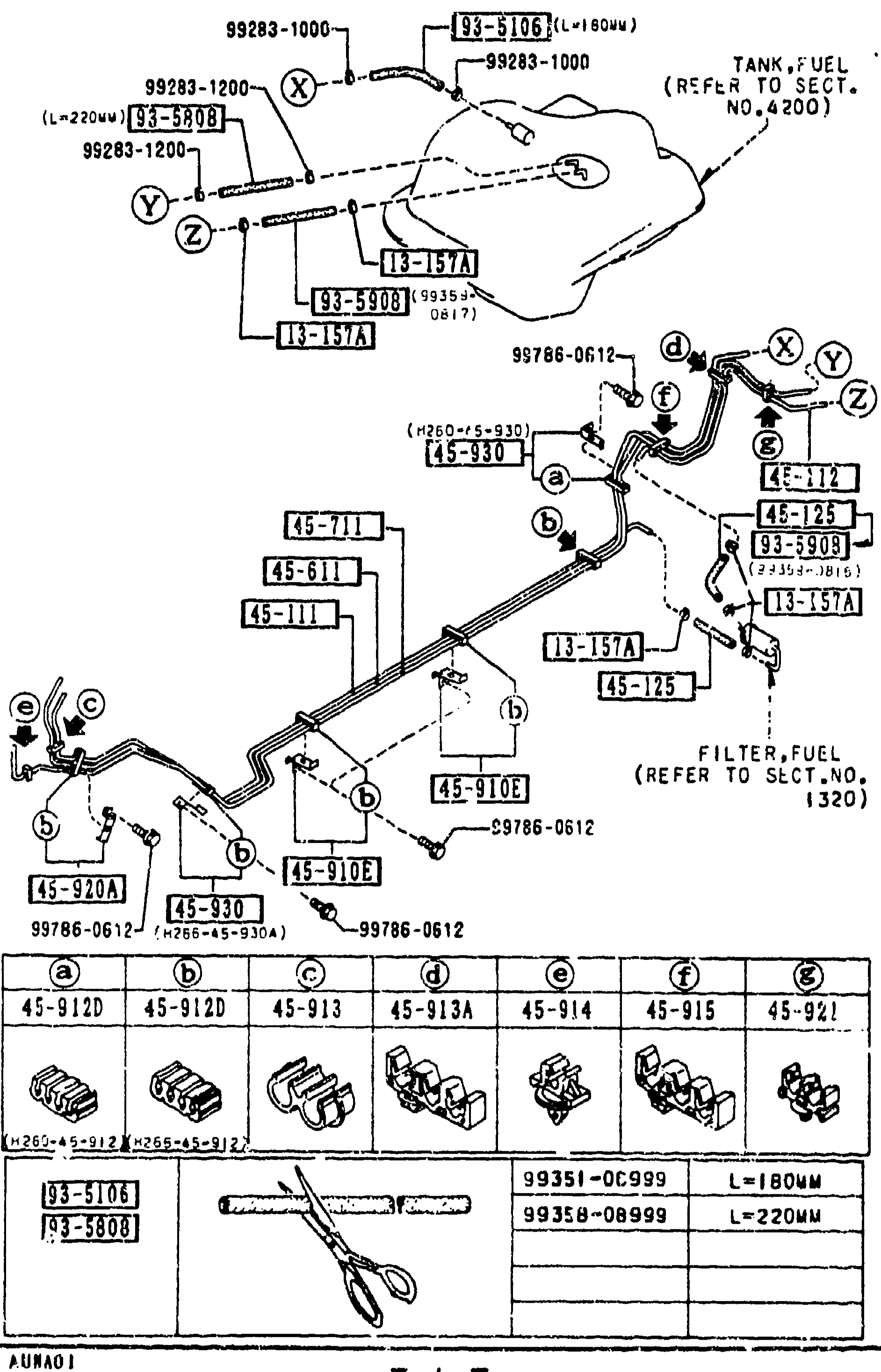
FUEL PIPINGS
1-M16Sheet 2 of the fuel pipings exploded view. Same underbody routing reprinted on the left to key the additional rows for clip 45-921, holder 'C' 45-930, and three cut-length hose pieces (93-S10E, 93-S80B, 03-S80B). Lower-left inset shows seven clip-shape variants (a-g) and a separate inset for the two cut-length hose pieces with their part numbers and lengths.
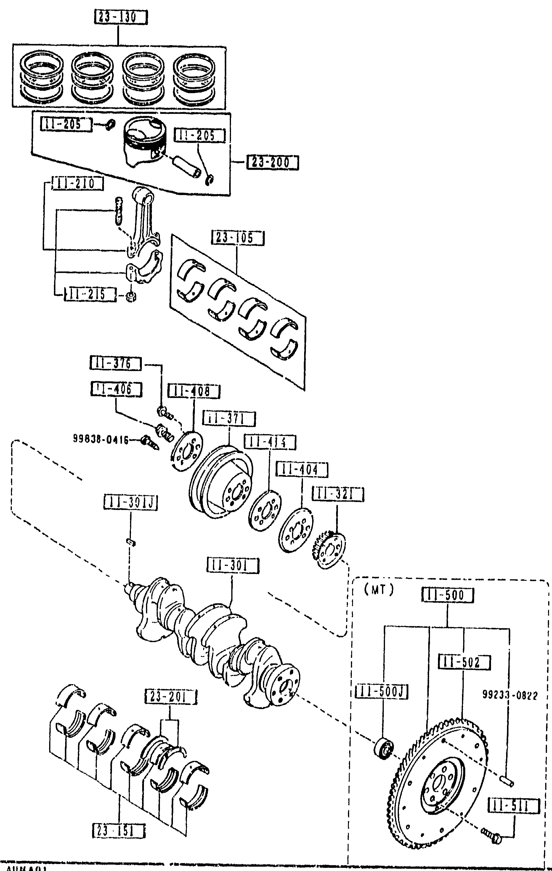
1100 -3 M PISTON, CRANKSHAFT & FLYWHEEL
1-M3Third sheet of the piston/crankshaft/flywheel exploded view — same drawing reprinted to carry the remaining parts. Highlights for this page's catalog: piston ring set continued (23-130) with O.S. 0.25 grade, piston sets (23-200) STD / 0.50 / 0.20 for AT and MT variants, connecting-rod metal sets (23-105 cont'd) with several AT/MT cutoffs at 9601, and crankshaft thrust-bearing sets (23-201) STD / 0.50 / 0.75 / 0.25 with 0405 cutoffs.
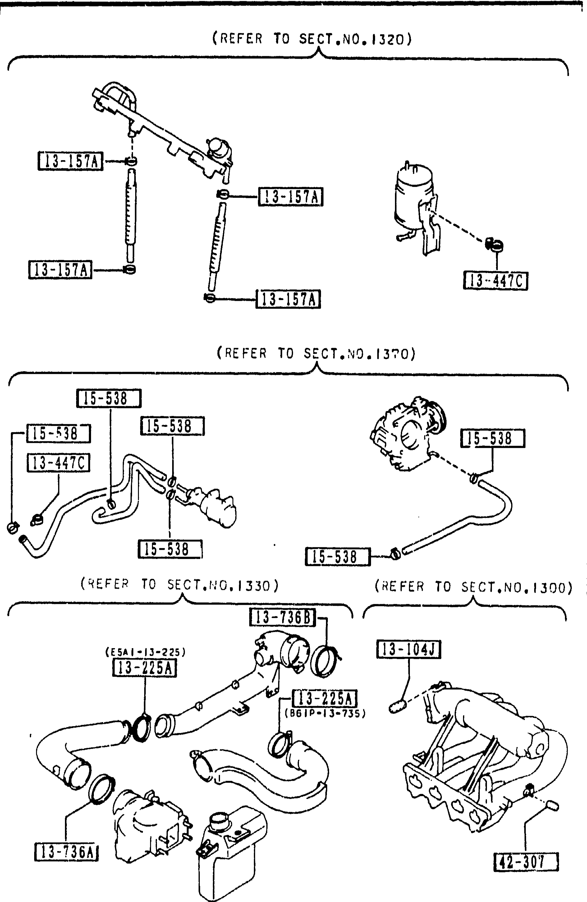
1399 CAP & HOSE CLIP (INLET & EXHAUST SIDE)
1-M4Composite exploded view of cap & hose clips on the inlet and exhaust side. Top inset 'REFER TO SECT.NO.1320' shows fuel-line hose connections with clamps 13-157A and a fuel filter with clamp 13-447C. Middle inset 'REFER TO SECT.NO.1370' shows the air-injection hose routed across a component with multiple 15-538 clamps and 13-447C. Bottom-left inset 'REFER TO SECT.NO.1330' shows an air-intake duct with clamps 13-225A and 13-736B. Bottom-right inset 'REFER TO SECT.NO.1300' shows the intake manifold with clip 13-104J. Cap 42-307 also referenced. Page footer reads '1-M 4'.
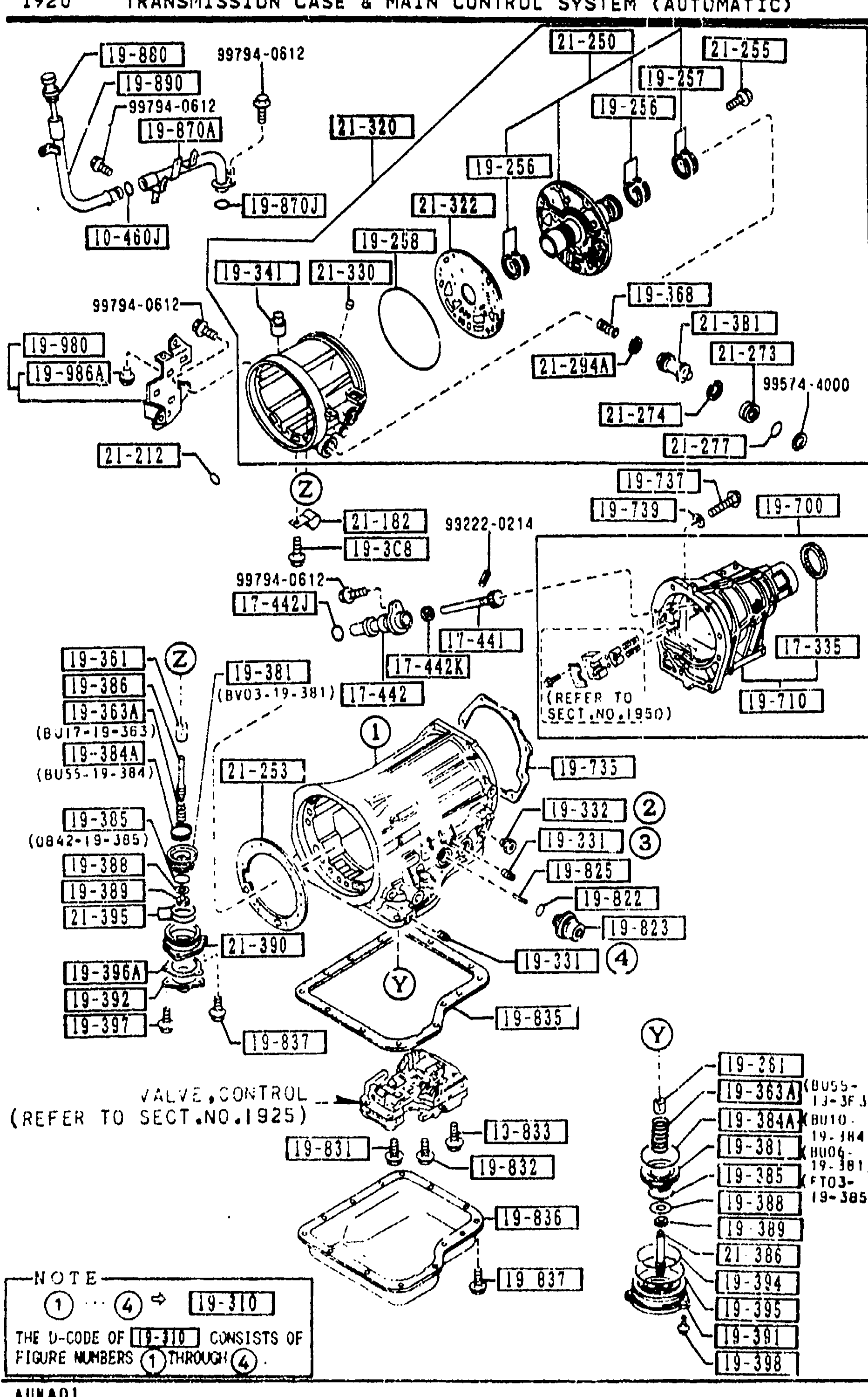
1920 TRANSMISSION CASE & MAIN CONTROL SYSTEM (AUTOMATIC)
1-N 7Continuation of the 1920 Transmission Case & Main Control System exploded view. This page indexes control-valve bolts, the oil pan and its gasket, oil-pan bolts, filler tube, O-ring, oil-level gauge, filter tube, bracket and rubber bush (balloons 1-12). The 'VALVE,CONTROL (REFER TO SECT.NO.1925)' callout and the central NOTE balloon are repeated.
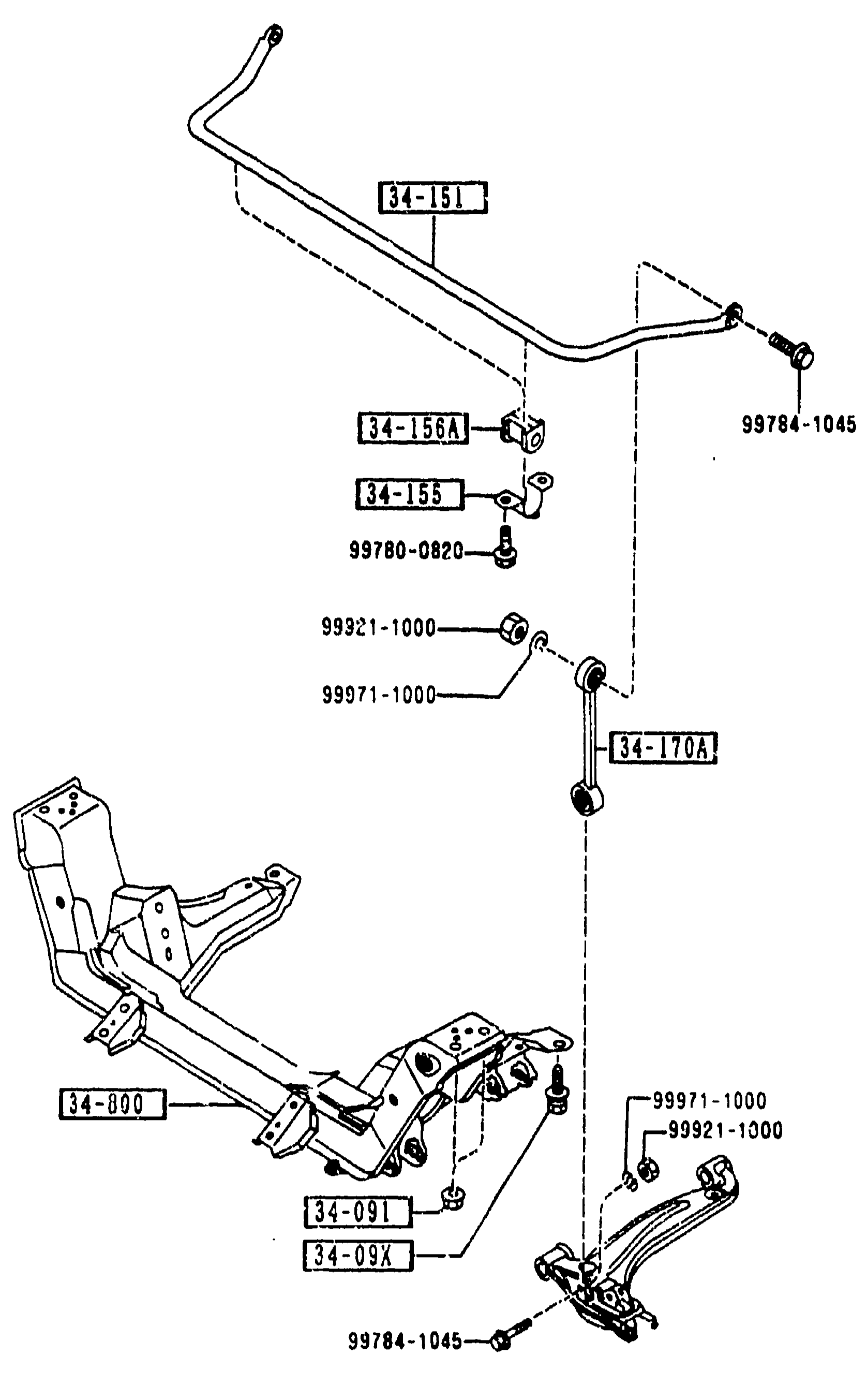
CROSSMEMBER & STABILIZER
1-N13Exploded view of the front crossmember/sub-frame (34-800) and stabilizer/anti-roll bar (34-151). Shows stabilizer bar with rubber mount brackets (34-156A) and clamp plates (34-155), end links (34-170A) connecting stabilizer to lower control arms, sub-frame mounting bolts (34-09X / 34-091), and assorted hardware (99784-1045, 99780-0820, 99921-1000, 99971-1000).
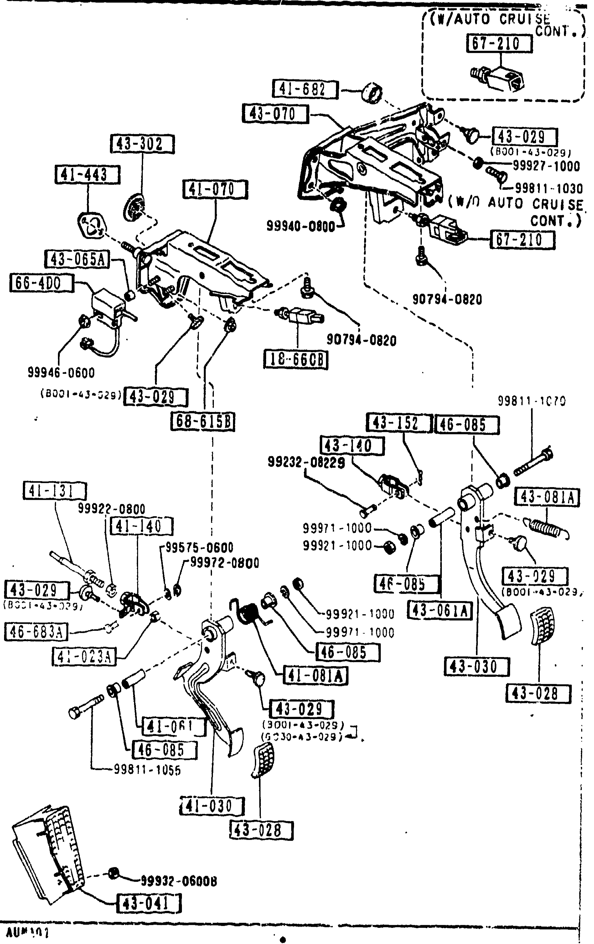
4300 CLUTCH & BRAKE PEDALS (MANUAL TRANSMISSION)
1-N15Continued exploded view of clutch and brake pedal assemblies (manual transmission, page 4300-2). Same illustration as the preceding page, highlighting components in the right-side table: pedal foot rest, pedal pipe, spacer, master cylinder bracket (base + opt), return spring, brake fork, snap pin, brake pedal grommet, bushings, clutch-cut switch, and brake light switch. Variant indicators show w/ and w/o auto cruise control.
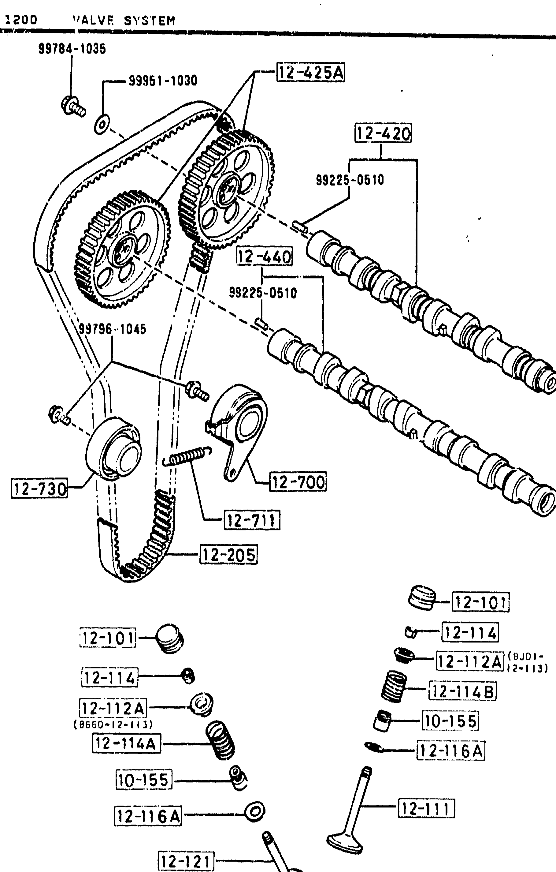
1200 VALVE SYSTEM
1-N3Exploded view of the B6 DOHC valve system. Top half shows the twin overhead camshafts driven by the timing belt (12-205), with the camshaft sprockets (12-420, 12-425A), idler pulley (12-440), tensioner assembly (12-700 / 12-711) and tensioner bracket (12-730). Bottom half shows the valve train: hydraulic lash adjusters (12-101), inlet valves (12-111), exhaust valves (12-121), valve seals (10-155), upper & lower valve-spring seats (12-112A / 12-116A), inner & outer valve springs (12-114, 12-114A, 12-114B) and valve cotters (12-114).
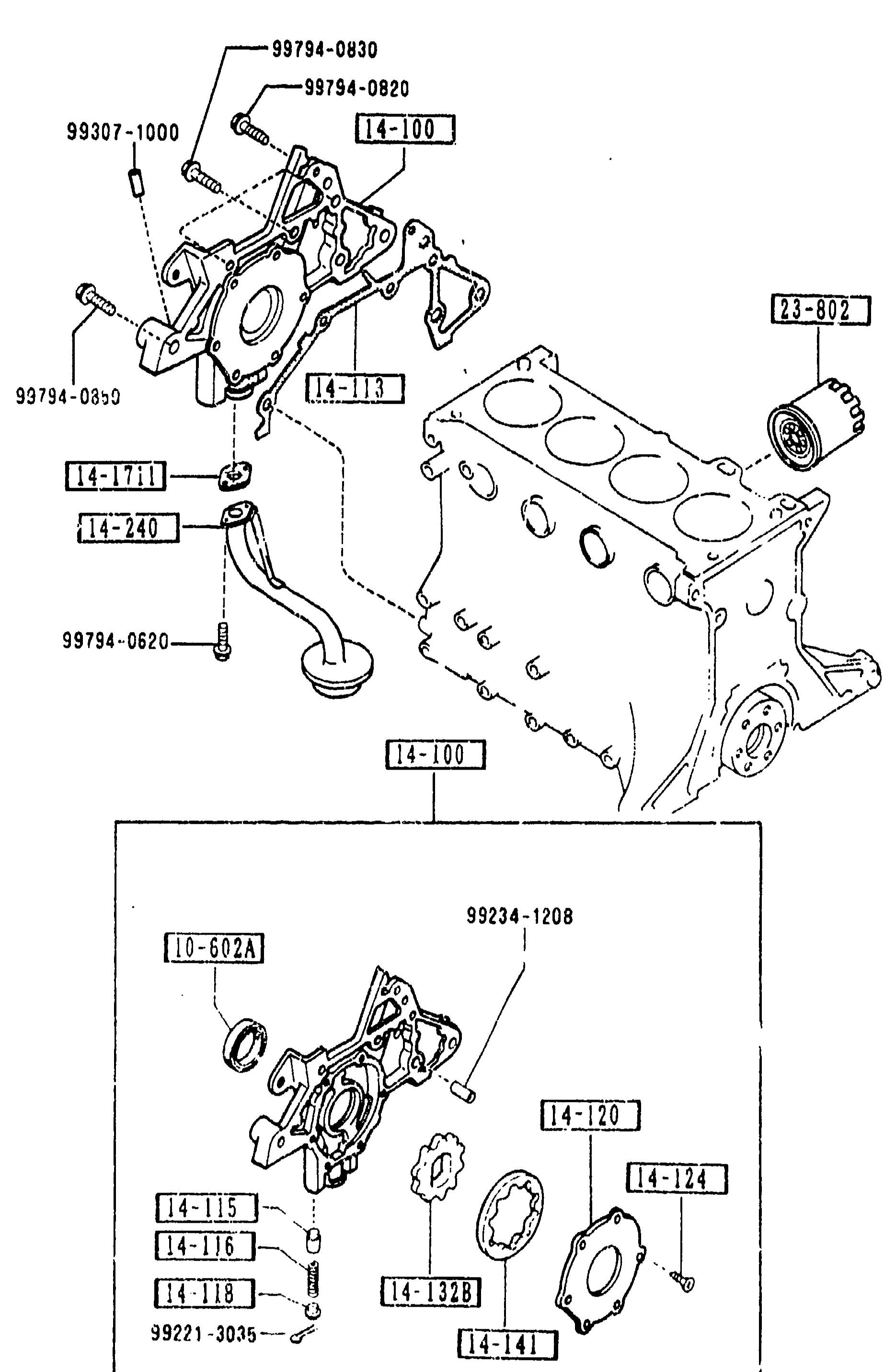
1400 OIL PUMP & FILTER
1-N4Exploded view of the B6 engine oil pump and filter assembly for the MX-5 NA. Top half shows the oil pump housing 14-100 mounted to the front of the cylinder block, with seal 10-602A, gasket 14-113, plunger 14-115, pressure spring 14-116, sheet spring 14-118, cover 14-120, screws 14-124, gears 14-1328 (inner) and 14-141 (outer), oil strainer gasket 14-1711, strainer 14-240, oil filter cartridge 23-802, and various screws 99794-0820, 99794-0830, 99307-1000, 99794-0612, 99794-0620. Lower inset shows the oil pump body with the gear set in detail and the strainer 10-602A + 99234-1208 + screw 99231-3035. Page footer black bar is partly obscured but shows '1-N' followed by an unreadable digit.
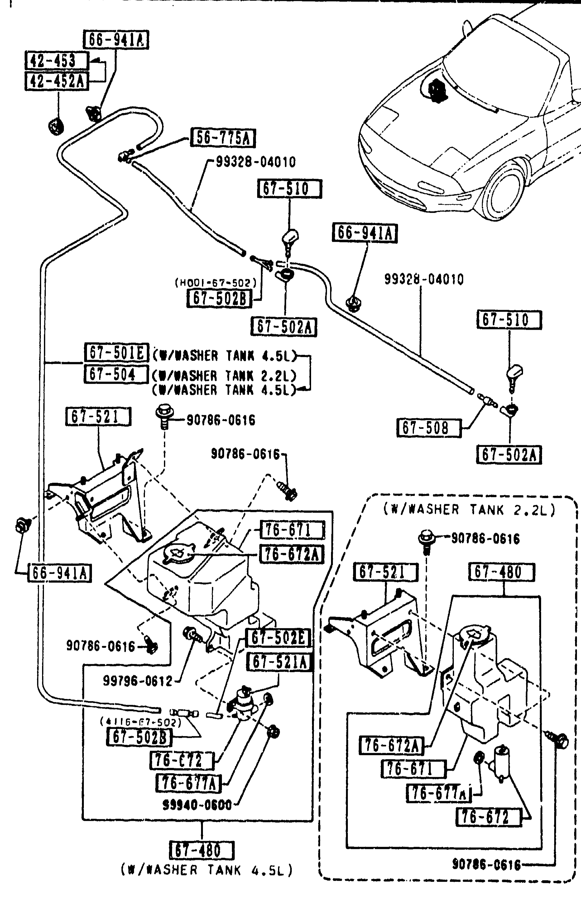
6720 WINDSHIELD WASHER
2-115Exploded view of windshield washer system showing the washer reservoir tank (with both 2.2L and 4.5L tank variants), washer pump/motor, hose routing from tank along the cowl/firewall to the hood/cowl area, and the washer nozzle on the hood. Numbered balloon callouts identify individual parts and fasteners. A small vehicle-front line drawing in the upper right area of the figure shows the washer nozzle location on the hood. Two alternative tank-bracket sub-assemblies (one labelled W/WASHER TANK 2.2L and one labelled W/WASHER TANK 4.5L) are shown side by side at the bottom of the figure.
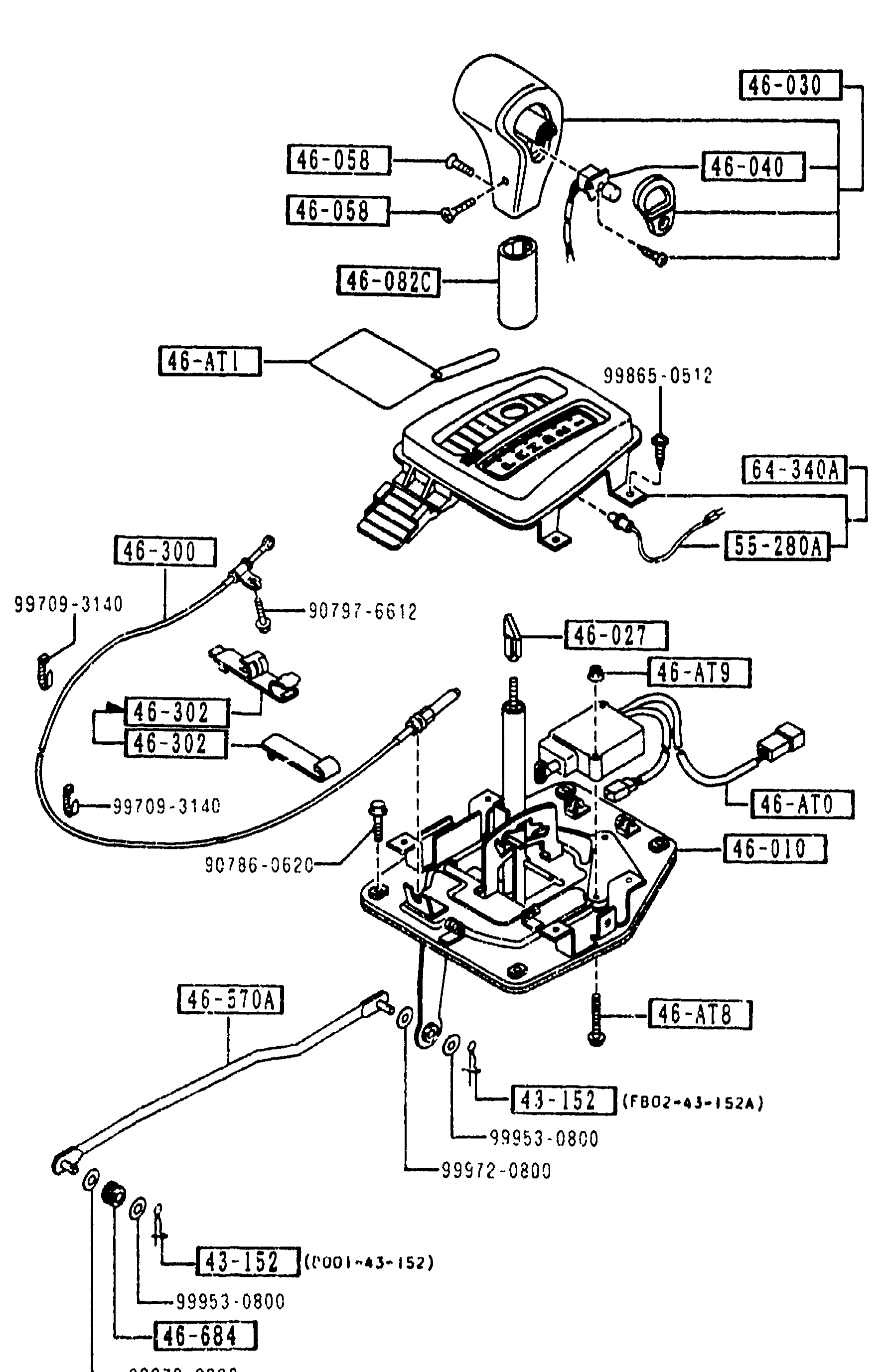
4600 CHANGE CONTROL SYSTEM (AT)
2-C 3Exploded view of the AT (automatic transmission) change control / selector assembly. Shows the selector lever knob (46-030), shift-lock actuator (46-AT0), caution-change tag (46-AT1), screws (46-AT8), select-lever cover (46-082C), select lever (46-010), shift-lock related parts (46-040, 99865-0512), change-lever cam and knob (46-027, 46-AT9), over-drive control switch (46-AT0), screws (46-058), inner-lock cable assembly (46-300, 46-302), rear selector rod (46-570A), bushings (46-684) and the indicator bulb & socket (55-280A, 64-340A). Numerous hardware callouts (99709-3140, 90797-6612, 90786-0620, 99953-0800, 99972-0800, 43-152, F802-43-152A, D001-43-152) point to bolts, washers and clips. The whole assembly is oriented with the selector lever at top and the cable run extending to the bottom-left toward the transmission.
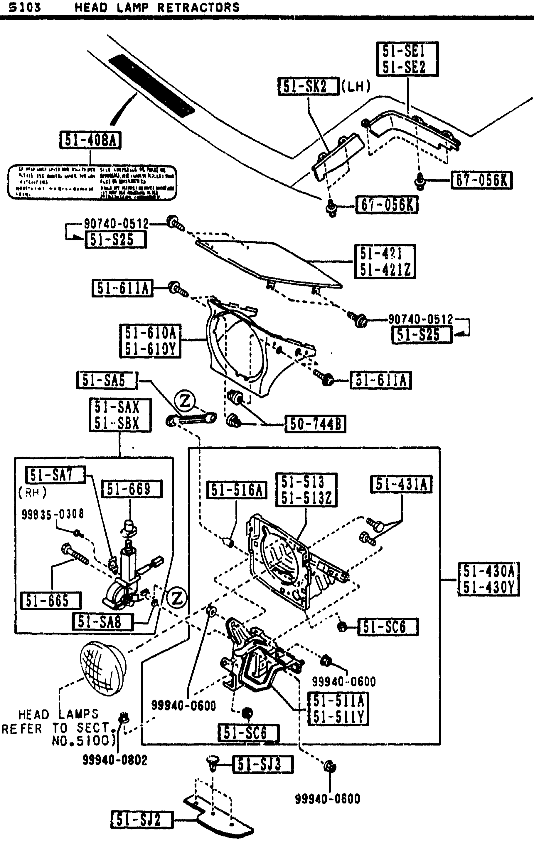
HEAD LAMP RETRACTORS
2-C 6Exploded view of the head lamp retractor assembly for the MX-5 (NA). Shows the retractor housing, bezel (R/L), motor-retract bolts, boots, screws and rivets. Includes a callout to the head lamp itself with reference 'HEAD LAMPS (REFER TO SECT NO. 5100)'. Balloon callouts include 51-SE1/51-SE2, 51-SK2(LH), 51-408A, 67-056K, 90740-0512, 51-S25, 51-421/51-421Y, 51-611A, 51-610A/51-610Y, 51-SAS, 50-Z483, 51-611C, 51-SAT(RH), 51-SAX/51-SBX, 51-665, 51-S13/51-S13Z, 51-431A, 51-430A/51-430Y, 51-668, 51-SA8, 51-516A, 51-SC6, 99835-0108, 99940-0600, 51-511A/51-511Y, 51-SJ3, 99940-0802, 51-SJ2.
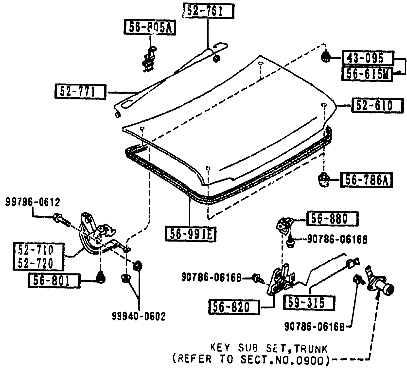
TRUNK LID
2-C 7Exploded view of the trunk lid (boot) — repeat of the previous page (5260 -2 M TRUNK LID continuation). Shows the lid panel [52-610], balance spring (R) [52-761] and (L) [52-771], holder for balance spring [56-805A], grommet [43-095], drain plug [56-615M], rubber cushion [56-786A], weatherstrip [56-991E], striker [56-880], hinges (R/L) [52-710, 52-720], hinge cushion [56-801], lock [56-820], clips [59-315], and bolts [99796-0612, 90786-06168, 90786-0616B, 99940-0602]. Note 'KEY SUB SET, TRUNK (REFER TO SECT.NO.0900)' under the lock callout.
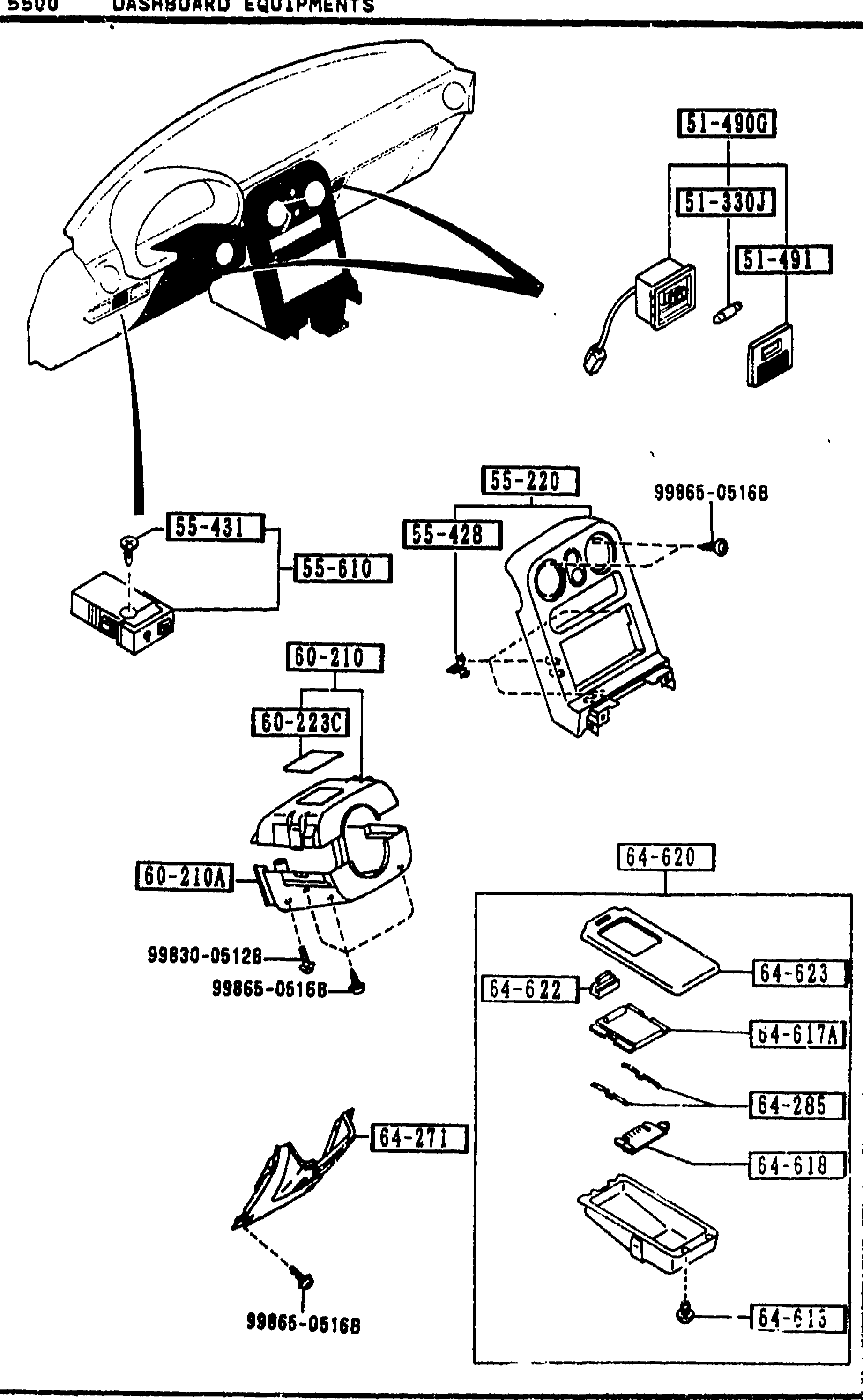
DASHBOARD EQUIPMENTS
2-C 9Exploded view of the MX-5 dashboard equipments. Top-left shows the upper dashboard area with the instrument cluster cowl and personal-lamp lens. Centre-left shows the centre console panel and meter hood with a 99865-0516B fastener call-out. Lower-left shows the steering column upper/lower covers (60-210 / 60-210A / 60-2231 / 60-223C). Lower-right shows the console box trim group (64-620, 64-622, 64-617A, 64-285, 64-618, 64-615, 64-623, 64-271) with 99830-0512B / 99865-0516B fasteners.
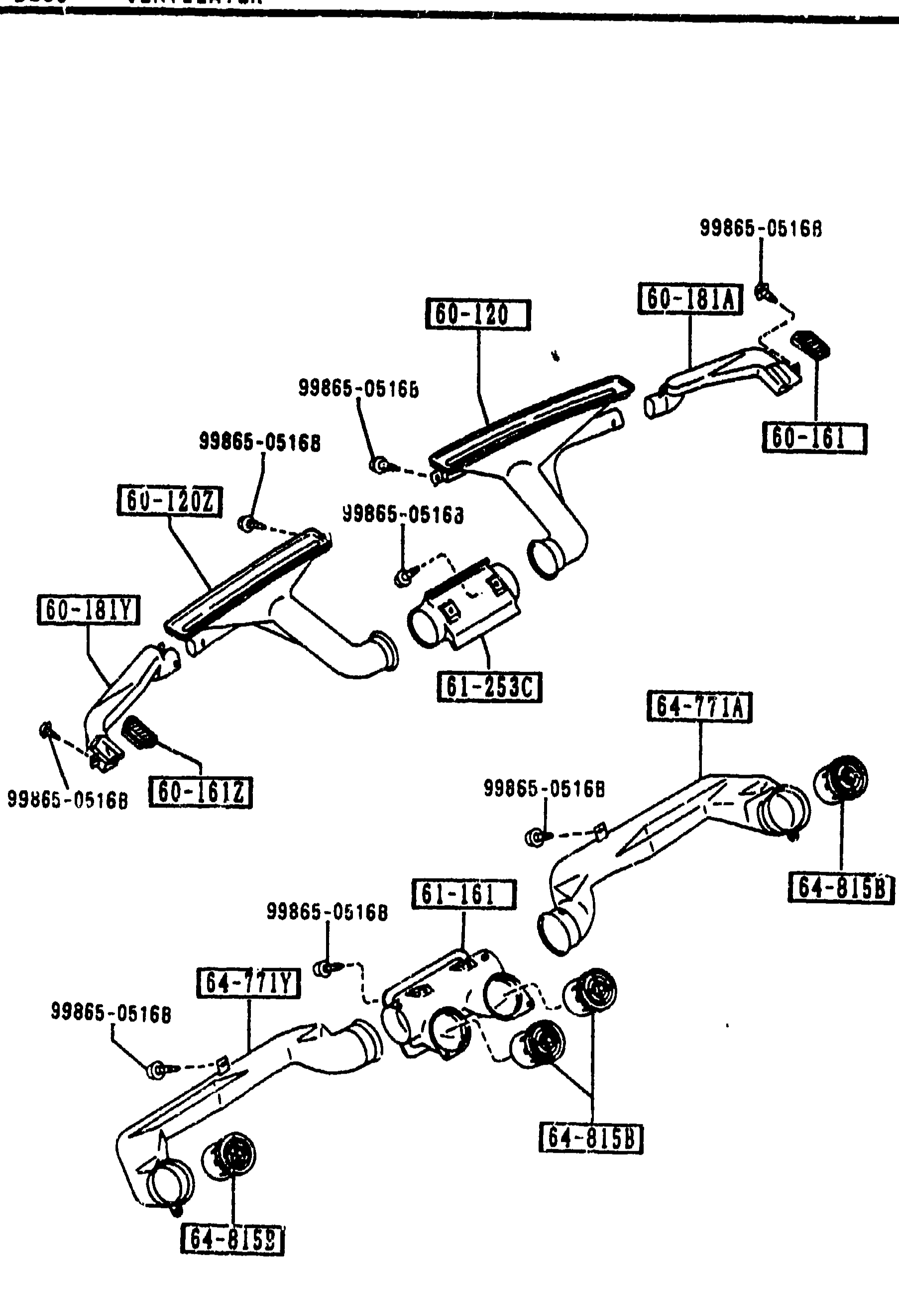
VENTILATOR
2-C10Exploded view of group 5580 (VENTILATOR). Shows defroster nozzles (60-120, 60-120Z), side demister grilles (60-161, 60-161Z), side demister ducts (60-181A, 60-181Y), center duct (61-161), defroster hose (61-253C), centerleg ducts no.1 R and L (64-771A, 64-771Y), ventilator louvers (64-815B, 64-815S), tapping screw (99865-05168) and clip (60-612, 64-71Y, 64-31SX).
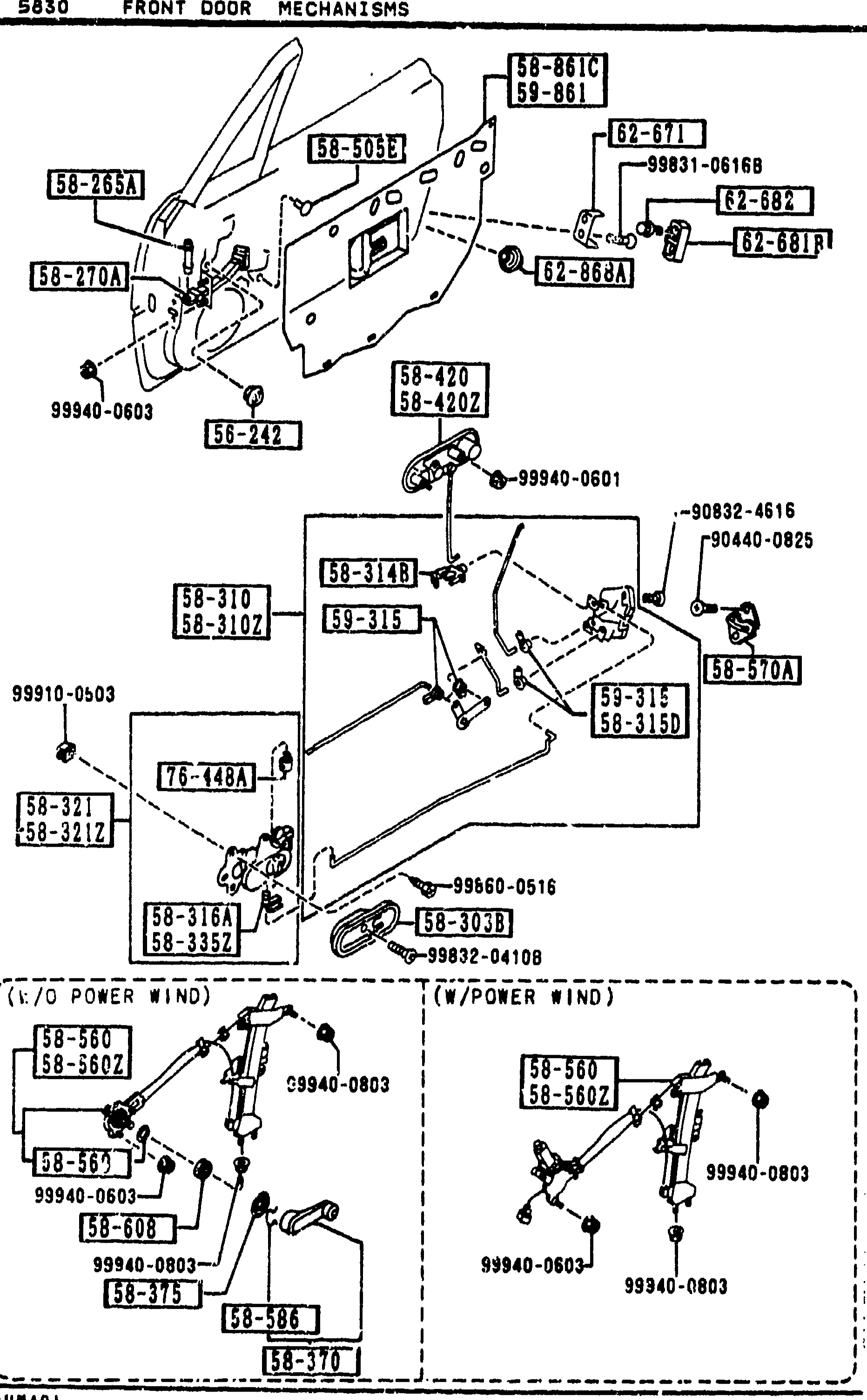
FRONT DOOR MECHANISMS
2-C11Exploded view of front door internal mechanisms: latch, lock/striker, door checker, inner and outer handles, window regulator (both with/without power-window variants), drain plug. Lower-left has two boxed insets showing manual-window vs power-window regulator assemblies. Callouts include 58-861C/58-861 (latch), 58-503E (assembly), 58-265A (pin, checker), 58-270A (checker, door), 58-303B (cover, inner handle), 58-420/58-420Z (handle assembly), 58-310/58-310Z (lock R/L door), 58-310B (joint), 58-31AB (joint), 58-315 (clip R), 58-316A (clip), 58-321/58-321Z (handle inner R/L), 58-335Z (clip L inner handle), 58-370 (handle regulator), 58-560/58-560Z (manual regulator R/L), 58-561, 58-608, 58-375, 58-586, 58-602/58-602Z, 76-148A, 82-671/82-682/82-868A/82-881 (lock components), and several fasteners (99940-xxxx, 99831-xxxx, 99832-xxxx, 99910-xxxx, 99960-xxxx, 90832-4616, 90440-0825).
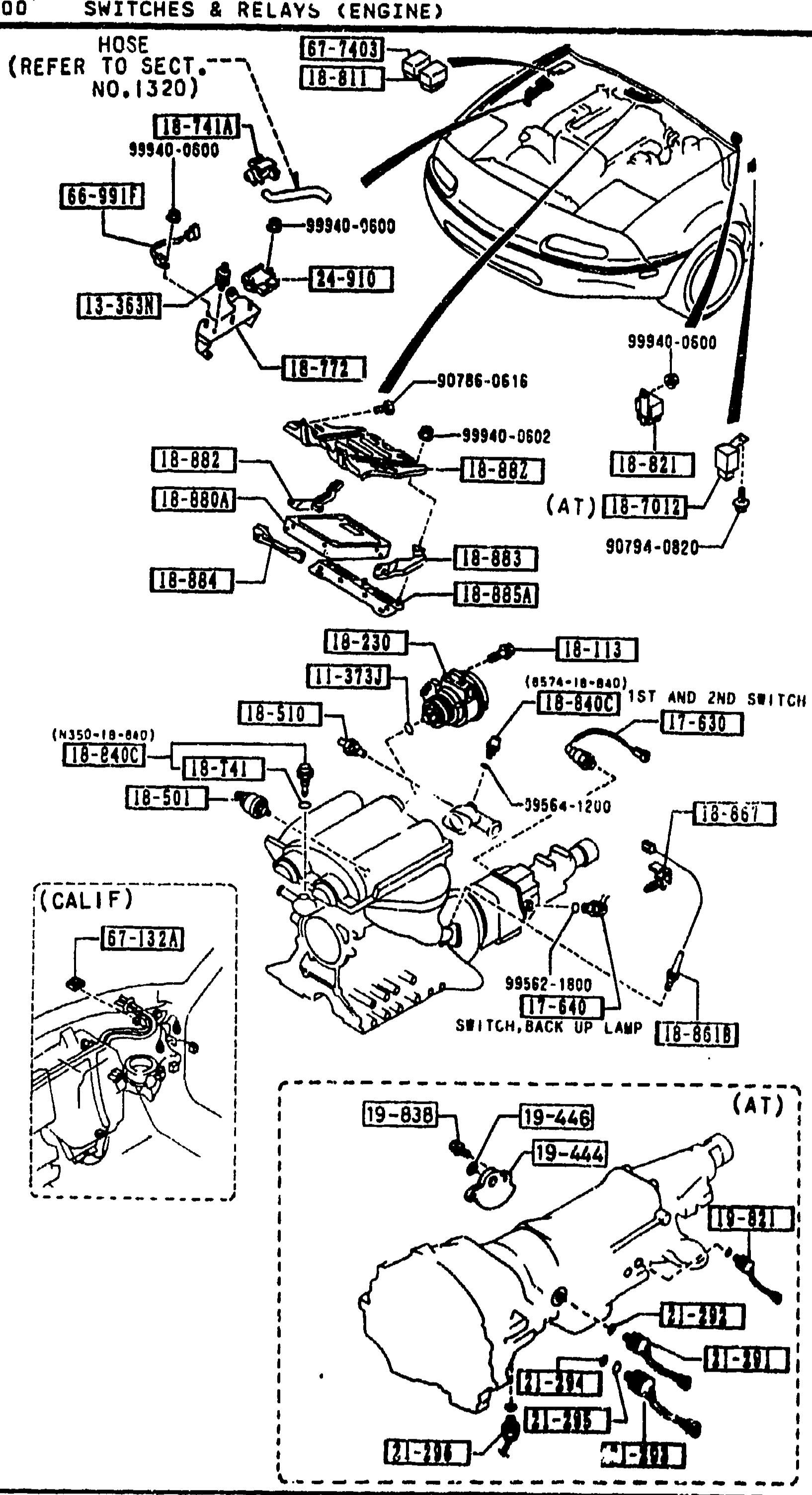
SWITCHES & RELAYS (ENGINE)
2-C14Exploded view of switches & relays (engine) for MX-5 NA. Top portion shows an engine bay overview with a hose (REFER TO SECT. NO. 1320) and various components like 18-882, 18-883, 18-883A, 18-884, 18-885A, 90786-0616, 99940-0500, 99940-0600, 90786-0616. Bottom shows transmission with (CALIF) note and parts 19-444, 19-446, 18-510, 14-340, 19-440, 19-638, 11-540, 99562-1800, 04574-0402, 67-7403, etc. Includes a note '(AT)' for automatic transmission components and (CALIF) for California-spec parts. Connections labeled '1ST AND 2ND SWITCH', 'SWITCH, BACK UP LAMP'.
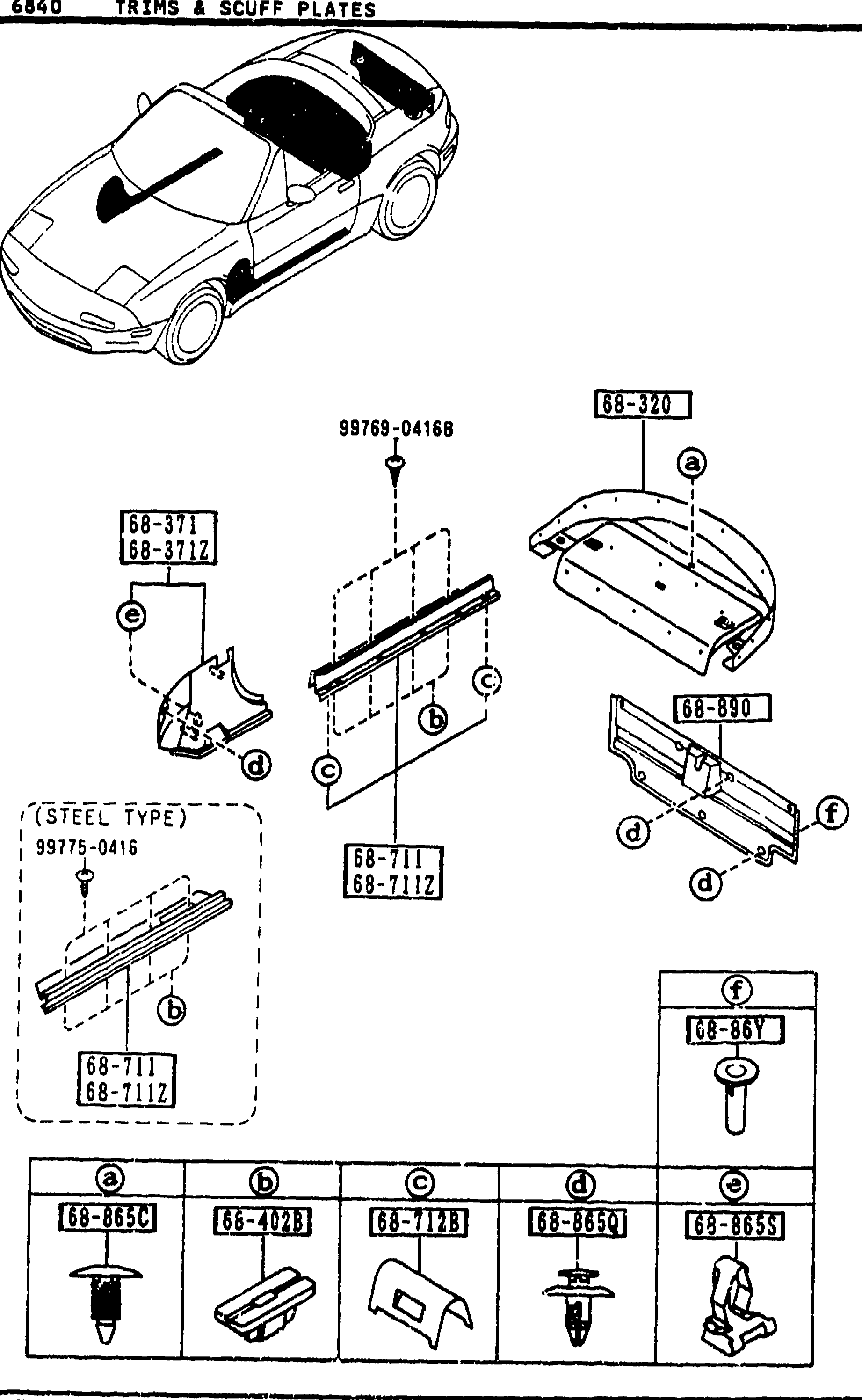
6840 TRIMS & SCUFF PLATES
2-C16Upper-left isometric MX-5 line drawing showing the rear-package area highlighted. Below it, multiple sub-figures detail the trim parts: rear package tray (68-320), front-side trims left/right (68-371 / 68-371Z), front scuff plates (68-711 / 68-711Z) in both PLASTIC TYPE and STEEL TYPE variants, trim 68-890, cap/seal trunk end trim 68-86Y, and a bottom row of five fastener illustrations (a)68-865C, (b)68-A0Z3, (c)68-712B, (d)68-865K, (e)68-865S keyed to letter callouts in the larger views.
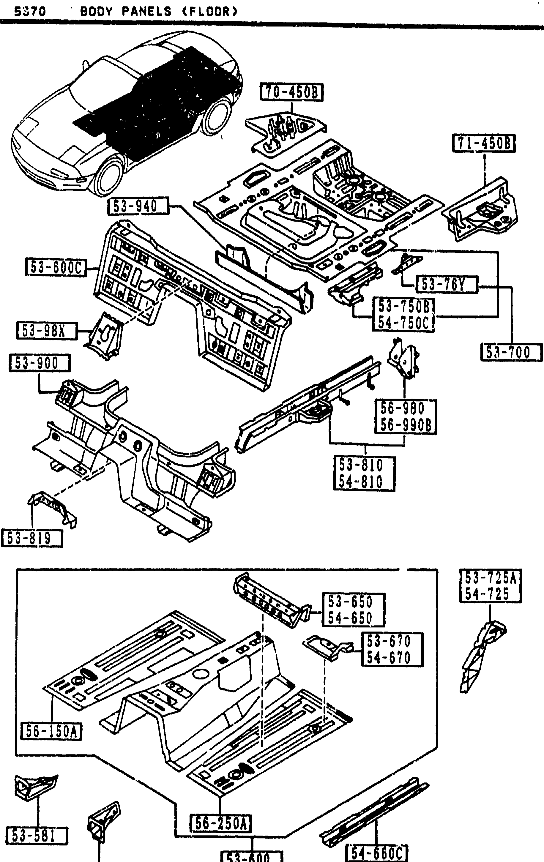
BODY PANELS (FLOOR)
2-C8Exploded view of the MX-5 NA floor panels. Top sub-diagram shows the underbody from front-isometric with balloons including 55-501 (junction R front floor), 53-600 (pan floor front), 53-600A (pan floor center), 53-650 (member no.2 R cross floor), 53-670 (brkt R seat-F floor pan), 53-700 (pan floor rear), 53-7108 (gusset no.3 R C floor pan), 53-7508 (plate R side-rear F floor), 53-767 (plate, nut-trunk pad R pan), 53-810 (frame R rear side), 53-819 (bracket parking cabl pan), 53-900 (member no.3 cross). Bottom-left sub-diagram shows the floor pan from above with callouts 53-816, 53-617, 54-810, 54-740, 56-104.
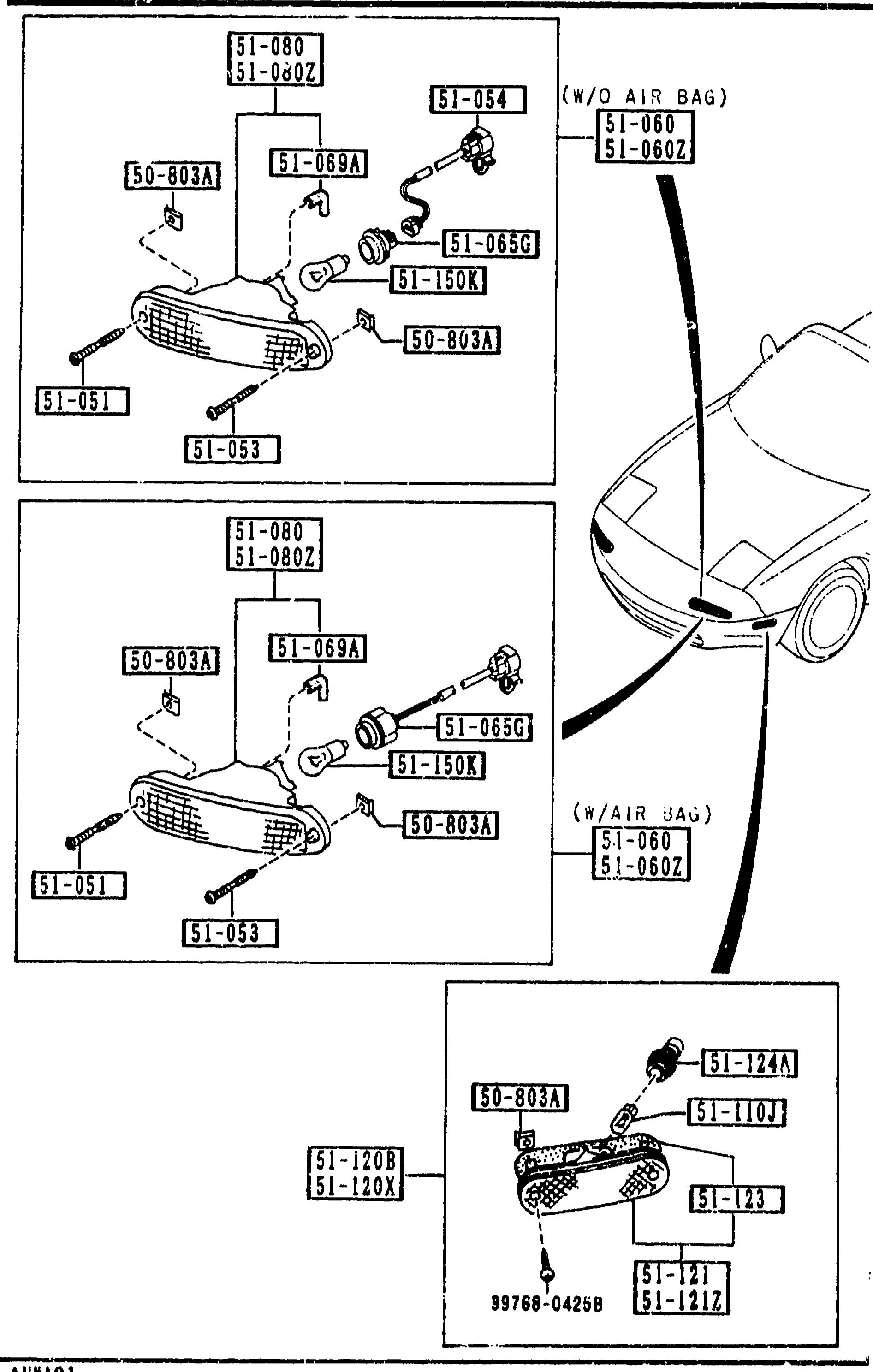
FRONT COMBINATION LAMPS
2-D 6Exploded view of MX-5 front combination lamp assembly. Two stacked lamp diagrams (W/O AIR BAG vs W/AIR BAG variants for 51-060/51-060Z lamp set), a small vehicle silhouette in the middle showing front-lamp location, and a third smaller exploded view at the bottom for the side-turn/lens housing (51-120B / 51-120X). Callouts: 51-080, 51-080Z, 50-803A, 51-051, 51-053, 51-069A, 51-054, 51-060, 51-060Z, 51-065G, 51-150K, 51-120B, 51-120X, 51-110J, 51-124A, 51-123, 51-121, 51-121Z, 99768-0425B.
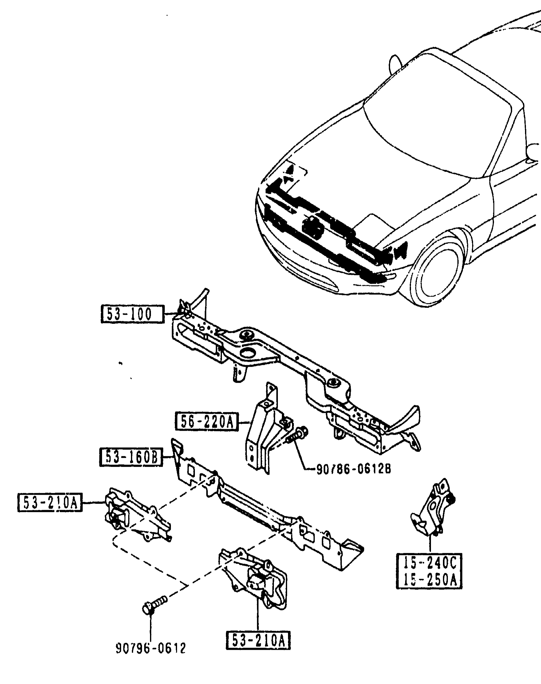
BODY PANELS (FRONT)
2-D 7Front body panels exploded view. Top: 3/4 perspective view of the front of the car (NA Miata) with the bonnet open showing the engine compartment and radiator-shroud / front-end carrier in place. Bottom: exploded illustration of the radiator-shroud carrier assembly [53-100] with cross member [53-160B], bumper brackets [53-210A], bonnet-lock stay [56-220A], radiator brackets R/L [15-240C, 15-250A], and fasteners [90786-06128, 90796-0612].
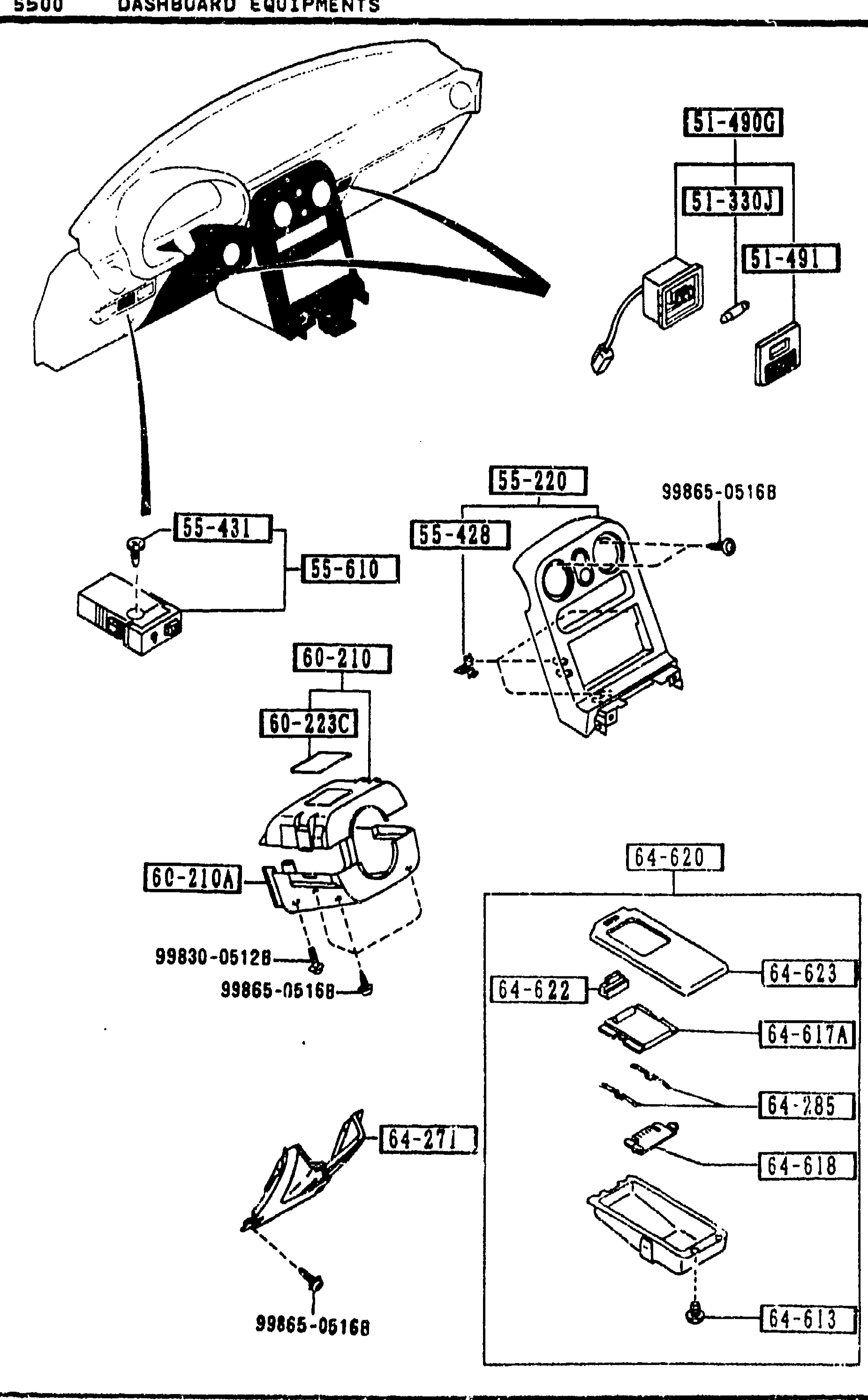
DASHBOARD EQUIPMENTS
2-D 9Continuation exploded view of the MX-5 dashboard equipments — same artwork as the previous page (instrument cluster cowl + steering column covers + console-tray cluster). Balloons identify upper-cluster bulbs/personal lamp (51-330J, 51-491, 51-4900), centre-stack panel and meter hood (55-220, 55-431, 55-428, 55-610), column covers (60-210, 60-210A, 60-223C), and the console ash-tray group (64-620, 64-622, 64-617A, 64-285, 64-618, 64-271, 64-623).
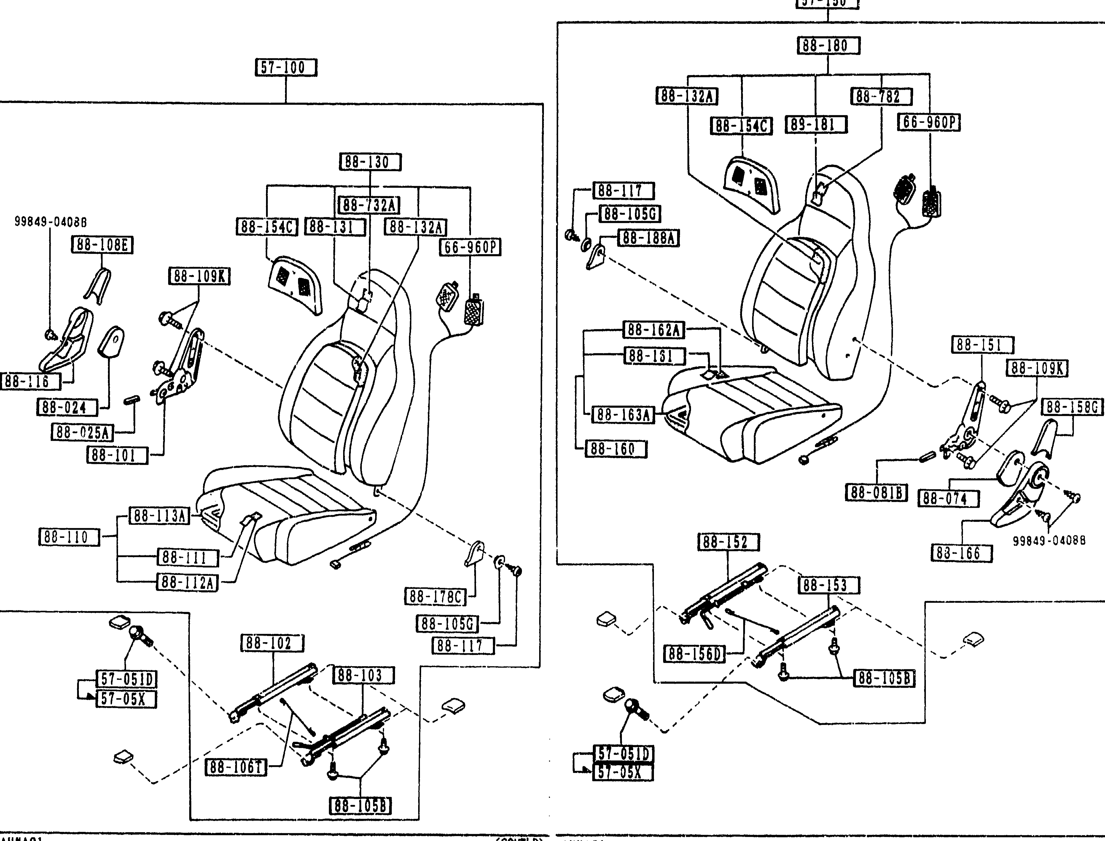
SEATS
2-D10Full-page two-panel exploded view of group 5700 (SEATS) — illustration consists of 2 pages, this page labelled (1/2) on the left side and (2/2) on the right side. Left panel shows the seat (R) (57-100) with seatback frame, headrest assembly (88-30, 88-732A, 88-32A), headrest stay/pad (88-54C, 88-31), cushion frame (88-108E, 88-109K, 88-110, 88-111, 88-112A, 88-113A, 88-178C, 88-105G), reclining hinge bracket (88-024, 88-015A, 88-101, 88-116), seat back catch (88-117), tilt lever rail mounts (57-051D, 57-05X), slide rails (88-102, 88-103, 88-106T, 88-105B), warning switch (66-960P), and tapping screws (99849-04088). Right panel shows the seat (L) — mirror image — (57-150) with seatback (88-180, 88-32A, 88-54C, 88-781, 88-782), headrest catch (66-960P), back side support (88-186A), and identical reclining hinge / slider / cushion family on the left side of that panel (88-151, 88-152, 88-153, 88-156D, 88-162A, 88-163A, 88-160, 88-105G, 88-105B, 88-058C, 88-074, 88-081B, 88-166, 88-109K), with tilt-stay brackets (57-051D, 57-05X) and bolts (99849-04088).
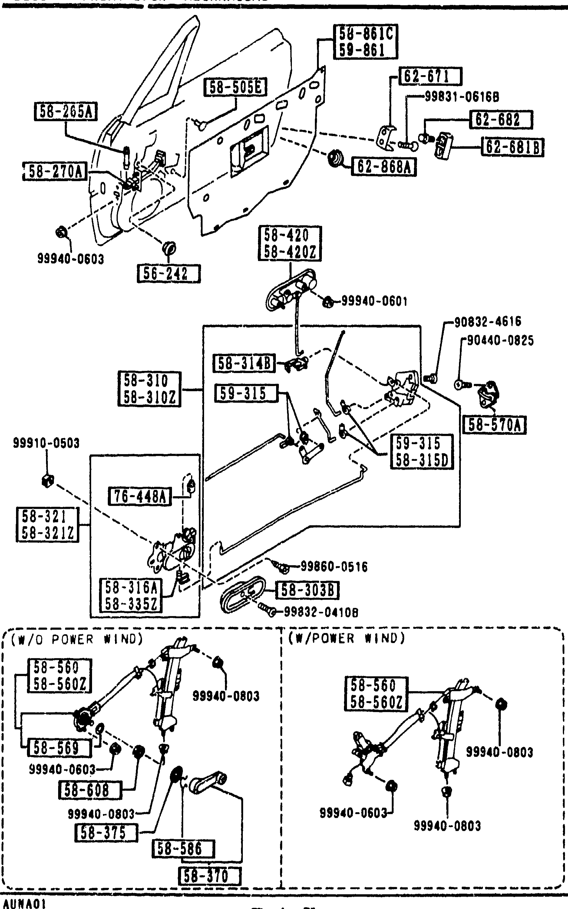
FRONT DOOR MECHANISMS
2-D11Exploded view of front door mechanisms (group 5830). Shows the door inner panel with attachment of regulator, latch, lock cylinder, inside/outside handles, striker and related rods. Bottom-left inset shows two regulator sub-assembly variants labelled 'W/O POWER WIND' and 'W POWER WIND'. Numerous balloon callouts reference part-number boxes (e.g. 58-861C/59-861, 58-505E, 58-205A, 58-270A, 62-671, 99831-0616B, 62-682, 62-868A, 62-681B, 58-375, 58-420, 99940-0603, 56-242, 58-310, 58-314B, 58-310Z, 58-3102, 58-315, 99940-0601, 90832-4616, 90440-0825, 58-420Z, 59-315, 58-315D, 58-570A, 99910-0503, 58-321, 58-3212, 76-448A, 58-3059, 99860-0516, 99832-0410B, 58-505, 58-560Z, 58-569, 58-586, 58-5602, 99940-0803, 58-608, 58-375, 58-370).
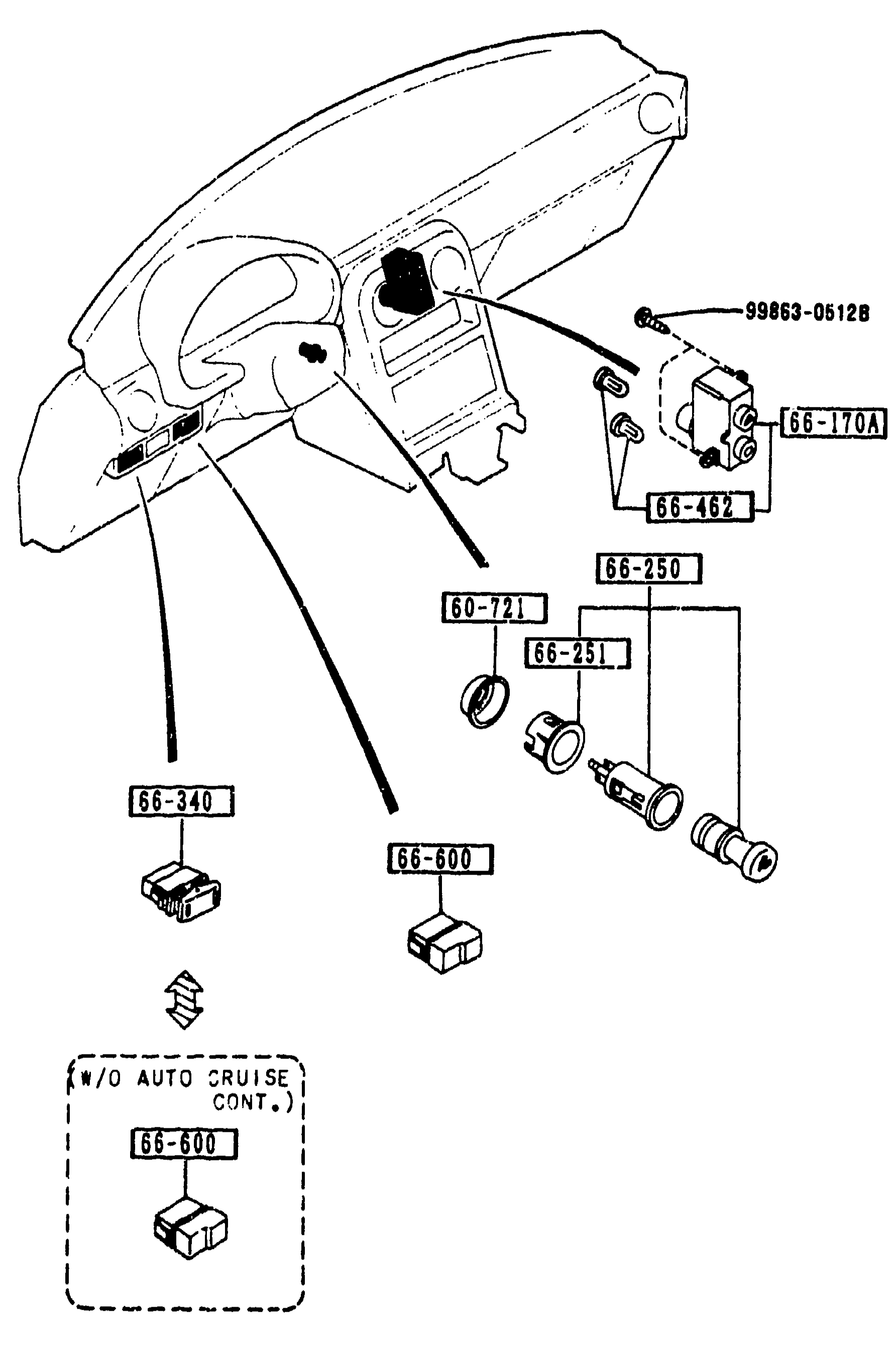
DASHBOARD SWITCHES
2-D14Exploded view of dashboard switches for MX-5 NA. Shows the dashboard panel with various switches and their balloon-callout numbers. Main view shows dashboard with switches 60-721 (PROTECTOR), 66-170A (SWITCH(R),CLUSTER), 66-250 (LIGHTER,CIGAR), 66-251 (RING,ILLUMINATION), 66-340 (SWITCH,MAIN), 66-462 (BULB'B',SWITCH-RR DEFOGER), 66-600 (COVER,HOLE), and fastener 99863-0512B. A separate inset diagram (W/O AUTO CRUISE CONT.) shows part 66-600 alone for non-cruise-control variant.
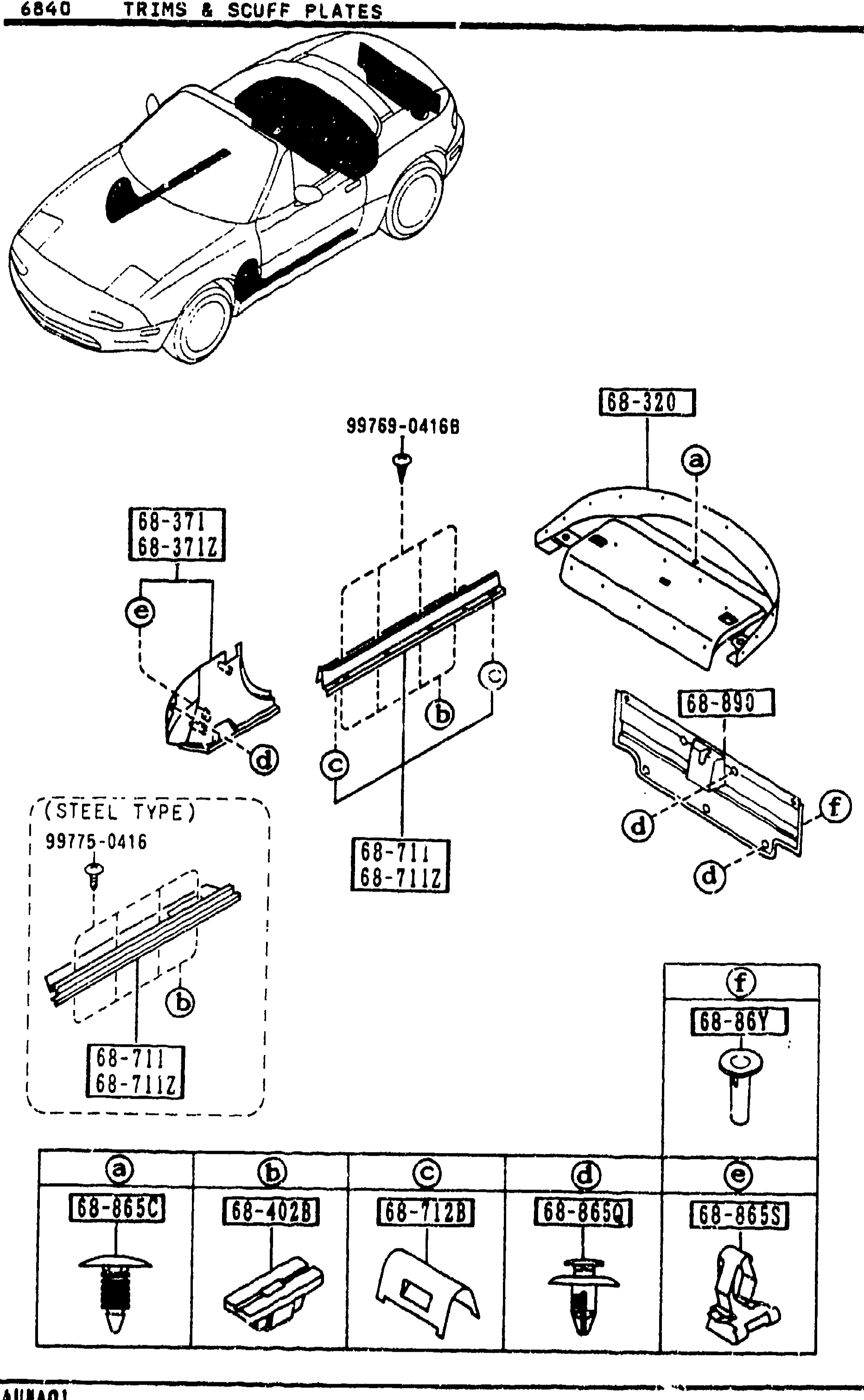
6840 TRIMS & SCUFF PLATES (continued)
2-D16Same exploded view as page 2-C16, repeated here to provide additional callouts (clip trim 68-865S, trunk-end trim 68-890). The illustration shows the MX-5 isometric view at top, rear package tray (68-320), front-side trims (68-371 / 68-371Z), scuff plates (68-711 / 68-711Z) in plastic and STEEL TYPE variants, trim 68-890, cap 68-86Y, and the same five-fastener detail row at the bottom (a)68-865C, (b)68-A0Z3, (c)68-712B, (d)68-865K, (e)68-865S.
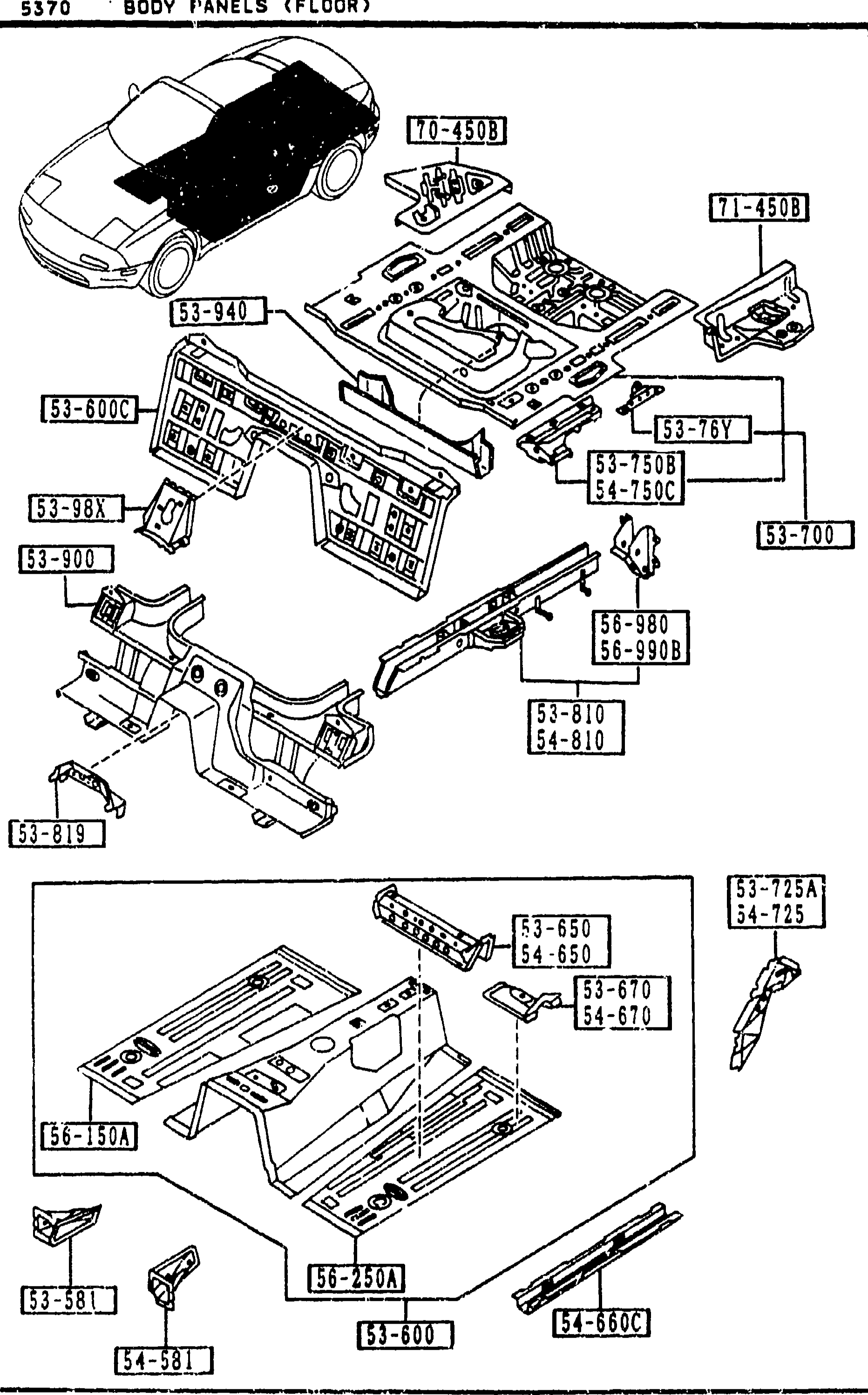
BODY PANELS (FLOOR)
2-D8Continuation of the body-floor exploded view. Top sub-diagram shows the floor structure from a front-isometric perspective with balloons including 53-940 (member no.4 cross), 53-98X (gusset front floor pan), 54-981 (junction L frt floor), 54-650 (member no.2 L cross floor), 54-680 (frame, front-frt floor pan), 54-670 (brkt L seat F floor pan), 54-725 (gusset L C floor pan), 54-7508 (plate L side-rear F floor), 54-810 (frame L rear side). Bottom-left sub-diagram shows the floor pan with callouts 53-725A, 54-725, 54-680, 54-6804, 54-810D.
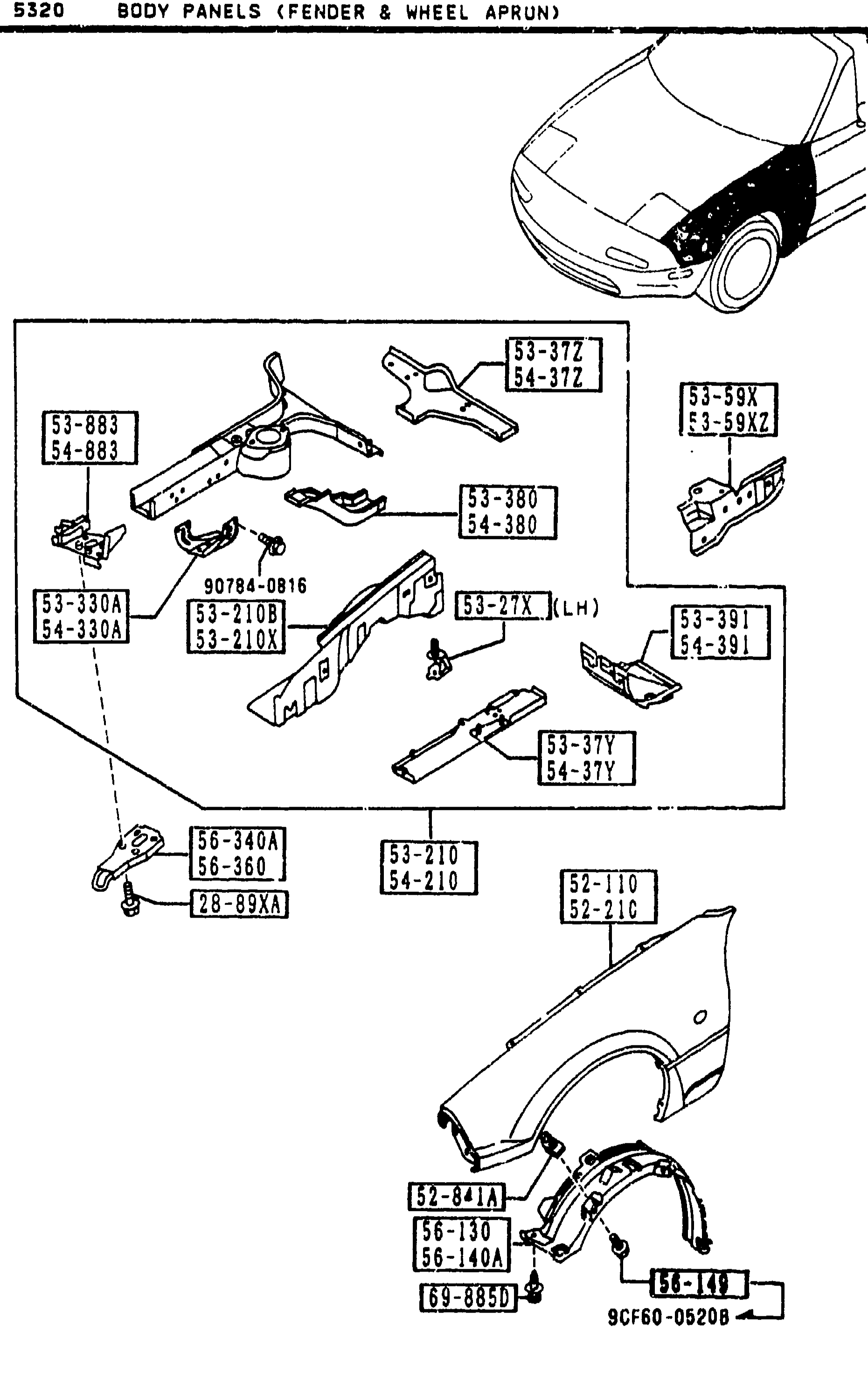
BODY PANELS (FENDER & WHEEL APRON)
2-E 7Front body panels — fender & wheel apron exploded view. Top: 3/4 perspective sketch of the front of the car. Middle: exploded view of the inner wheel apron / front frame assembly with wheel apron panels [53-210B], front-rail frame parts [53-37Y, 53-37Z], stabilizer bracket [53-330A], air-cleaner / wheel-apron bracket [53-27X], fender mounting brackets [53-883, 54-883], frame member [53-380, 54-380], plus various clips and bolts. Bottom: outer fender [52-110/52-210], inner fender liner [52-841A], stone guard [56-130, 56-140A], with mud-flap-area trim parts.
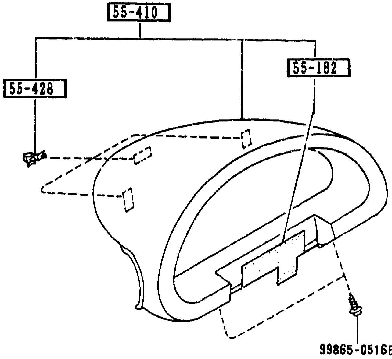
METER HOOD
2-E 9Exploded view of the MX-5 instrument cluster meter hood. Centre artwork shows the moulded meter hood with three balloon callouts: 55-410 (HOOD, METER — the moulding itself), 55-182 (RUBBER, BLIND — a small rubber blind insert at the top), and 55-428 (SPRING, METER HOOD — a clip at the lower-left of the hood). A 99865-0516B fastener is shown at the bottom-right with a leader pointing into the hood underside.
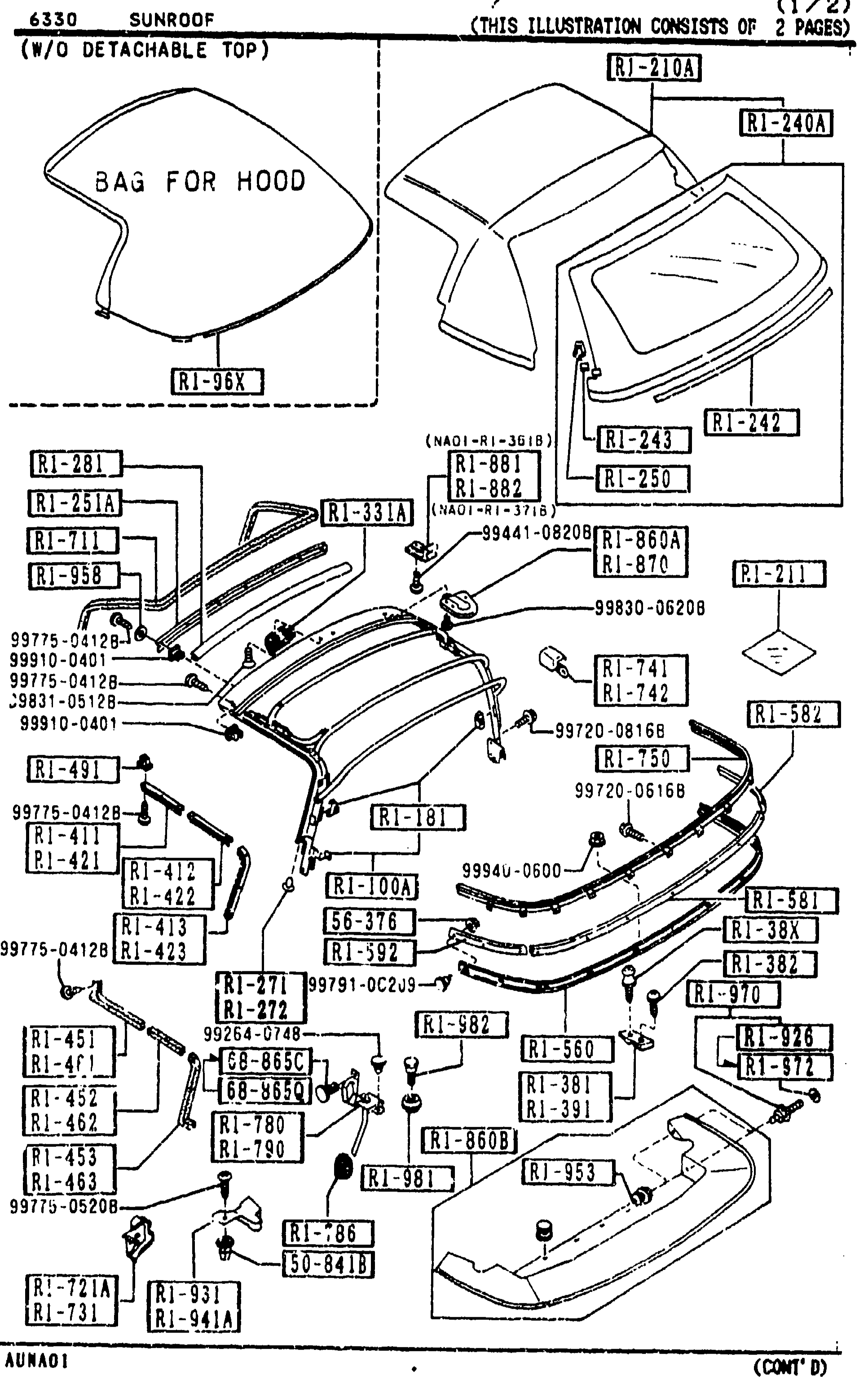
6330 SUNROOF (W/O DETACHABLE TOP) — (1/2)
2-E13Exploded view of the soft-top (W/O detachable top) assembly: bag for hood at top, then the soft-top fabric, frame, hooks, clips, plates, retainers and rain rail laid out with balloon callouts referencing part-number labels (e.g. R1-100A, R1-100C, R1-100D, R1-181, R1-210A, R1-210B, R1-243, R1-246A, R1-247, R1-247A, R1-248A, R1-251, R1-258A, R1-272, R1-282, R1-381, R1-301, R1-411, R1-417, R1-421, R1-422, R1-423, R1-435, R1-453, R1-461, R1-462, R1-463, R1-471, R1-490, R1-501, R1-661, R1-700, R1-731, R1-731B, R1-741, R1-790, R1-810, R1-832, R1-845, R1-861, R1-862, R1-865A, R1-870, R1-895, R1-941A). Many small fastener callouts (59770-xxxx, 59941-08208, 59650-08208, 99830-06208, 59920-06168, 59940-0600, 59930-06208, 9994x-0500, 99774-04128, 99775-04128) populate the diagram. Marked '(CONT'D)' bottom-right.
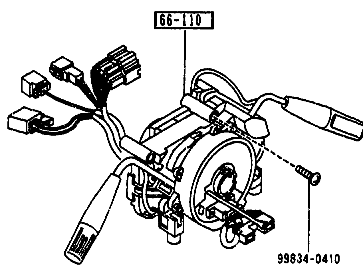
COMBINATION SWITCH
2-E14Exploded view of combination switch assembly (steering column-mounted turn signal, wiper, headlamp stalks). Shows the combination switch (66-110) at the center of a steering-column harness with multiple connector plugs branching off, plus a mounting screw (99834-0410).
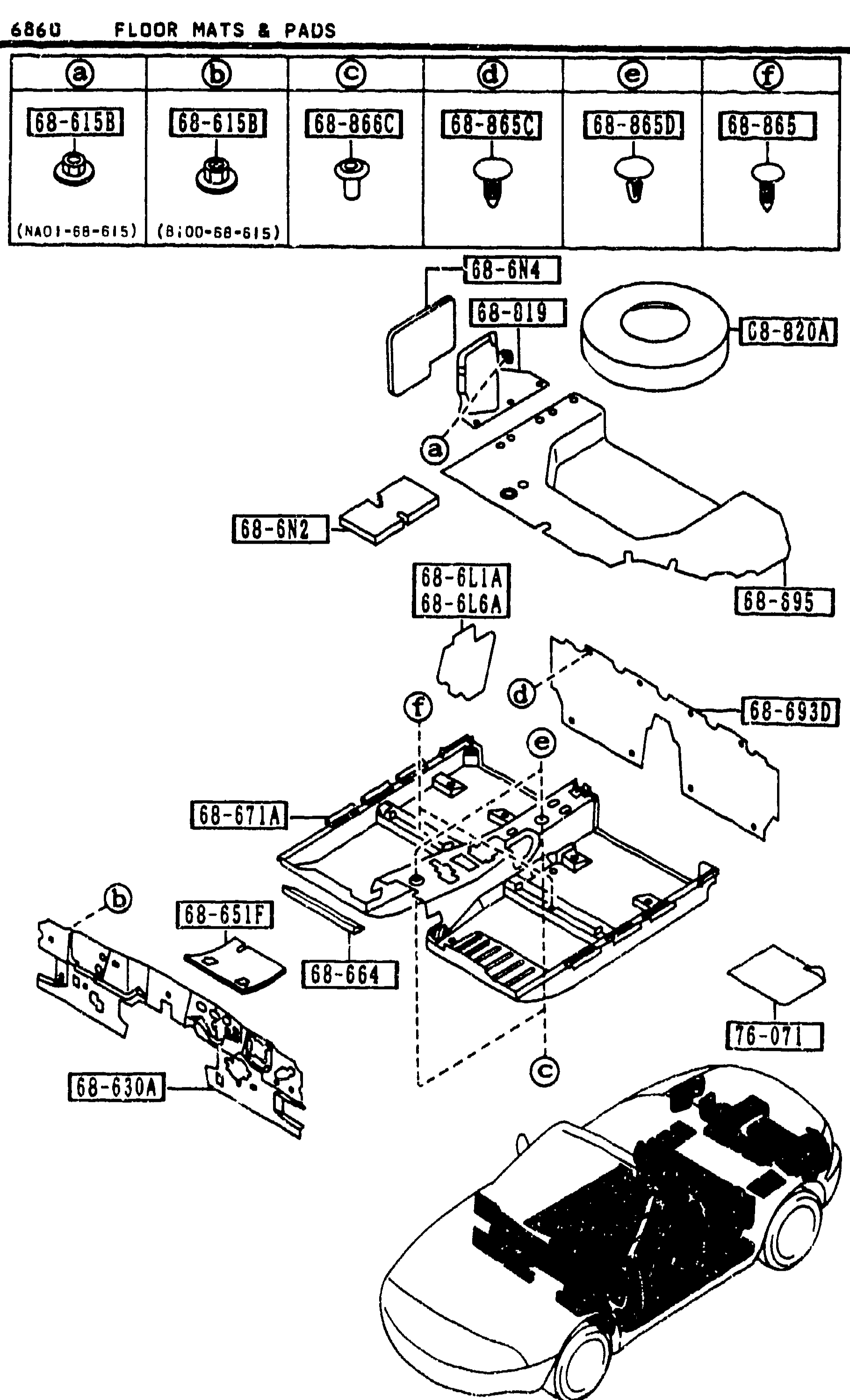
6860 FLOOR MATS & PADS
2-E16Exploded view of MX-5 floor interior: cabin floor pan with rear bulkhead and tunnel, showing locations of insulators (68-6N2 rear floor, 68-6N4 rear fender, 68-630A dashboard), floor pads (68-651F), floor mat (68-671A), trunk-room mat (68-695), and rear-end mat (68-693D). Top row of six small fastener illustrations (a)68-615B, (b)68-615B, (c)68-866C, (d)68-865C, (e)68-865D, (f)68-865 keyed to letter callouts on the larger view. Bottom-right small isometric MX-5 vehicle drawing shows the interior context with the floor mat installed.
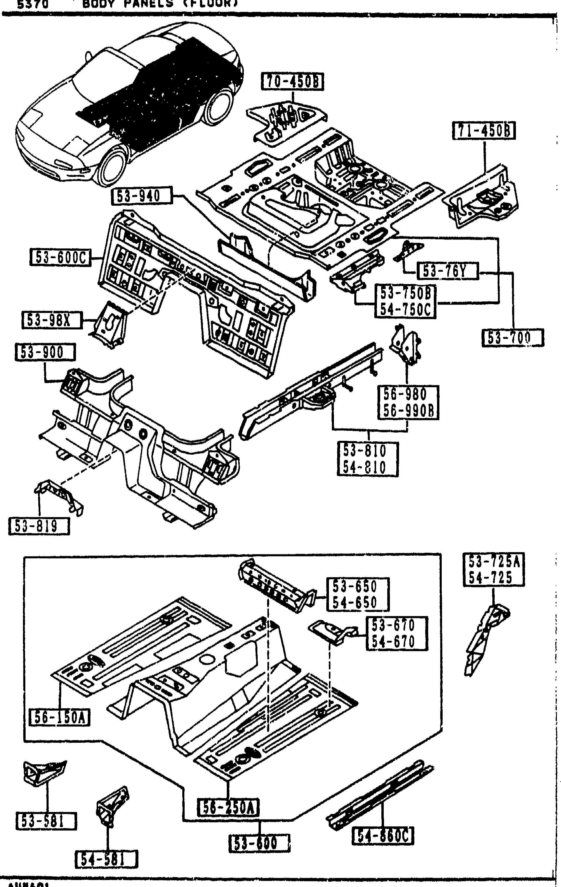
BODY PANELS (FLOOR)
2-E8Continuation of the body-floor exploded view (3M). Top sub-diagram shows the floor structure from front-isometric with callouts including 70-450B, 71-450B (panel R/L floor side), 53-940, 53-600C, 53-38X, 53-800, 53-7508, 53-7600, 53-76Y, 54-750C, 53-700, 56-980, 56-990B, 53-810, 54-810. Bottom-left sub-diagram shows the floor pan from above with callouts 53-725A, 54-725, 53-650, 54-650, 53-670, 54-670, 56-150A, 53-580, 56-250A, 53-800, 54-680A.
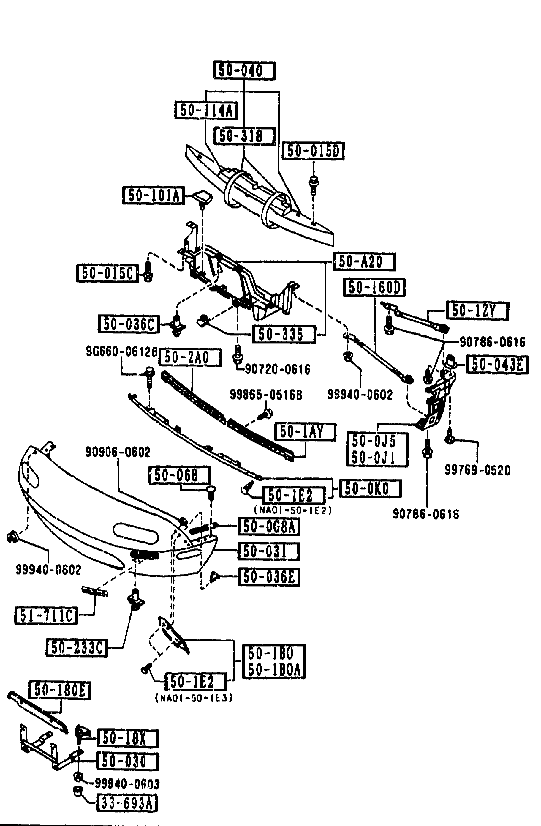
FRONT BUMPER (5000)
2-F 5Exploded view of FRONT BUMPER assembly (group 5000). Shows the front bumper cover (50-221-style cover at bottom-left), bumper reinforcement / energy absorber bar at top with brackets, side stays and license-plate bracket. Balloon callouts label each part by short part number (50-XXX) with reference fasteners (90xxx, 99xxx, 9G660-xxxx). Multiple bracket/stay/spacer subassemblies are shown exploded around the central reinforcement.
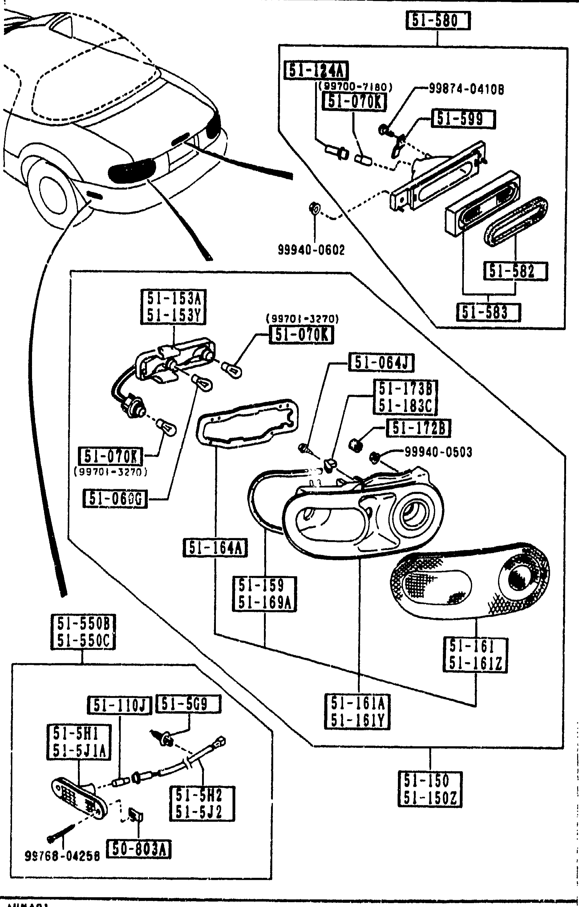
REAR COMBINATION LAMPS
2-F 6Exploded view of MX-5 rear combination lamp area. Top: rear-quarter vehicle silhouette showing the high-mount stop lamp (51-580/51-582/51-583) mounted on the deck lid. Middle: main rear combination lamp assembly with lens/body 51-164A, sockets 51-153A/Y, 51-173B, 51-183C, 51-172B, harness 51-070K (cross-ref 99701-3270), 51-060G, 51-159, 51-169A, 51-161A/Y, 51-150/51-150Z. Bottom-left: side-turn rear assembly 51-110J/51-5C9 with 51-5H1/51-5J1A, 51-5H2/51-5J2, 50-803A. Fasteners 99874-0410B, 99940-0602, 99940-0503, 99768-0425B, 51-064J, 51-070K, 51-124A, 51-599, 51-550B/51-550C.
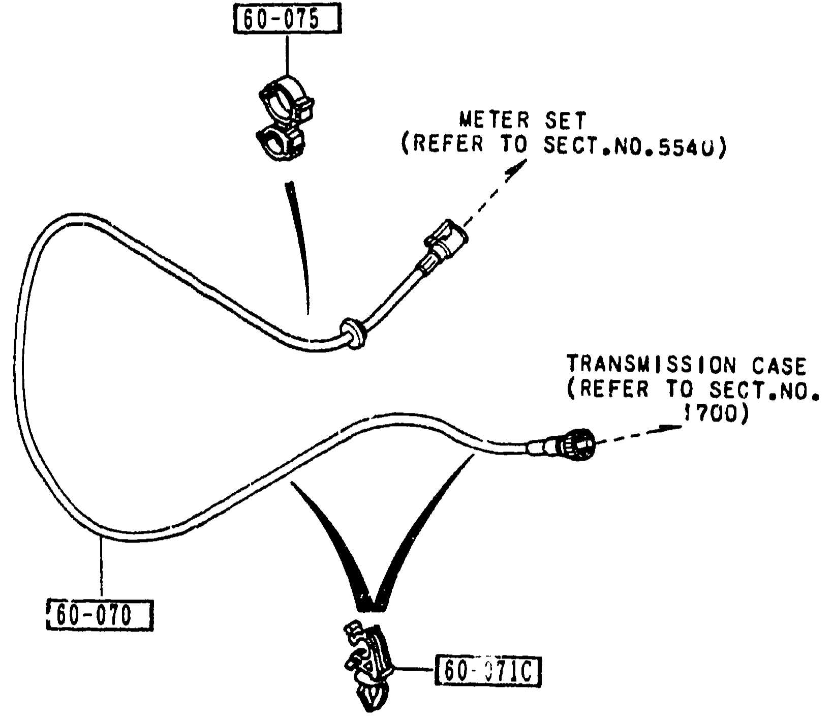
SPEEDOMETER CABLE
2-F 9Exploded view of the MX-5 speedometer cable assembly. A serpentine speedometer cable (60-070) is shown with one end labelled 'METER SET (REFER TO SECT.NO. 5540)' (upper-right meter-side fitting) and the other end labelled 'TRANSMISSION CASE (REFER TO SECT.NO. 1700)' (lower-right transmission-side fitting). Two clip parts are called out: 60-075 (small spring-clip near the meter end) and 60-071C (P-clip at the lower-centre near the transmission end).
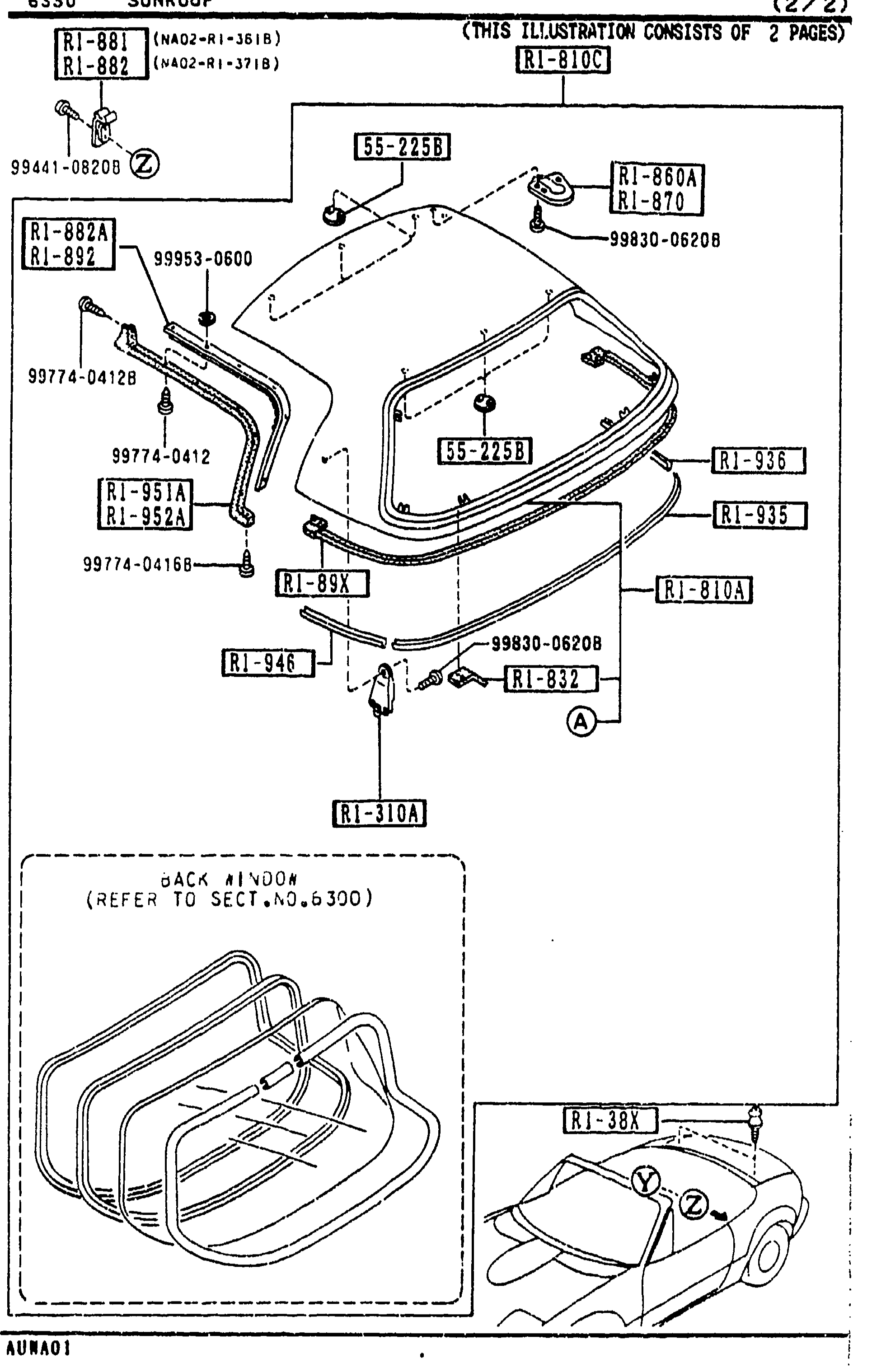
6330 SUNROOF (W/O DETACHABLE TOP) — (2/2)
2-F13Continuation exploded view (2/2) of the W/O detachable-top sunroof: rear-deck soft-top trim, welts, hooks, retainers, plates, locks. Visible callouts: R1-881, R1-882, R1-810C, R1-860A, R1-870, R1-882A, R1-892, R1-951A, R1-952A, R1-89X, R1-936, R1-935, R1-946, R1-810A, R1-832, R1-310A, R1-381, R1-38X, R1-741. Fasteners: SS-225B, SS-225B (lower), 99441-08208, 99953-0600, 99830-06208, 99774-04128, 99774-04168. Marked '(Z)' at top-left and '(A)' / '(Y)' indicator points. Lower inset shows BACK WINDOW (REFER TO SECT.NO.6330) and a car silhouette with body-side hint.
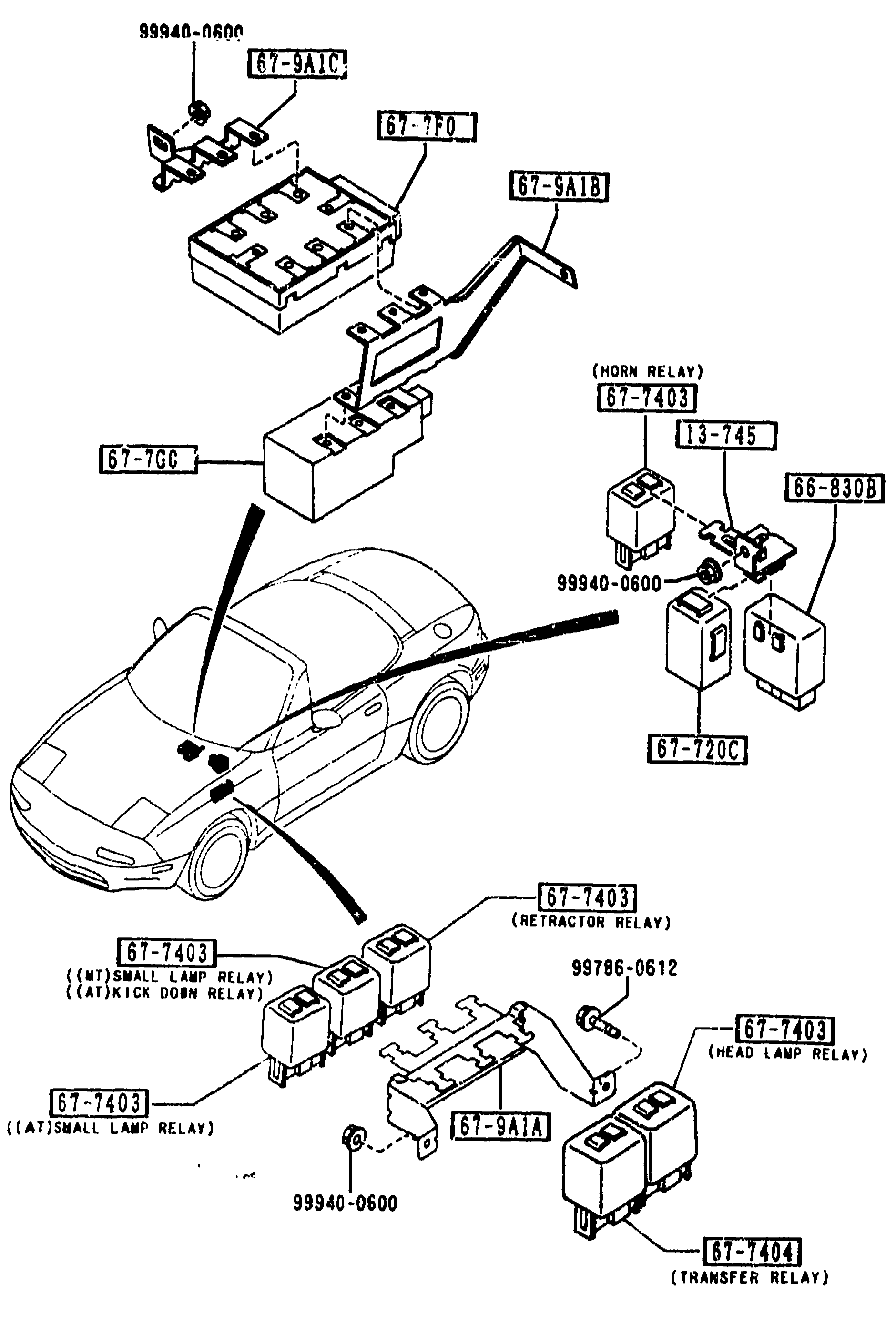
RELAYS & UNIT (BODY)
2-F14Exploded view of body relays & unit for MX-5 NA. Top-left shows the relay box with relays 13-745, 87-9A1C, 67-7F0, 87-9A1B (mounted on a bracket) connected to the vehicle by harness. Vehicle silhouette shows mounting locations for HORN RELAY (67-7GC), HEAD LAMP RELAY (67-7403), SMALL LAMP RELAY (MT/AT), KICK DOWN RELAY (AT), TRANSFER RELAY (67-7404), RETRACTOR RELAY, TIMER & BUZZER (67-720C), and DIAGNOSIS POWER UNIT (67-9A1A/9A1B). Includes fasteners 99940-0600, 99786-0612, 99940-0500.
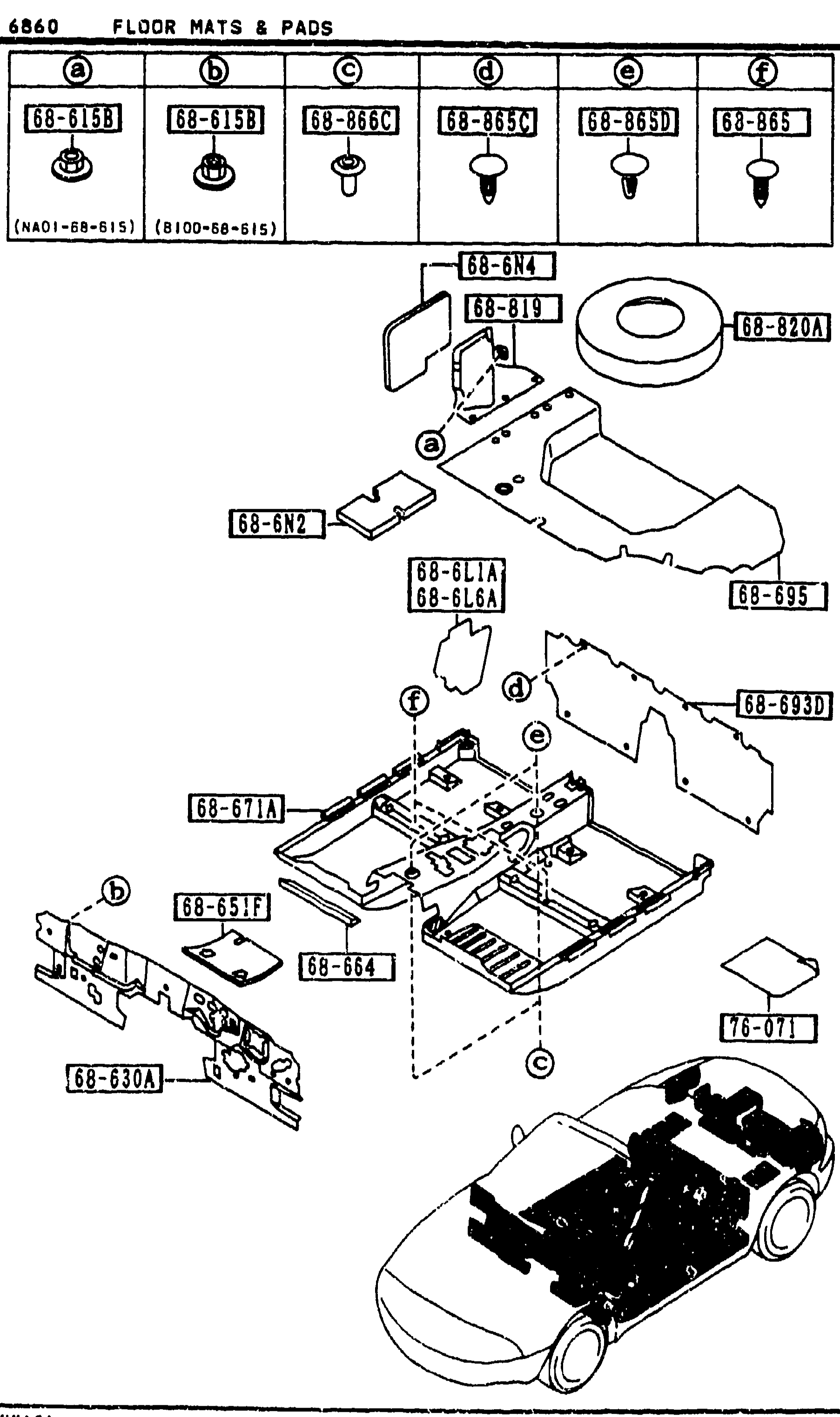
6860 FLOOR MATS & PADS (CONT'D)
2-F16Exploded parts diagram of MX-5 floor mats, pads, fasteners, covers and silencers. Balloon callouts show parts 68-615B (a), 68-619 (a), 68-820A, 68-6N4, 68-6N2, 68-6LIA/68-6L6A, 68-695, 68-693A, 68-617A (f), 68-651F (b), 68-664, 68-630A, 76-071 (c). Lower-right inset shows a vehicle silhouette with locations (a), (b), (c). Catalog top references parts 68-615B (a), 68-615B (b), 68-866C (c), 68-865C (d), 68-865D (e), 68-865 (f).
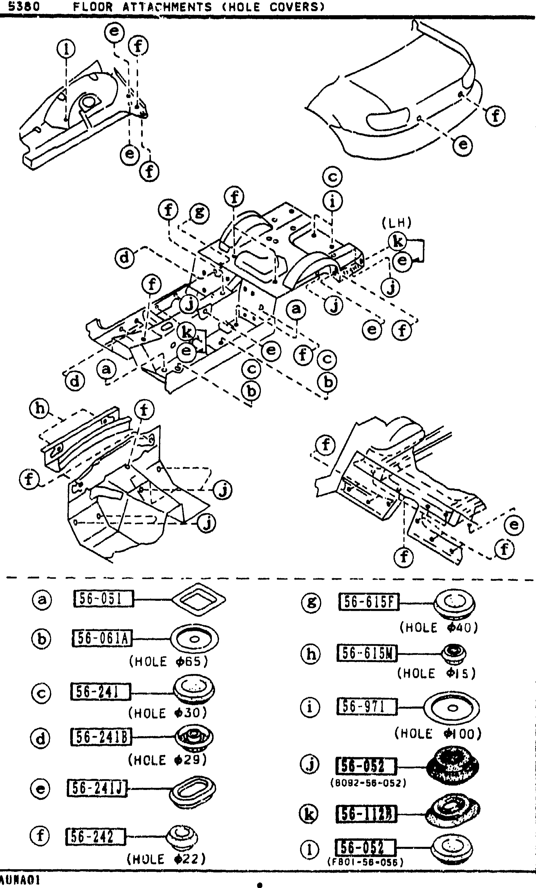
FLOOR ATTACHMENTS (HOLE COVERS)
2-F8Floor-attachments exploded view: three sub-diagrams of the underbody showing locations of hole-cover plugs and drain plugs labelled with letters a–l. Top sub-diagram shows the front engine/firewall area with letters a, b, c, d, e, f. Middle sub-diagram shows the underbody with letters c, d, e, f, b, g, h, i, j, k. Bottom sub-diagram shows the rear floor pan with letters a, b, c, e, f. Bottom-left legend strip shows the individual cover/plug parts: (a) 56-051, (b) 56-061A (HOLE φ65), (c) 56-241 (HOLE φ30), (d) 56-241B (HOLE φ100), (e) 56-241J (HOLE φ29), (f) 56-242 (HOLE φ22), (g) 56-615F (HOLE φ40), (h) 56-615M (HOLE φ15), (i) 56-971 (HOLE φ50), (j) 54-052 (8092-56-052), (k) 56-112A, (l) 54-052 (F801-56-055).
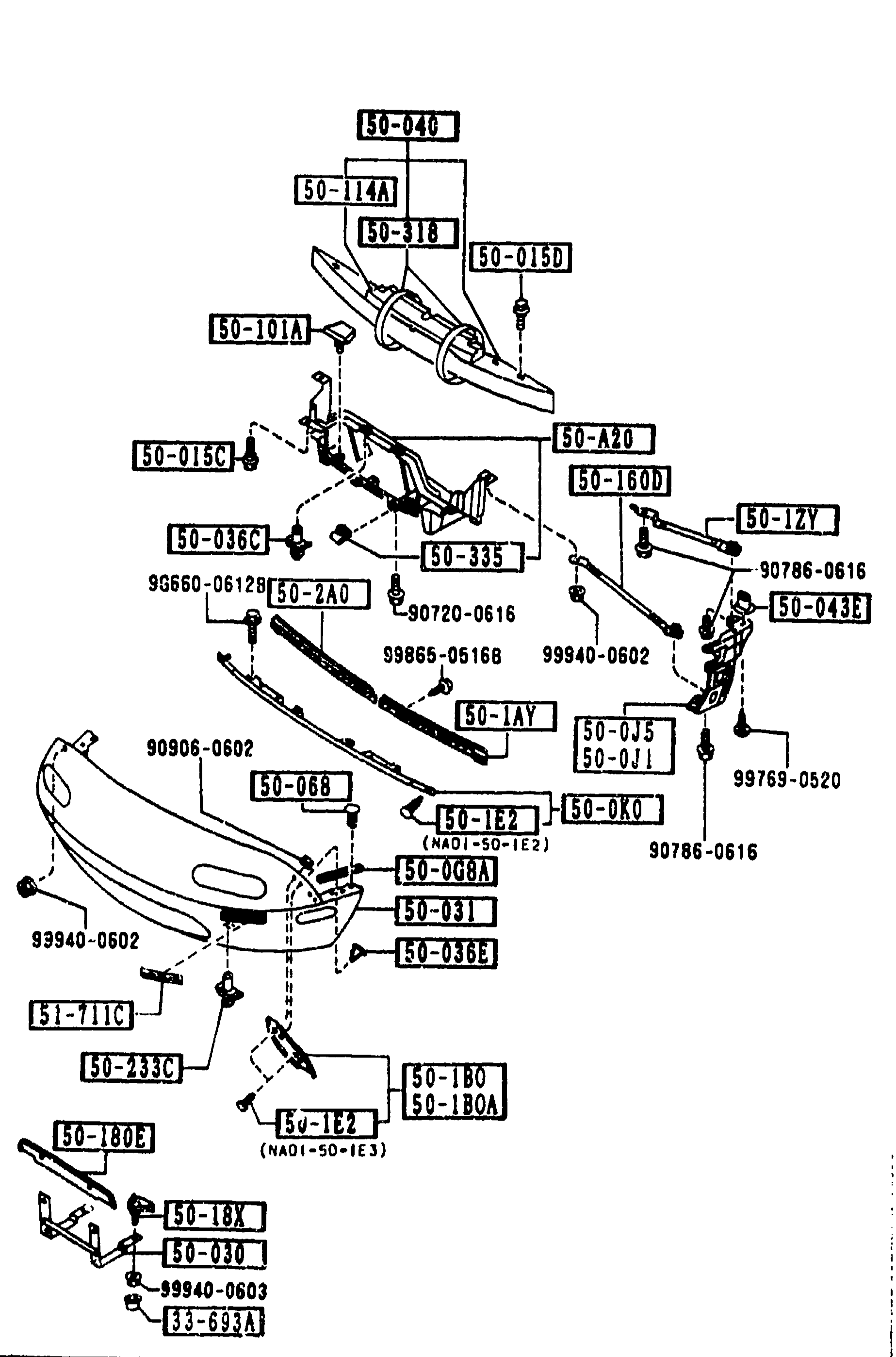
FRONT BUMPER (5000) — continued
2-G 5Repeat of FRONT BUMPER (5000) exploded view from page 2-F 5, showing the same bumper cover, reinforcement, brackets and stays so the continued parts list on the right side of this page can still reference balloon callouts. Identical layout to previous page; no new parts added to the drawing itself.
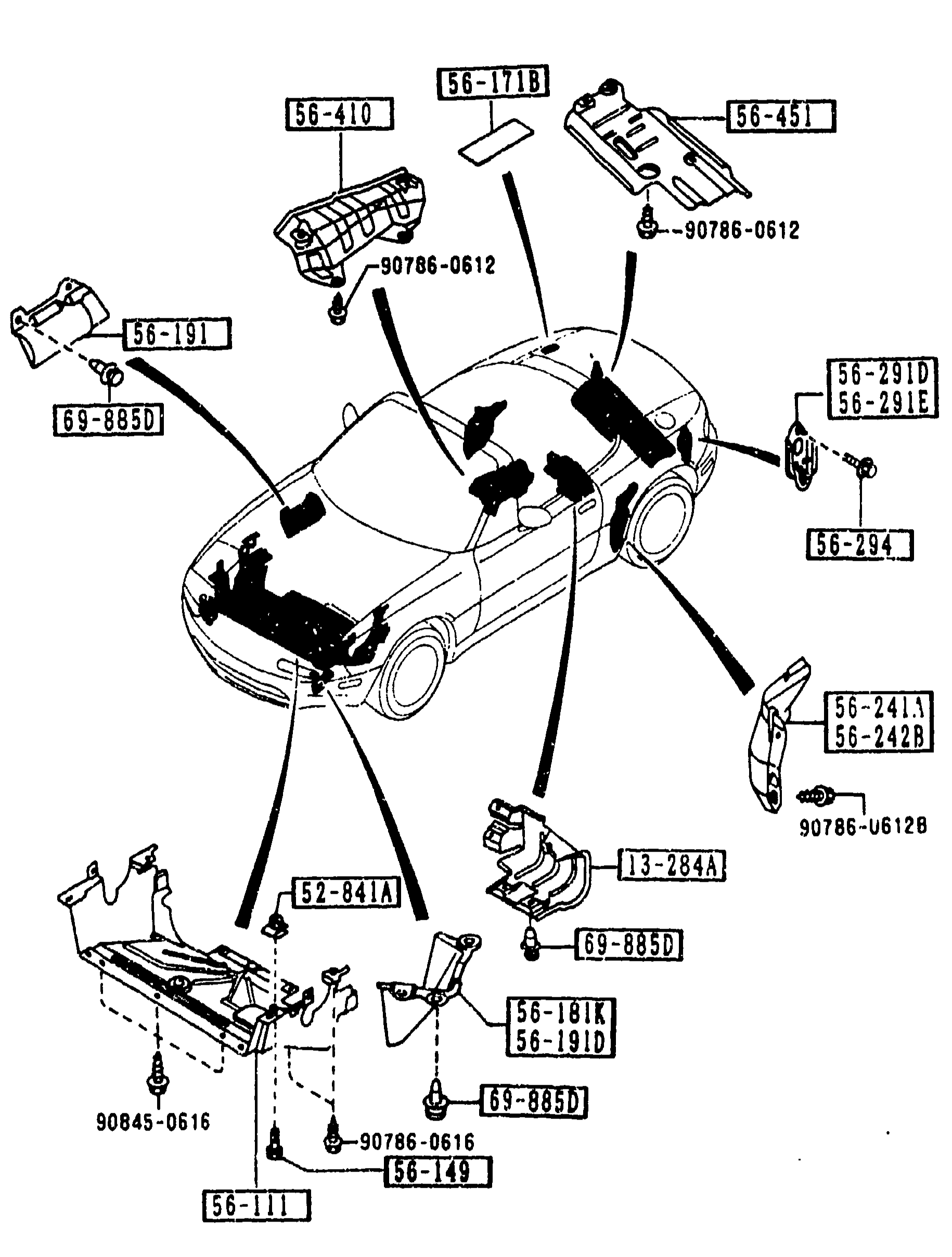
FLOOR ATTACHMENTS
2-G 8Exploded view of the MX-5 (NA) underbody/floor showing the body shell from a left-front three-quarter perspective with floor and fender protector attachments exploded around it. Balloon callouts label individual parts (covers, shields, screws, clips, protectors) and small inset detail views of clip-on shields and brackets. Fasteners are shown with their part numbers (e.g. 90786-0612, 90786-U612B, 90845-0616).
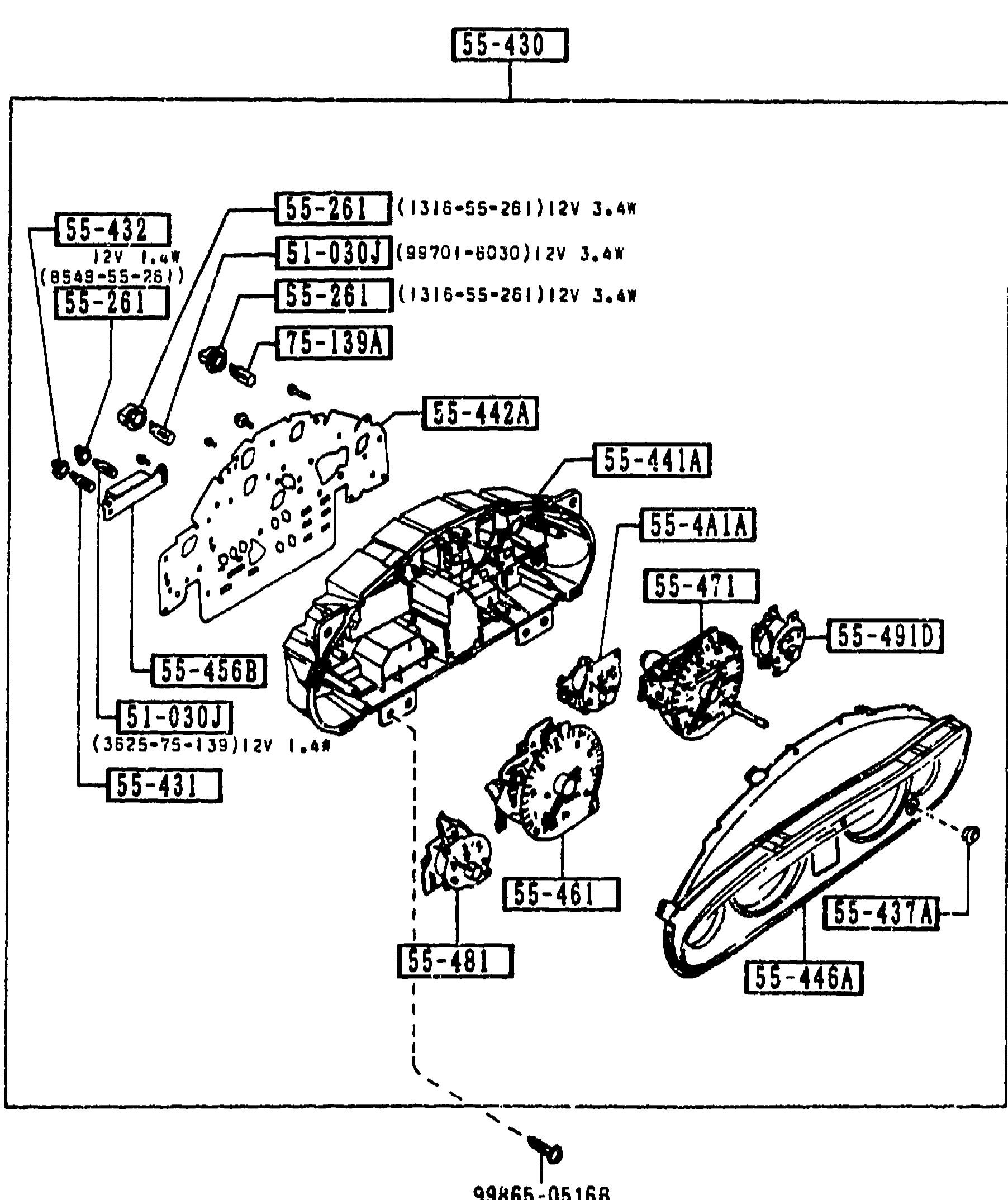
METER COMPONENTS
2-G 9Exploded view of the MX-5 instrument cluster (meter set). The cluster bezel and lens (55-430) lift off to reveal the printed-circuit face plate with speedometer/tachometer/fuel/temp gauges and the auxiliary gauges (55-441A meter, 55-441, 55-431 bulb-resister, 55-461). Bulb-and-socket assemblies (51-030J / 55-261 with 12V 1.4W and 12V 3.4W variants) populate sockets around the printed circuit. A 99865-0516B fastener anchors the cluster to the dashboard. Other callouts: 55-432 socket, 55-442A meter, 55-441A case, 55-441C, 55-441A1, 55-468B / 55-471 / 55-491D inserts, 55-481 grommet/case bottom, 75-139A switch/socket, 55-437A grommet-knob.
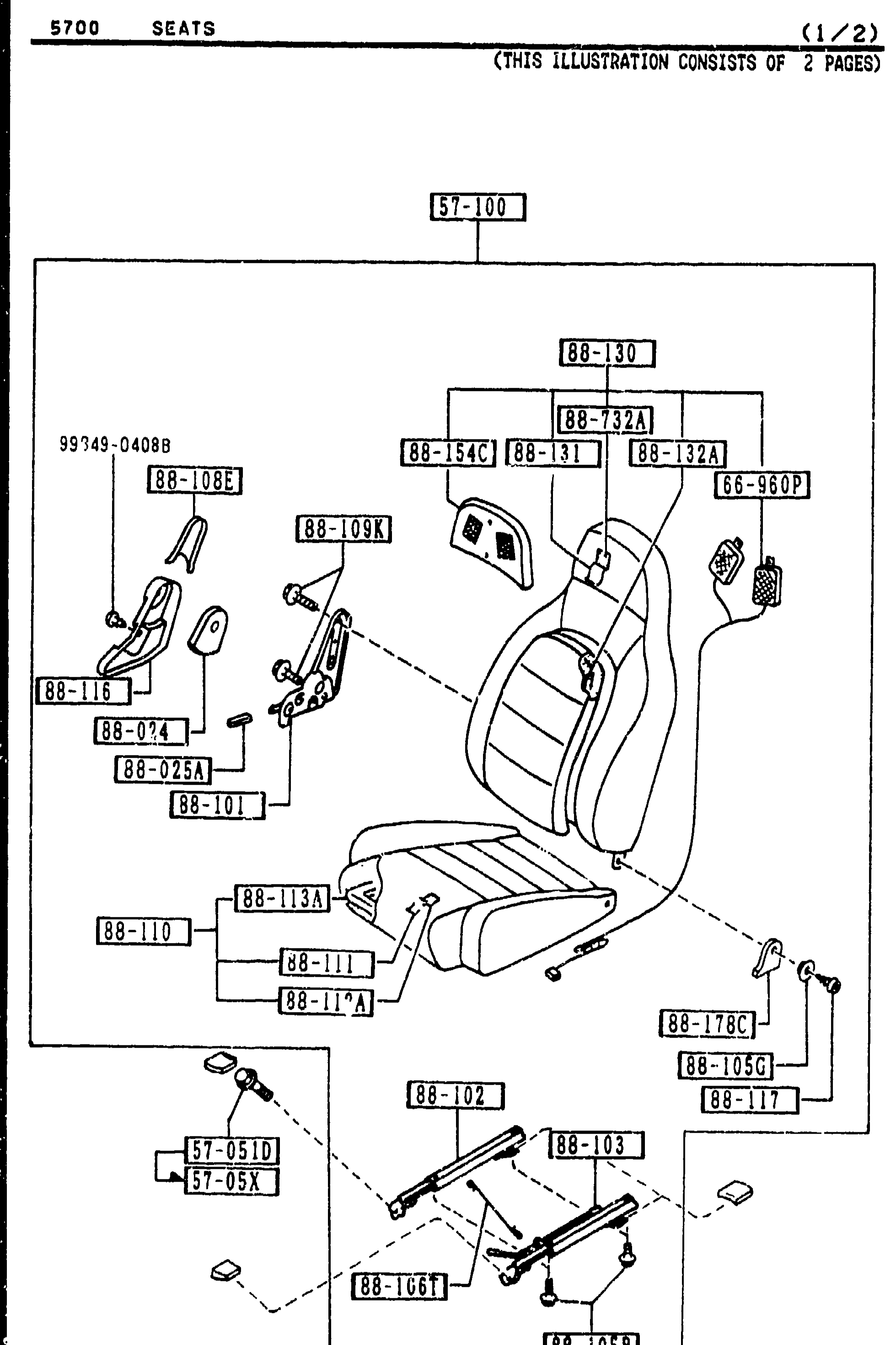
SEATS (1/2)
2-G10Exploded view of front seat assembly (1 of 2). Shows seat back, cushion, headrest, recliner mechanism, slide adjusters and mounting hardware. Numerous balloon callouts identify component part numbers including 88-30 (seat back trim), 88-732A (head restraint), 88-131, 88-32A, 88-54C, 88-181, 66-960P, 88-108E, 88-109K, 99749-04088, 88-116, 88-074, 88-025A, 88-101, 88-113A, 88-110, 88-111, 88-176A, 88-105C, 88-117, 88-102, 88-103, 57-100 (parent assembly), 57-0510, 57-05X (slide assemblies) and 88-106T (wire connect).
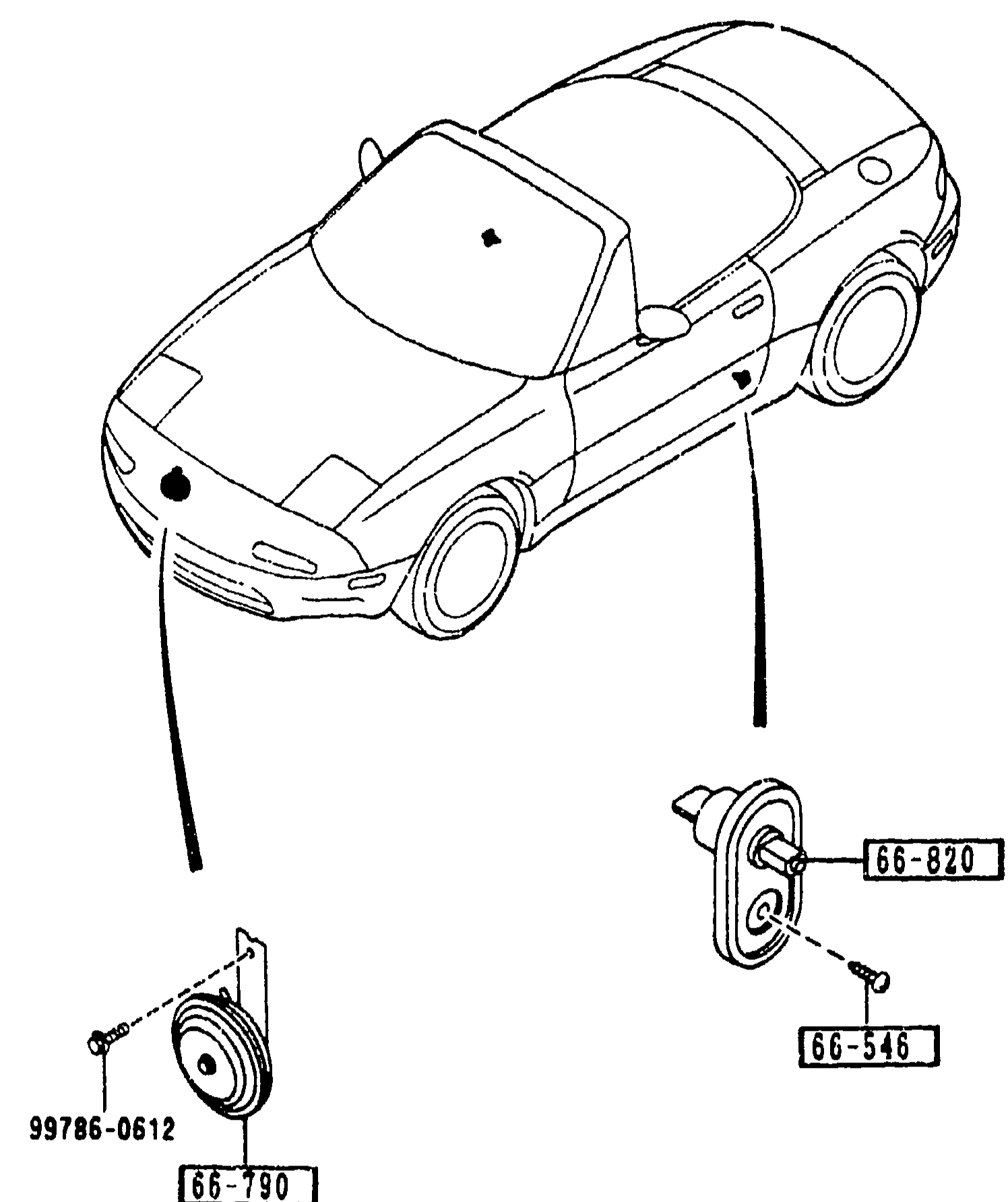
DOOR SWITCH & HORNS
2-G14Exploded view of door switch and horns for MX-5 NA. Shows the convertible MX-5 silhouette (driver-side three-quarter view) with the horn mounted at the front-left of the engine bay (part 66-790, secured by 99786-0612) and the door jamb switch on the driver door (part 66-820, with screw 66-546).
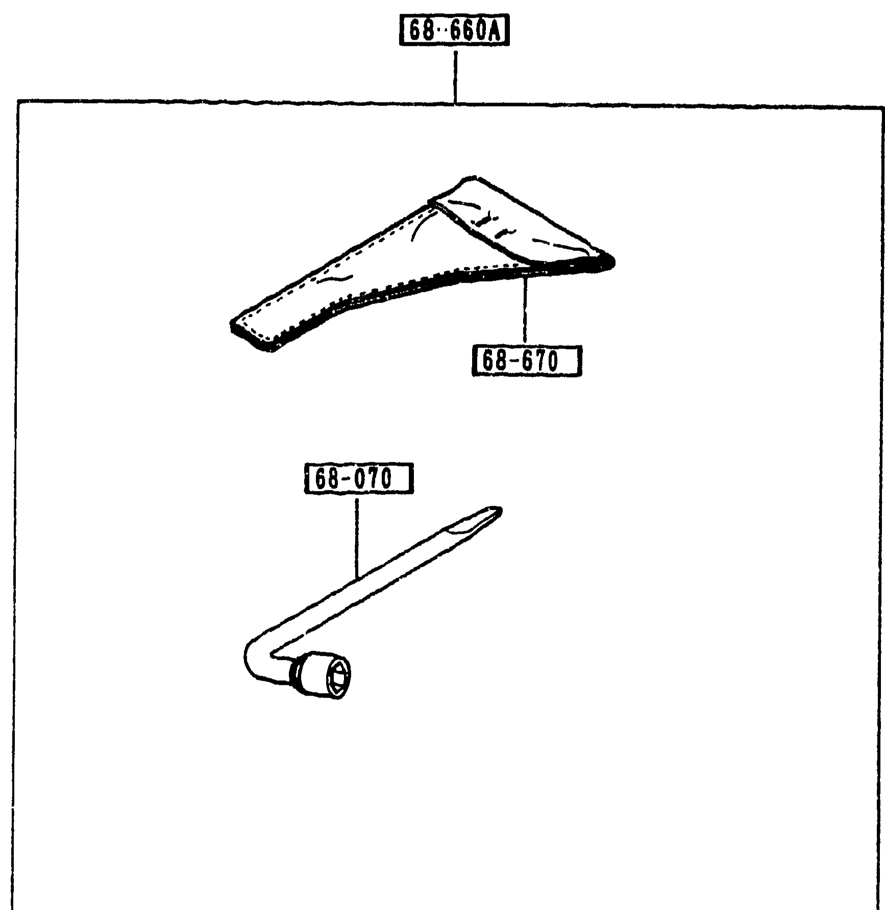
6870 SERVICE TOOLS
2-G16Exploded view of service tools shipped with the vehicle: tool bag (68-660A) at top containing the tool roll (68-670), and the hub-nut wrench (68-070) below. Each balloon callout links to a part-number label.
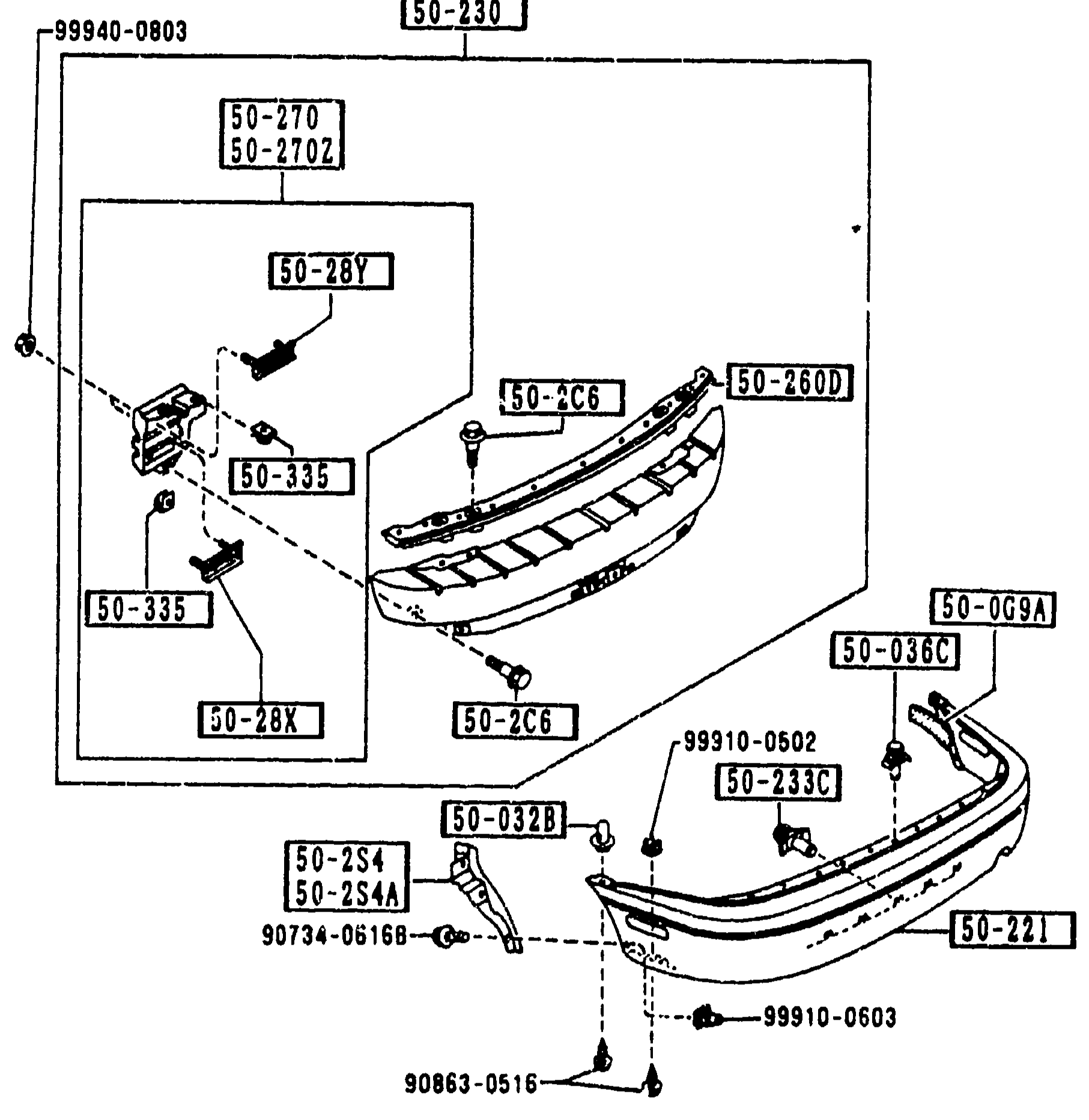
REAR BUMPER (5010)
2-H 5Exploded view of REAR BUMPER assembly (group 5010). Shows the rear bumper cover (50-221), reinforcement bar with mounting brackets (50-230, 50-260D), splash shields R/L (50-2S4, 50-2S4A), bumper stays R/L (50-270, 50-270Z, 50-280A, 50-290A), fasteners and clips. The reinforcement assembly bracket is enclosed in a sub-box.
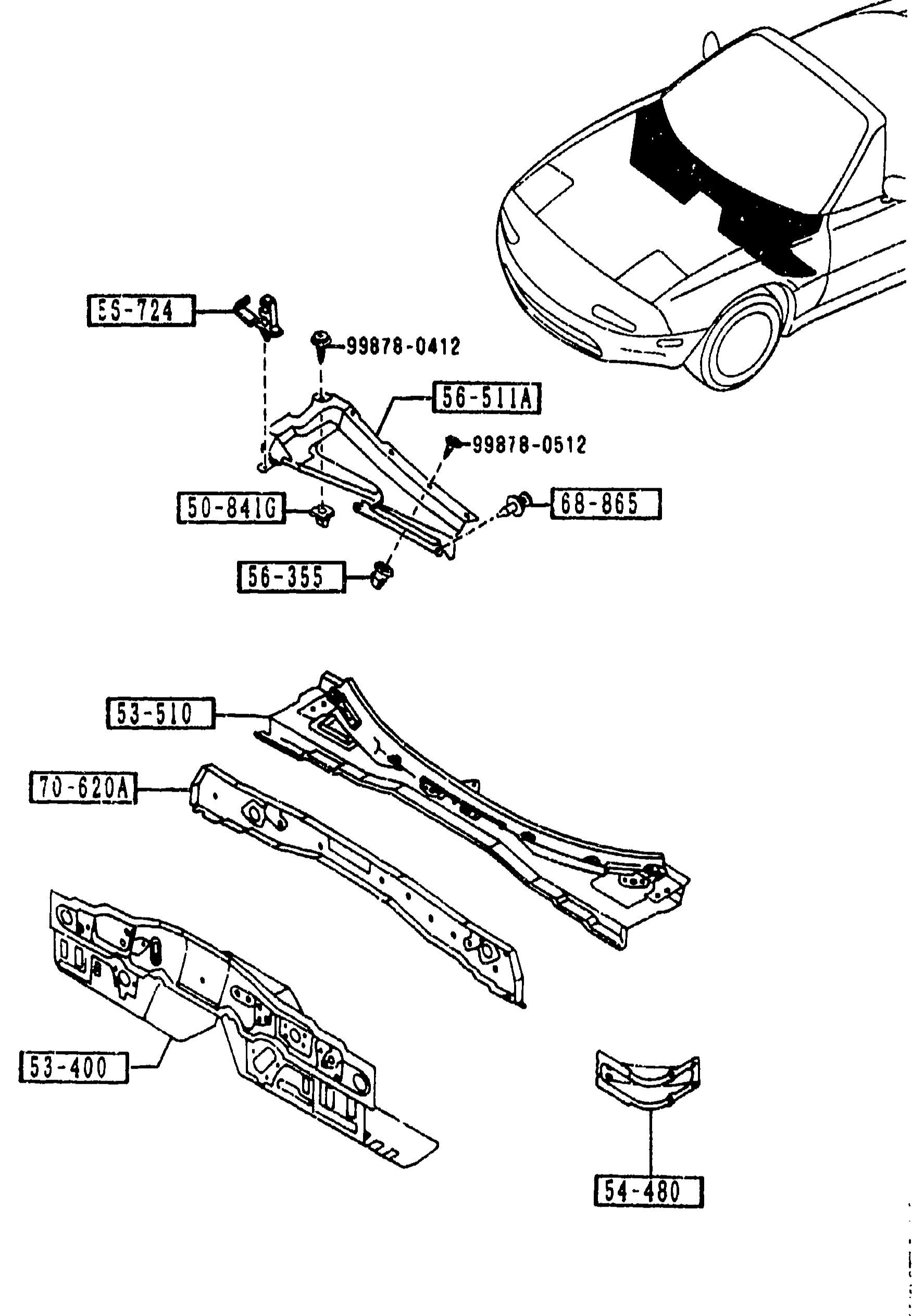
BODY PANELS (DASH & COWL PANEL)
2-H 7Body panels — dash & cowl panel exploded view. Top: 3/4 perspective sketch of the car with cowl & windscreen base shown. Middle/bottom: exploded view of the dash panel assembly: lower dash panel [53-400], upper dash panel [53-510], cowl-front panel [70-620A], dash side-sill junction [54-480], cowl baffle cover [56-511A], wire-bonnet clips [56-724], grommets [50-841G, 30-841G], fasteners [68-865], and various screws/bolts [99878-0412, 99878-0512].
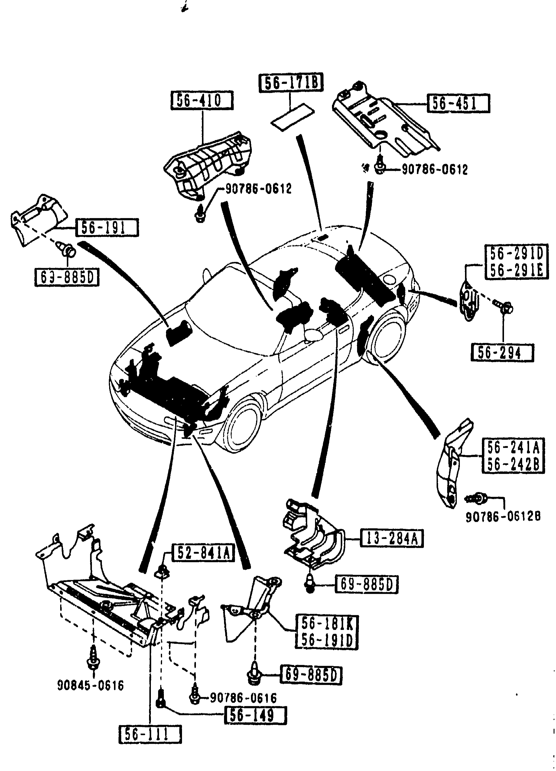
FLOOR ATTACHMENTS
2-H 8Exploded view of the MX-5 (NA) floor and undercar — left-front three-quarter perspective of the body shell with floor attachments exploded around it. Balloon callouts label individual parts (covers, shields, tie-down hooks, fasteners, heat insulators) with inset detail views around the perimeter. Same visual as page-1142 but tagged with the second sub-group of part numbers (-2 M).
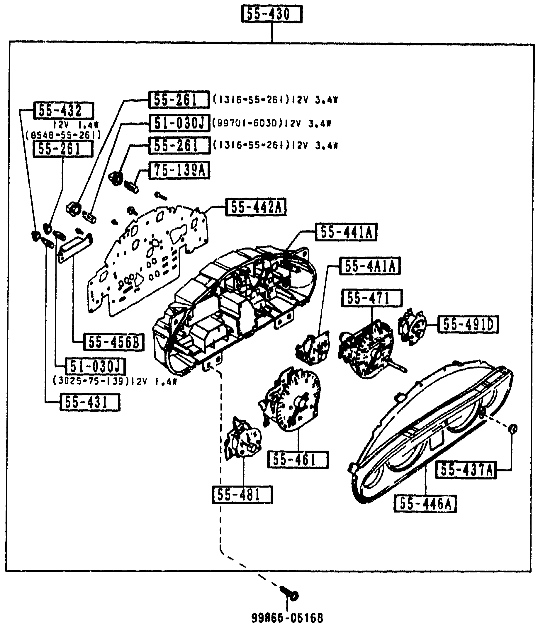
METER COMPONENTS
2-H 9Continuation exploded view of the MX-5 instrument cluster — same artwork as page-1149 with the bezel/lens (55-430) lifted off and the printed-circuit face plate populated with bulb-and-socket sub-assemblies (51-030J / 55-261 / 75-139A). The sub-gauges 55-441A (oil pressure), 55-471 (speedometer), 55-461 (tachometer), 55-491D (meter thermo), 55-481 (meter fuel) are visible inside the case along with 55-442A (plate, print), 55-446A (plate, window), 55-468B (resistor, meter). A 99865-0516B fastener is shown at the bottom-centre attaching the cluster.
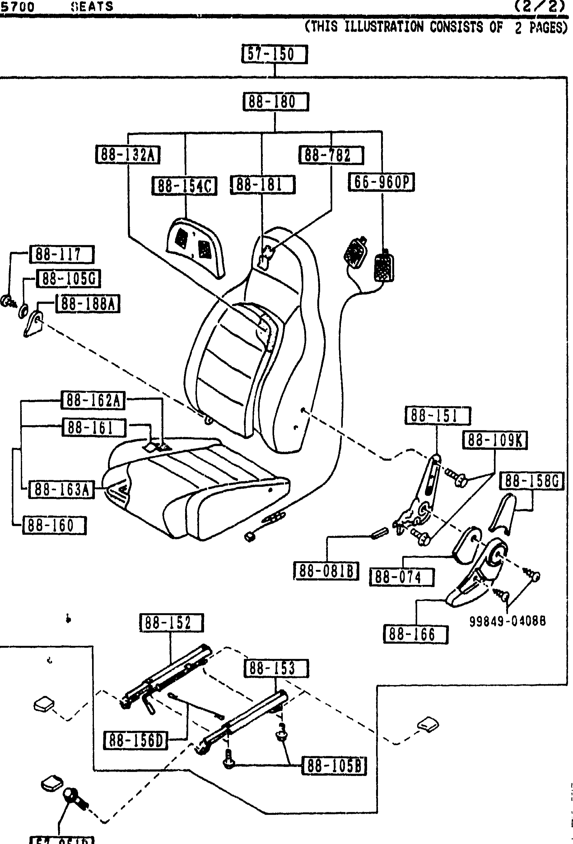
SEATS (2/2)
2-H10Exploded view of front seat assembly (2 of 2). Continues the parts call-outs from the previous page (2-G10). Shows seat back, cushion, headrest cover, recliner knuckle (L), adjusters No.3 and No.4 and assorted hardware. Callouts visible include 57-150 (seat top reference), 88-180, 88-32A, 88-54C, 88-181, 88-782, 88-109K, 88-105G, 88-188A, 88-117, 88-162A, 88-161, 88-163A, 88-151, 88-152, 88-156D, 88-158G, 88-160, 88-081B, 88-074, 88-152, 88-153, 88-156B, 88-105B, 88-166, 99849-04088, 57-051, 57-05X, 66-960P, 88-066, 88-152A.
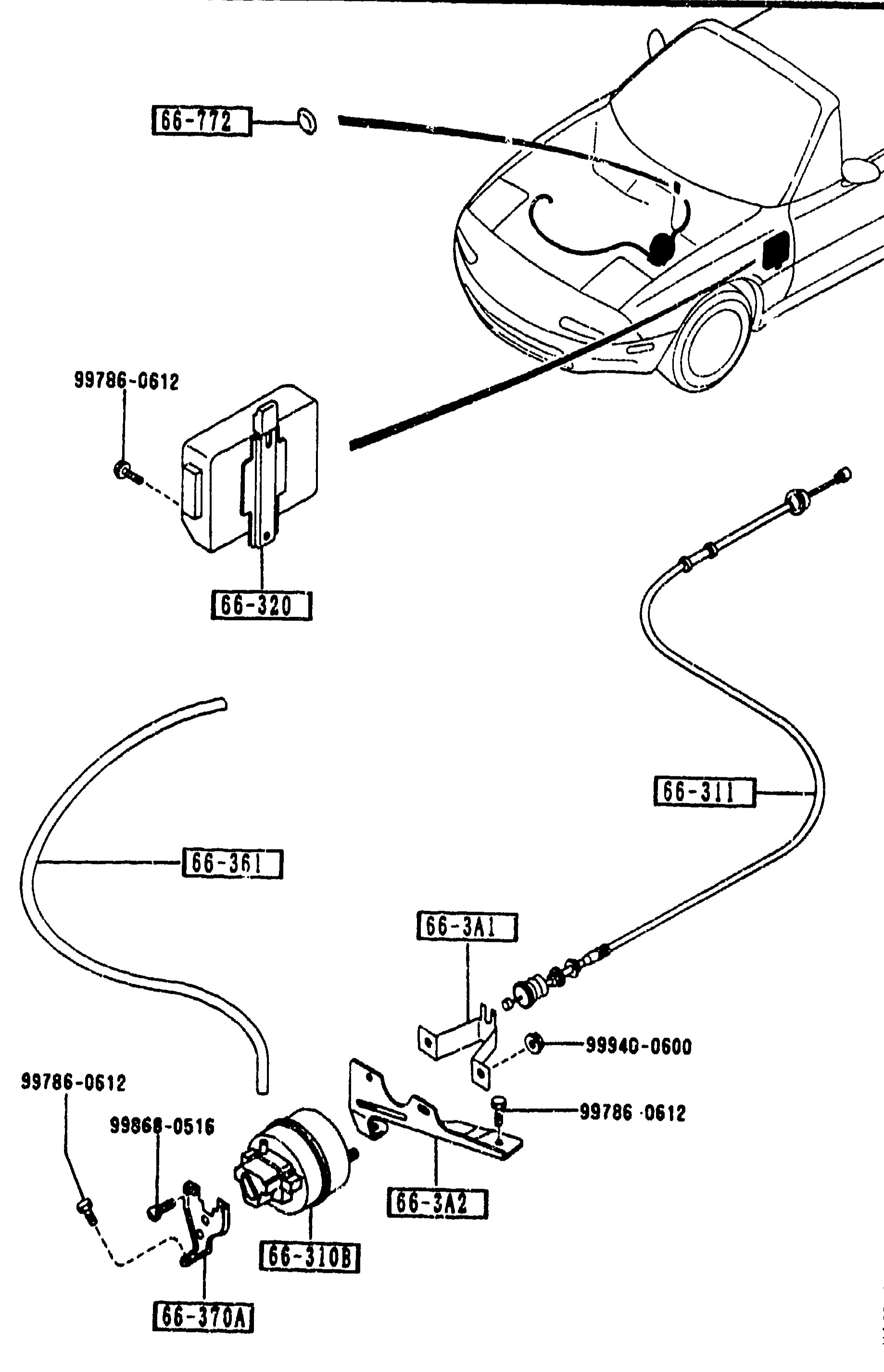
AUTO CRUISE CONTROL SYSTEM
2-H14Exploded view of the auto cruise control system. Top shows the front-of-car silhouette with the A.C.C. wire (66-311) routed from the box (66-320, mounted at top of front fender, secured by 99786-0612) into the engine bay. The grommet (66-772) seals the firewall pass-through. Bottom shows the actuator assembly (66-310B) with bracket (66-3A2) and pipe (66-361), plus an additional actuator bracket (66-3A1, 66-370A) and fasteners 99786-0612, 99940-0600, 99868-0516.
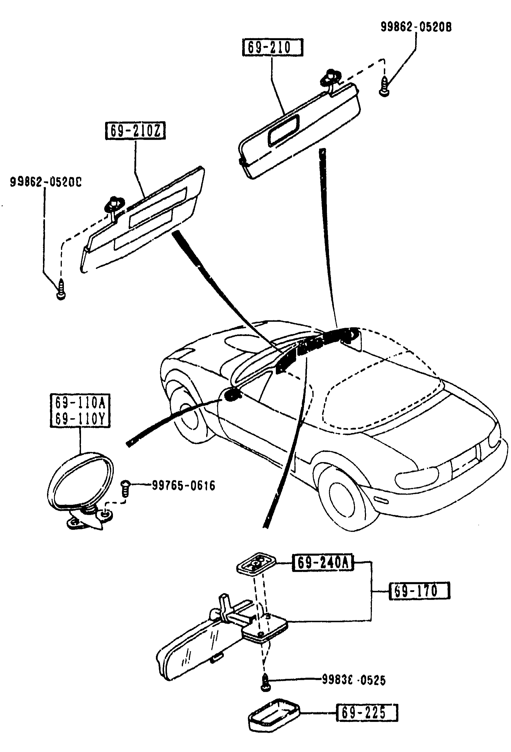
6900 VISORS, ASSIST HANDLES & MIRRORS
2-H16Exploded view of sun visors, door mirrors, interior mirror and assist handles on the MX-5. The vehicle silhouette shows the mounting locations. Callouts: 99862-0520B and 99862-0520C (screws) link to sun visors 69-210 and 69-210Y; 69-110A and 69-110Y label the door mirrors (R and L); 99765-0616 (screw) links to interior mirror assembly 69-240A / 69-170; 99830-0525 (screw) links to assist handle 69-225.
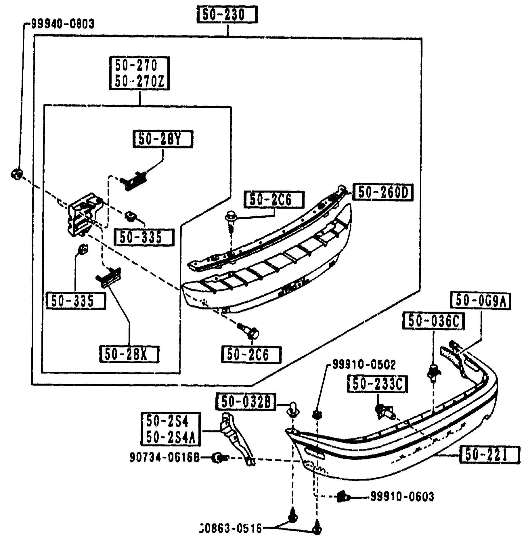
REAR BUMPER (5010) — continued
2-I 5Repeat of REAR BUMPER (5010) exploded view from page 2-H 5, showing the rear bumper cover, reinforcement bar, mounting brackets, stays and fasteners so the continued parts list on the right can still reference balloon callouts.
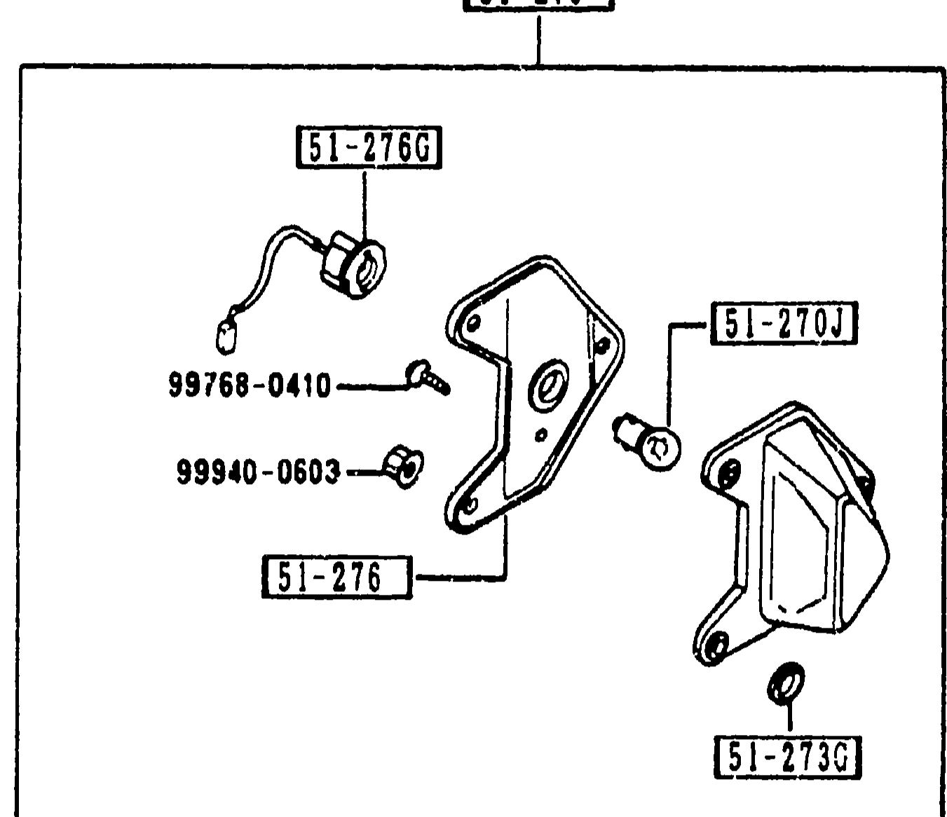
LICENSE LAMPS
2-I 6Exploded view of the license lamp assembly: lens 51-270J, gasket 51-273G, shade 51-276, socket 51-276G, with fasteners 99768-0410 and 99940-0603. Boxed/framed sub-figure.
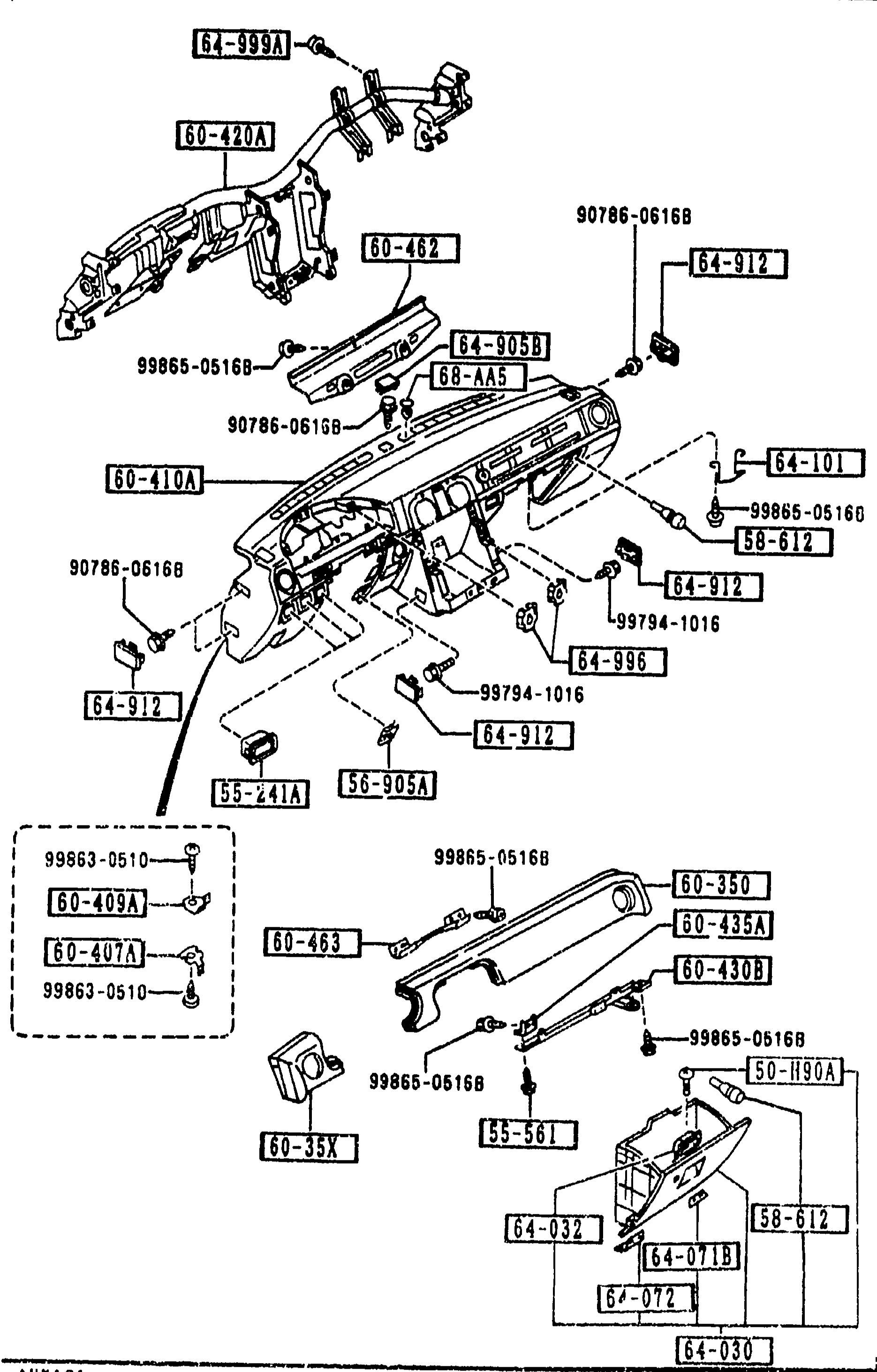
DASHBOARD & RELATED PARTS
2-I 9Exploded view of the MX-5 dashboard and related sub-trim. Top portion shows the full instrument-panel assembly (60-410A) with the upper crash-pad (60-420A/60-462), screw/clip fasteners (90786-0616B / 99865-0516B / 99794-1016 / 64-996 / 56-905A / 64-912 / 60-101 / 58-612 / 55-241A / 60-403 / 60-401A / 60-409A / 99863-0510 / 99865-0510B). Bottom-left shows the glove-box / inner trim sub-assembly (60-350 pad-crush, 60-435A, 60-430B, 60-410A, 60-420A frame, 64-072, 64-030, 64-032, 64-071B, 64-996 ash-tray opening), with multiple 99865-0516B fasteners.
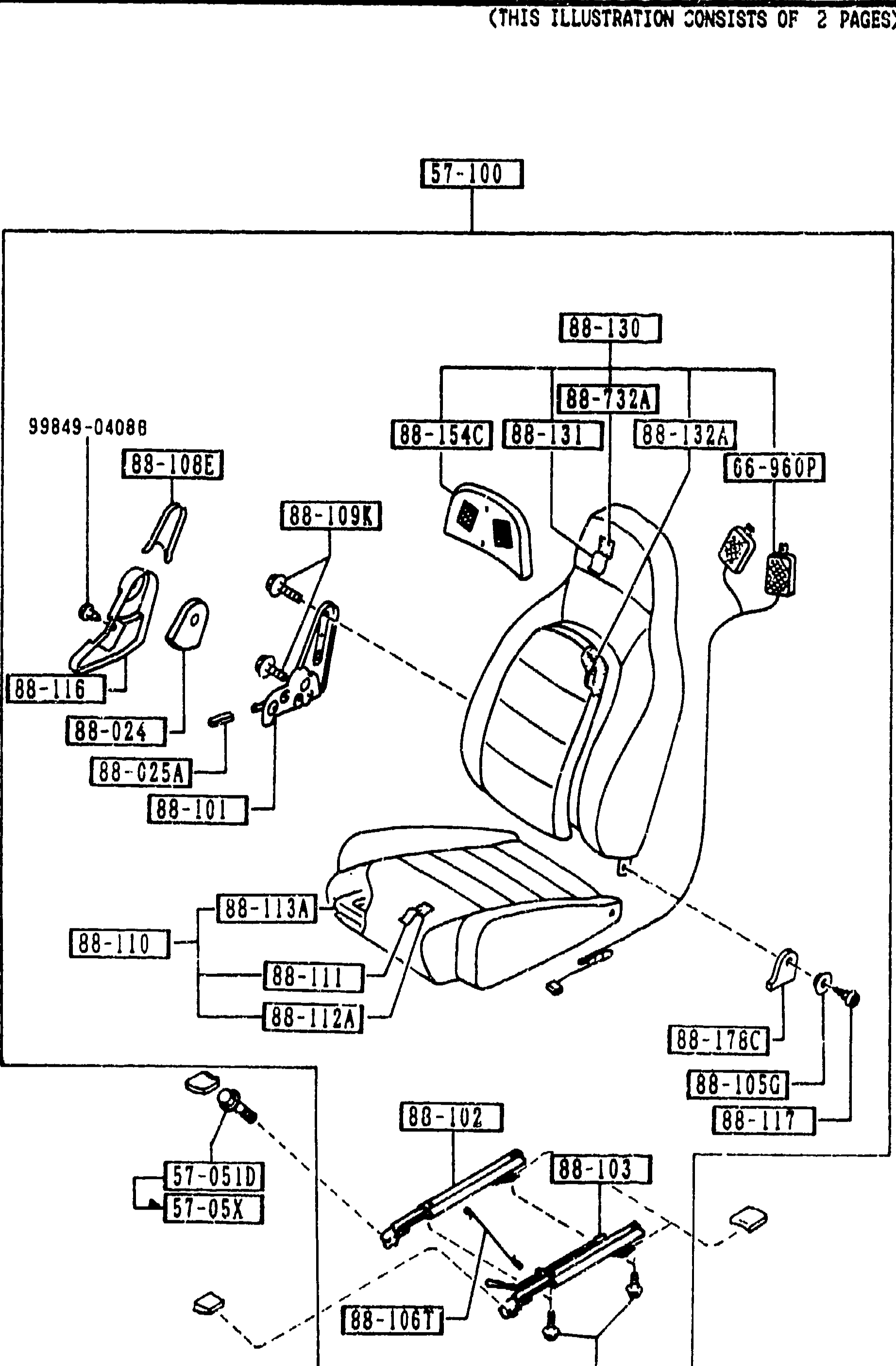
SEATS (1/2) CONT'D
2-I10Exploded view of left-hand front seat assembly (1 of 2). Mirror version of the right seat shown on prior pages. Visible balloon callouts: 57-100 (parent), 88-130, 88-732A, 88-31, 88-32A, 88-54C, 66-960P, 99849-04088, 88-108E, 88-109K, 88-116, 88-024, 88-025A, 88-101, 88-113A, 88-110, 88-111, 88-112A, 88-176C, 88-105G, 88-117, 88-102, 88-103, 88-106T, 88-105B, 57-051D, 57-05X.
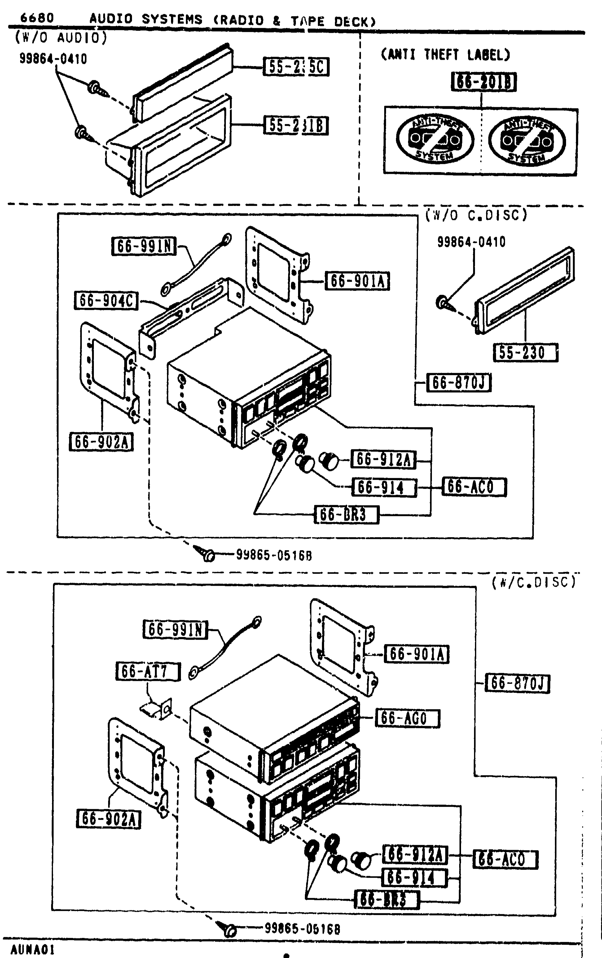
AUDIO SYSTEMS (RADIO & TAPE DECK)
2-I14Three exploded sub-views of the dashboard audio head-unit installation. Top-left shows the audio panel blanking trim (55-23C / 55-231B) and a screw (99864-0410). Top-right (inset, labeled 'ANTI THEFT LABEL') shows label 66-201B on a pair of round audio components. Middle (labeled 'W/O C.DISC') shows the standard radio + tape deck assembly: tuner/deck (66-AC0) inside frames 66-901A, 66-902A, 66-904C with knobs 66-912A, 66-914, 66-BR3 and panel 55-230. Bottom (labeled 'W/C.DISC') shows the same install with an additional compact disc player (66-AG0) stacked above the deck (66-870J), with bracket 66-AT7. Fasteners 99864-0410, 99865-0516B.
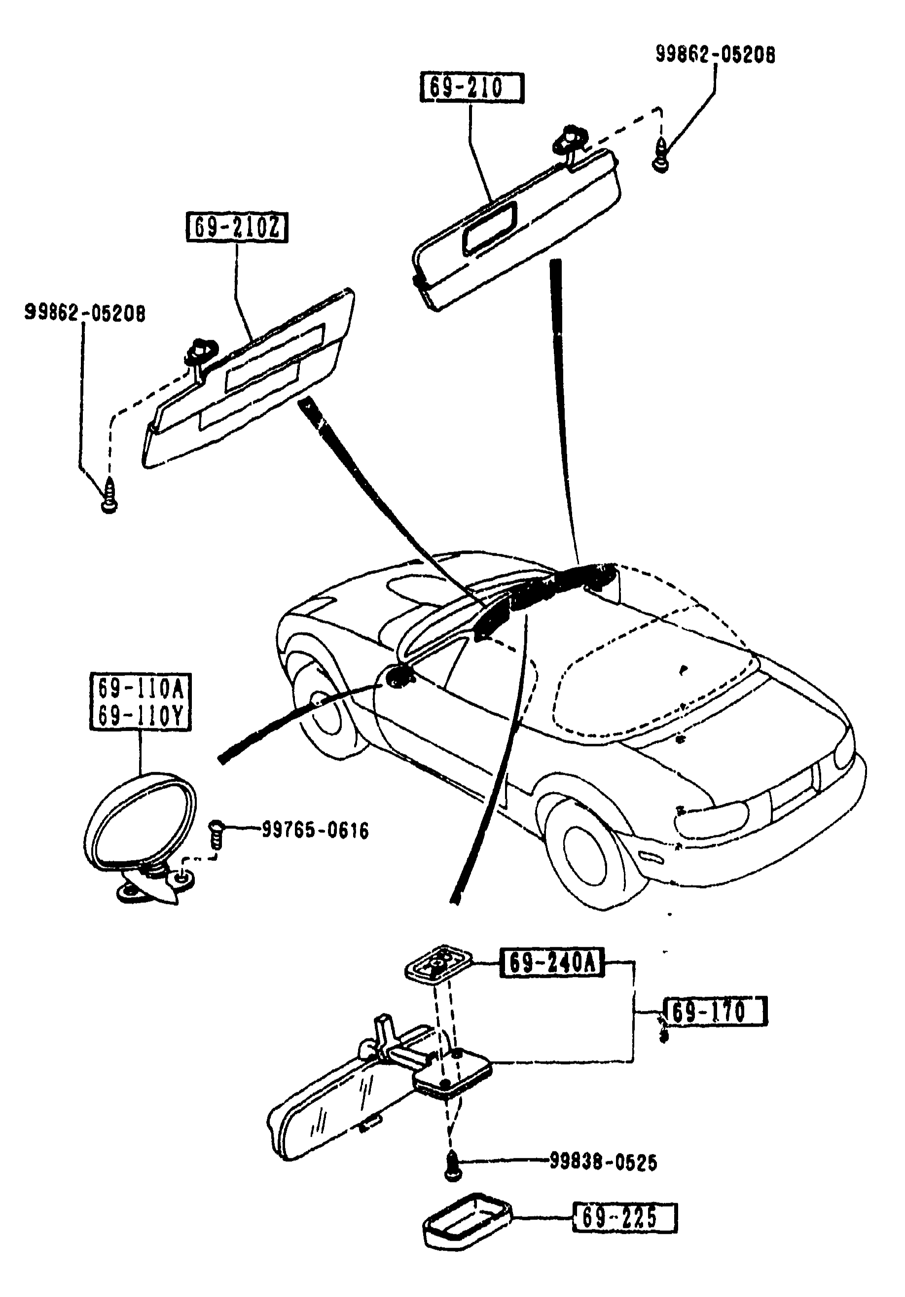
6900 VISORS, ASSIST HANDLES & MIRRORS (CONT'D)
2-I16Exploded view of visors, assist handles & mirrors continuation. Shows sun visor 69-210 with sub-part 69-210Z and screw 99862-0520B; door mirror 69-110A/69-110Y with screw 99765-0616; vehicle silhouette in middle; interior mirror sub-assembly 69-240A with mirror 69-170, base cover 69-225 and screw 99838-0525.
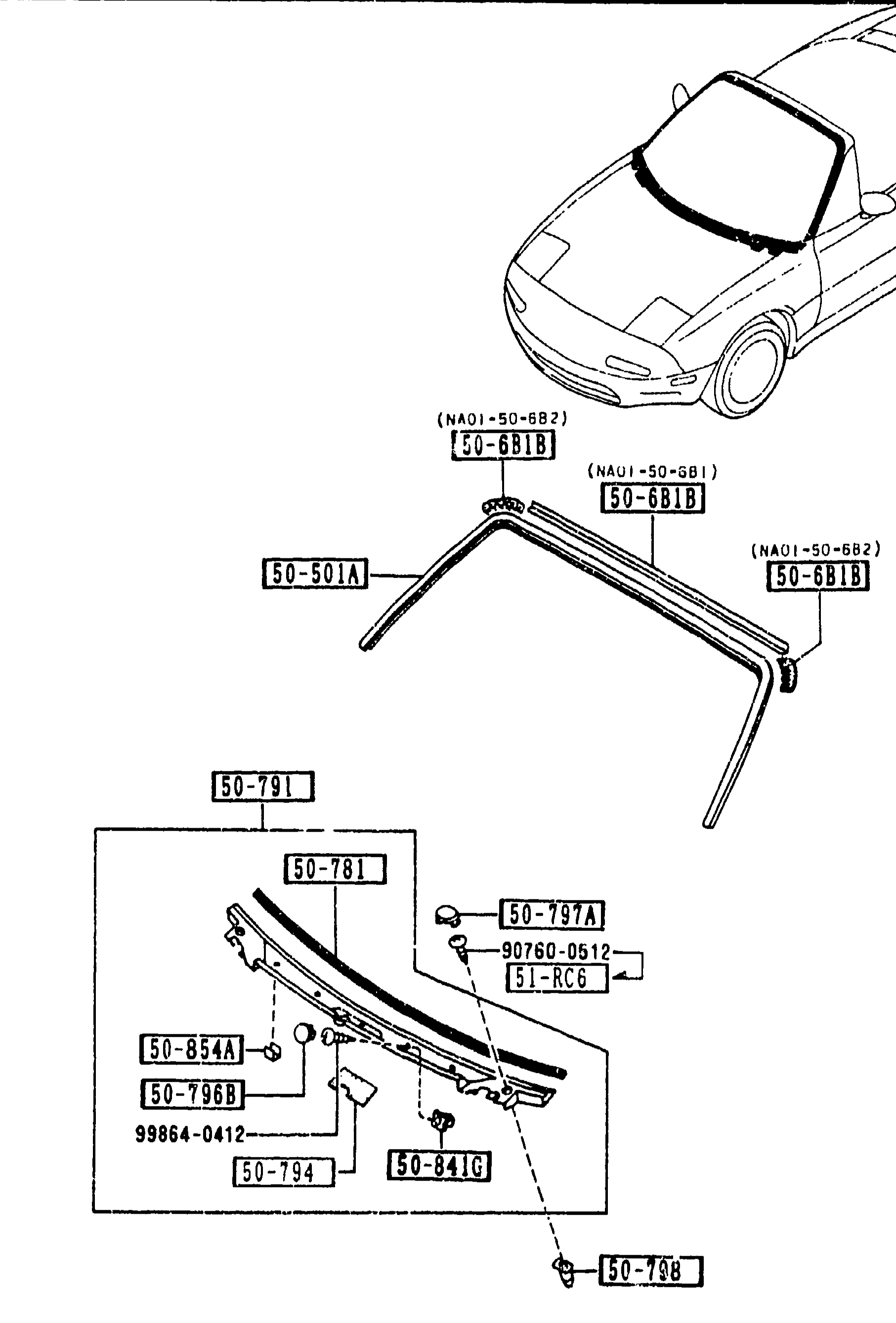
WINDOW MOULDING & COWL GRILLES (5030)
2-J 5Exploded view of WINDOW MOULDING & COWL GRILLES assembly (group 5030). Top shows a small 3/4 silhouette of the MX-5 front-end (vehicle position reference) with arrows pointing to the windshield-frame area. Below it the windshield top moulding (50-501A), corner/A-pillar moulding pieces (50-6B1B left & right) and the cowl-grille assembly (50-791) with its sub-parts: weather seal (50-781), screw-grommet (50-797A), grommets, protector (50-794) and side garnish screw (51-RC6). Balloon callouts identify each piece by short part number.
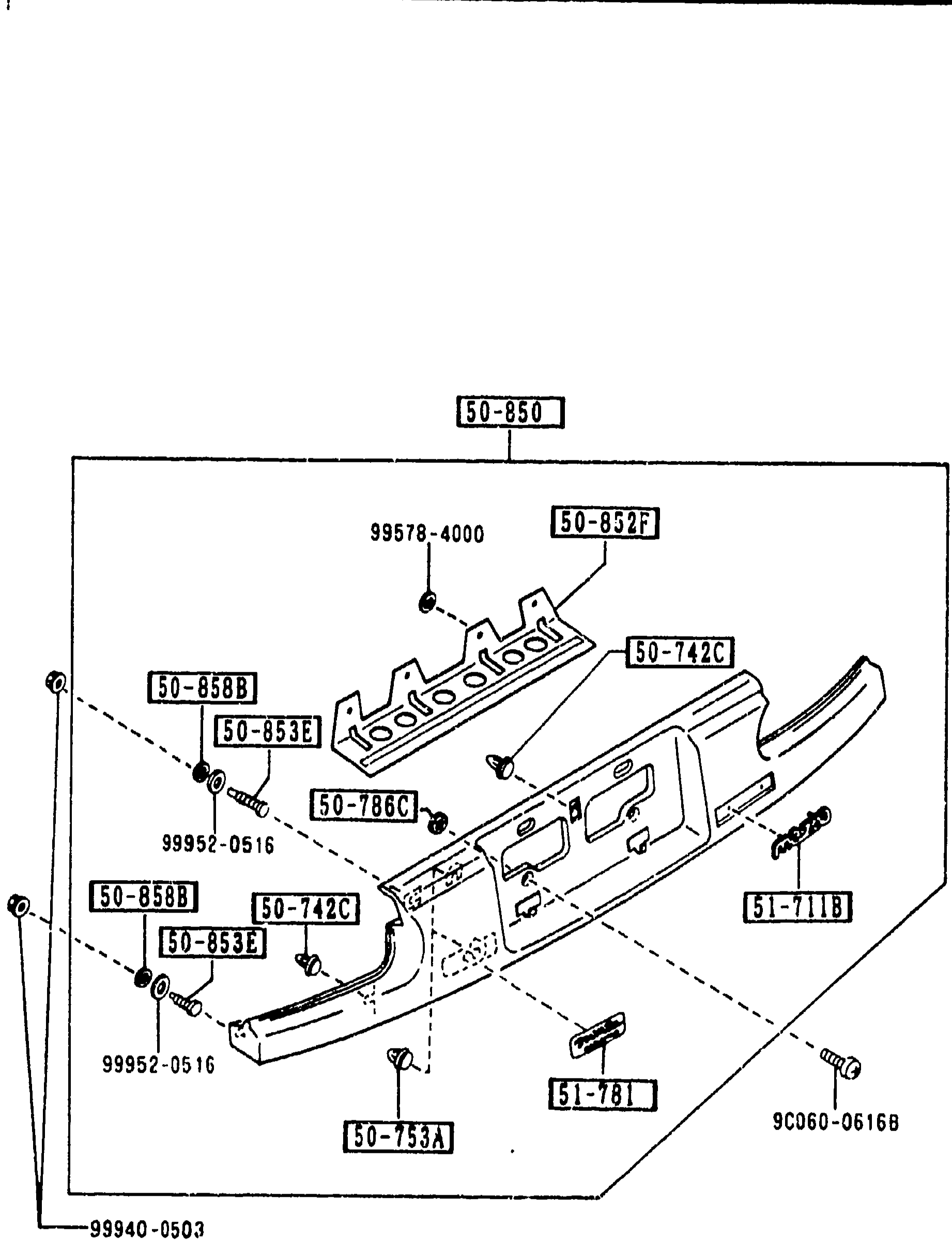
REAR FINISHER
2-J 6Exploded view of the MX-5 rear finisher (rear-panel garnish between tail lamps). Shows the finisher 50-850, the 'MAZDA' badge 51-711B, ornament 51-781, garnish-rear bolts 50-853E, clips 50-742C, fasteners 50-753A, gasket 50-786C, reinforcement 50-852F, cushions 50-858B/50-855B and screws 99578-4000, 99952-0516, 99940-0503, 9C060-0616B.
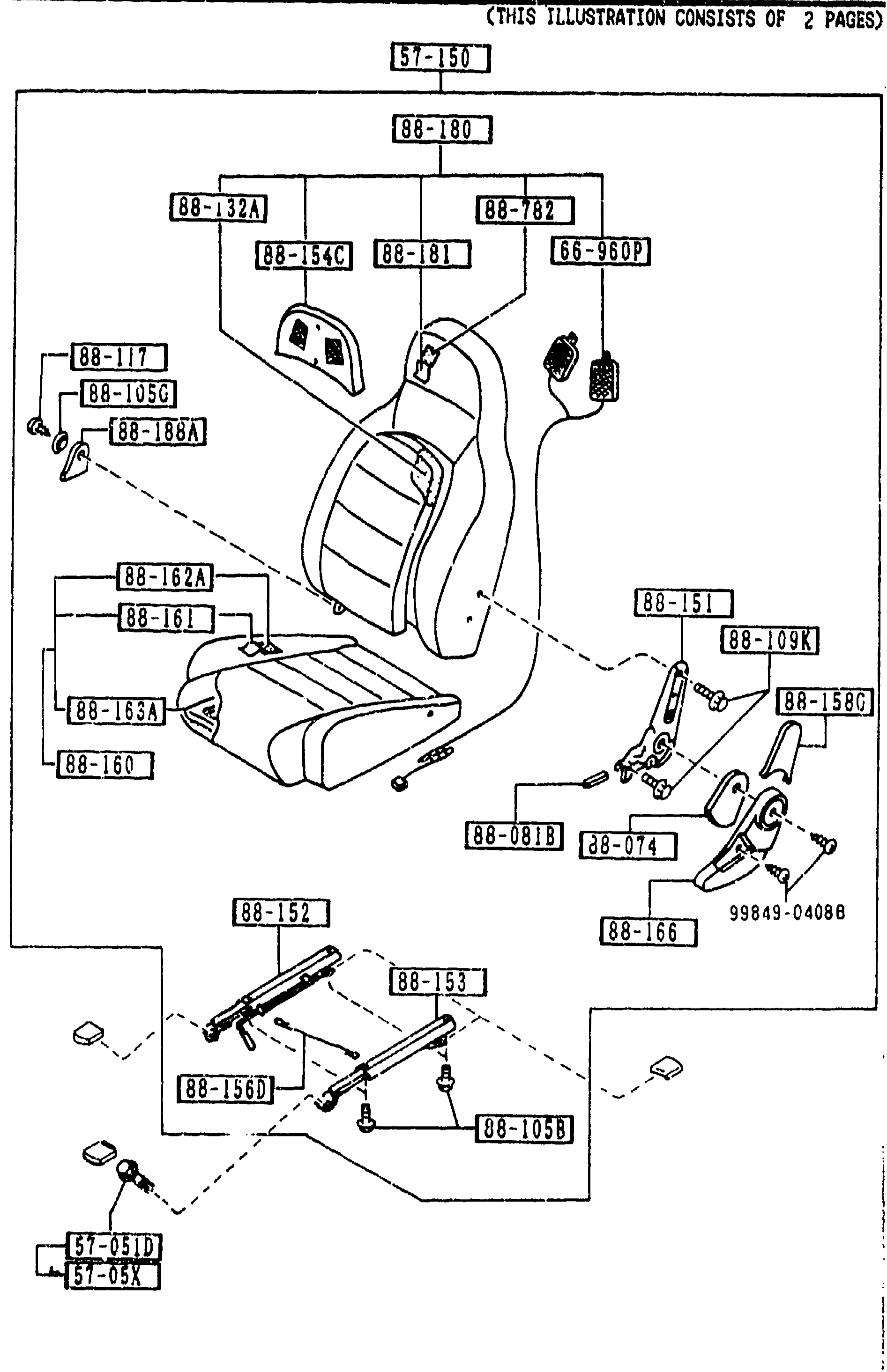
SEATS (2/2) CONT'D
2-J10Exploded view of left-hand front seat assembly (2 of 2). Continues from prior page. Visible balloon callouts: 57-150, 88-180, 88-132A, 88-782, 88-54C, 88-181, 66-960P, 88-117, 88-105G, 88-188A, 88-162A, 88-161, 88-163A, 88-160, 88-151, 88-109K, 88-158D, 88-081B, 88-074, 99849-04088, 88-166, 88-152, 88-53, 88-156D, 88-105B, 57-051D, 57-05X.
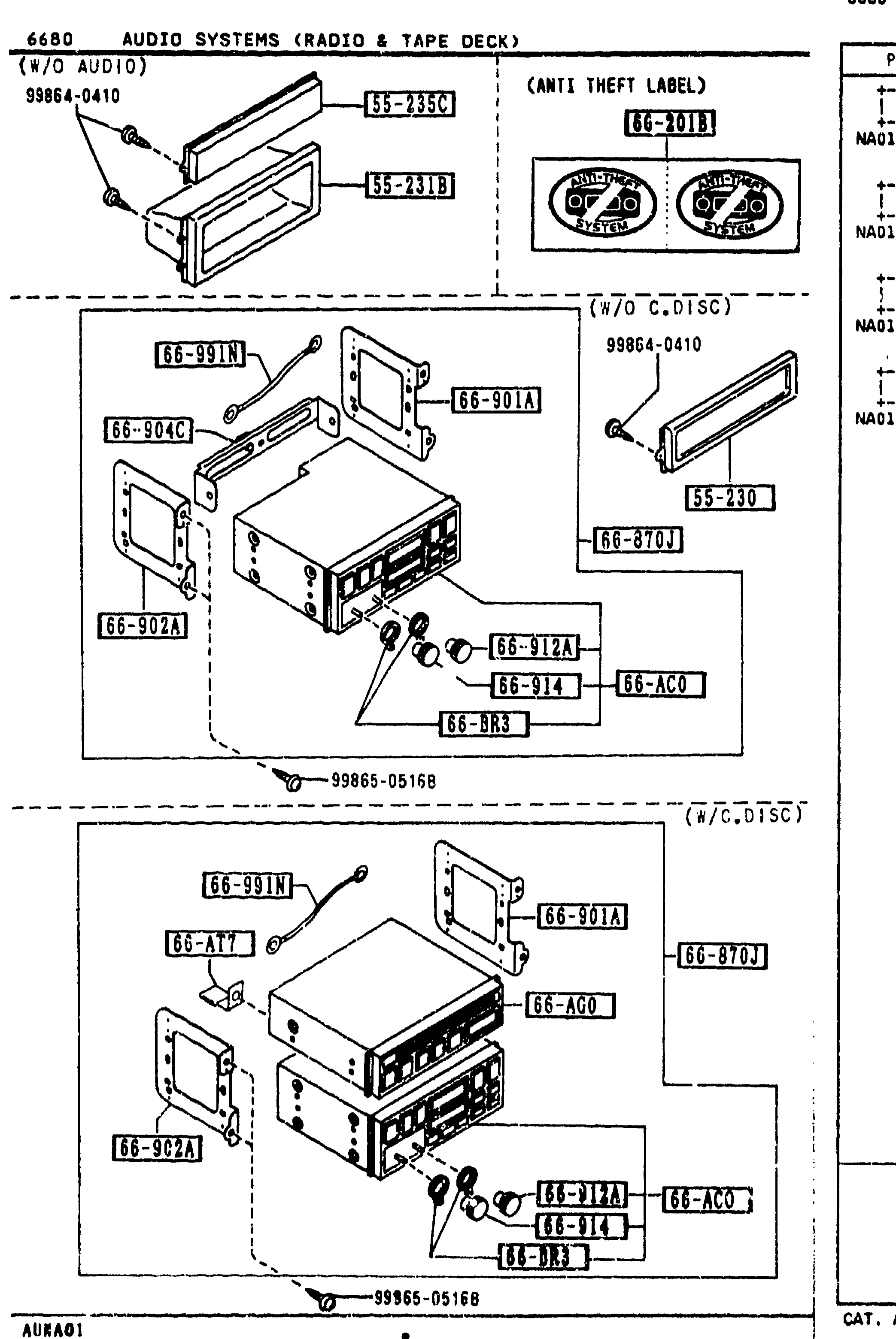
AUDIO SYSTEMS (RADIO & TAPE DECK)
2-J14Continuation of audio installation, sheet 2. Top-left (labeled 'W/O AUDIO') shows the audio blank panel trim (55-235C, 55-231B) and screw 99864-0410. Top-right (inset, labeled 'ANTI THEFT LABEL') shows label 66-201B on the round audio components. Middle (labeled 'W/O C.DISC') shows the tuner/deck assembly with brackets 66-904C, 66-901A, 66-902A, 66-870J body and knobs 66-912A, 66-914, 66-BR3 and panel 55-230. Bottom (labeled 'W/C.DISC') shows the assembly with the compact-disc player (66-AG0) stacked on top of the deck (66-870J), bracket 66-AT7, plus knobs 66-912A, 66-BR3, 66-914 and tuner/deck part 66-AC0. Fasteners 99865-0516B.
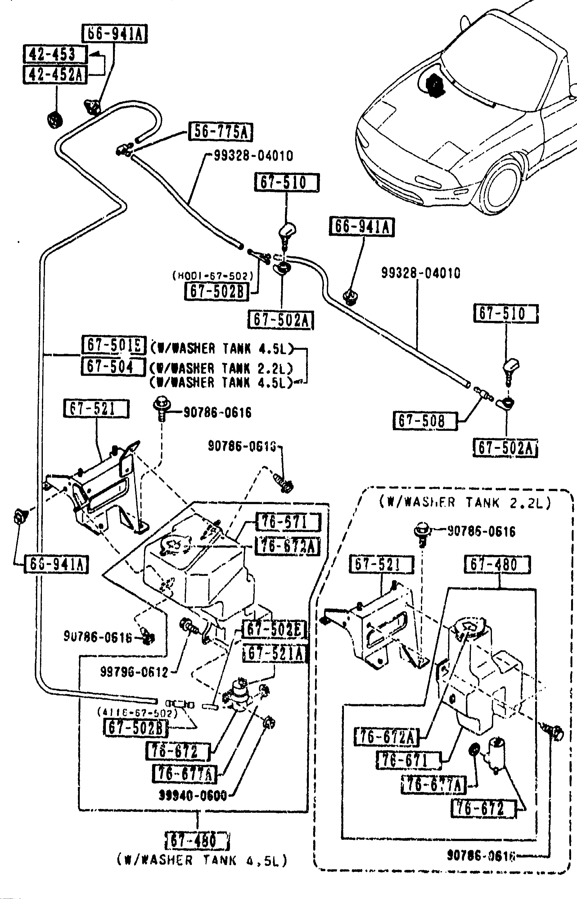
6720 WINDSHIELD WASHER (continued)
2-J15Continuation of the windshield washer exploded view from page 2-115. Same overall arrangement: hose run from cowl/firewall to hood washer nozzle, with two reservoir-tank variants (2.2L and 4.5L) shown as alternative sub-assemblies. Numbered balloon callouts identify nozzle, brackets, washer tank, washer pump motor, cap and grommet parts.
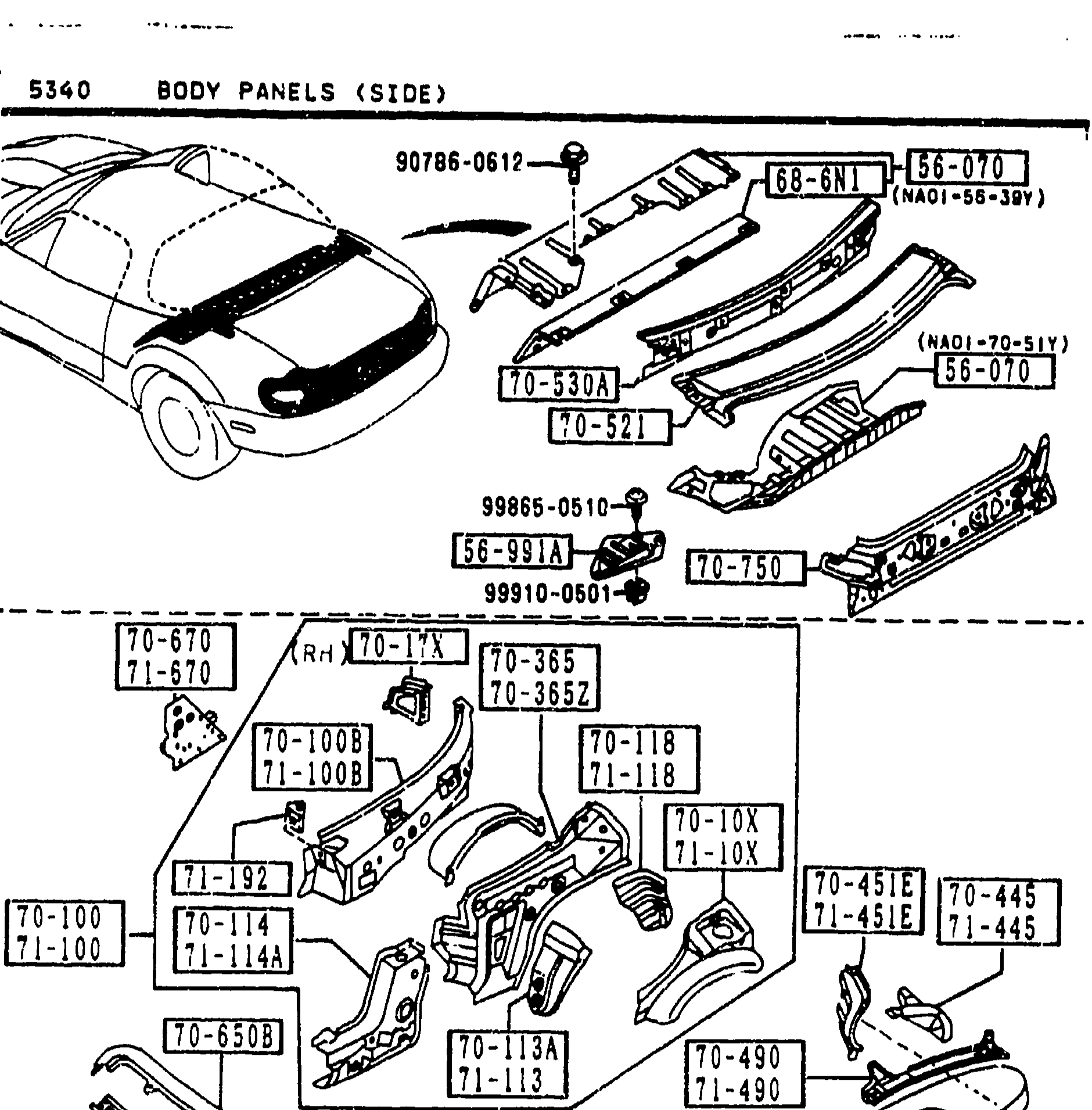
BODY PANELS (SIDE)
2-J7Exploded view of the MX-5 NA body side panels. Top sub-diagram shows the front body around the cowl/quarter area with balloons such as 90788-0617, 70-100, 70-100B (insulator bulkhead panel, cowl side panel, quarter panel). Lower sub-diagram shows the body shell from the side with a dense set of callouts including 70-100B, 70-100D, 70-118, 74-580A, 75-152, 70-112, 70-114, 70-117A, 70-126A, 70-210A, 70-230, 70-240A and tie-down/floor numbers like 99100-0510, 9931[?]-14430, 99987-1900 marking the rocker, inner pillar, splash protector, hinge pillar and front inner pillar areas.
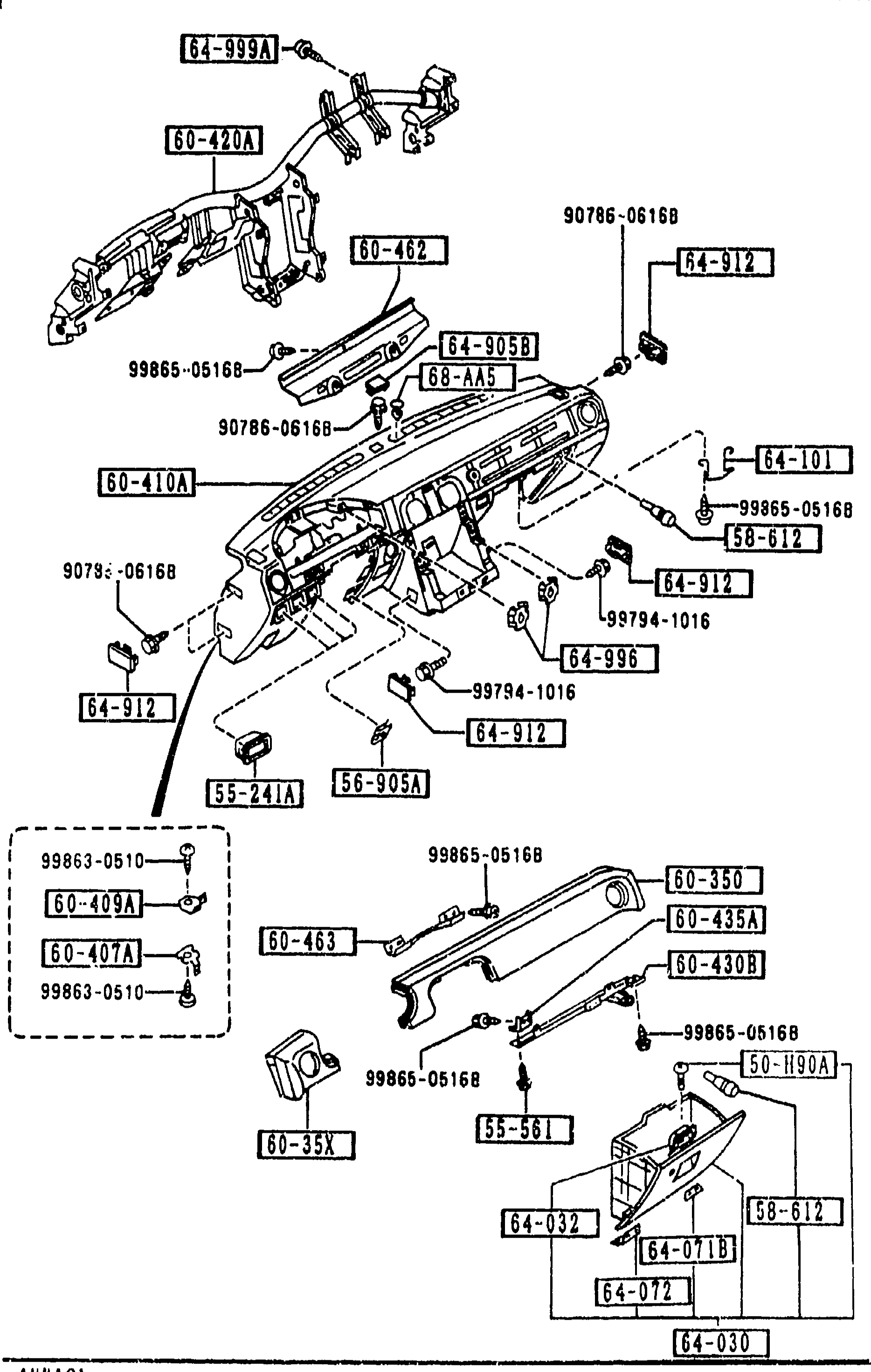
DASHBOARD & RELATED PARTS
2-J9Exploded view of dashboard / instrument panel assembly group 5560 (DASHBOARD & RELATED PARTS). Shows the main dashboard structural member (60-410A), reinforcement bracket (60-420A), wiring harness clip (64-999A), glove box and lid (64-030, 64-072, 64-071B), passenger crush pad (60-463), brackets (60-435A, 60-430B, 60-409A, 60-407A, 60-462), strikers (64-101), side cover (64-912), expansion nut (64-996), tapping screws (90786-0616B, 99865-05168, 99794-1016, 99863-0510), fastener (68-AA5), tappet (55-241A, 56-905A, 58-905A, 58-612, 60-350, 60-35X) and related fasteners. Each part shown with its balloon callout number.
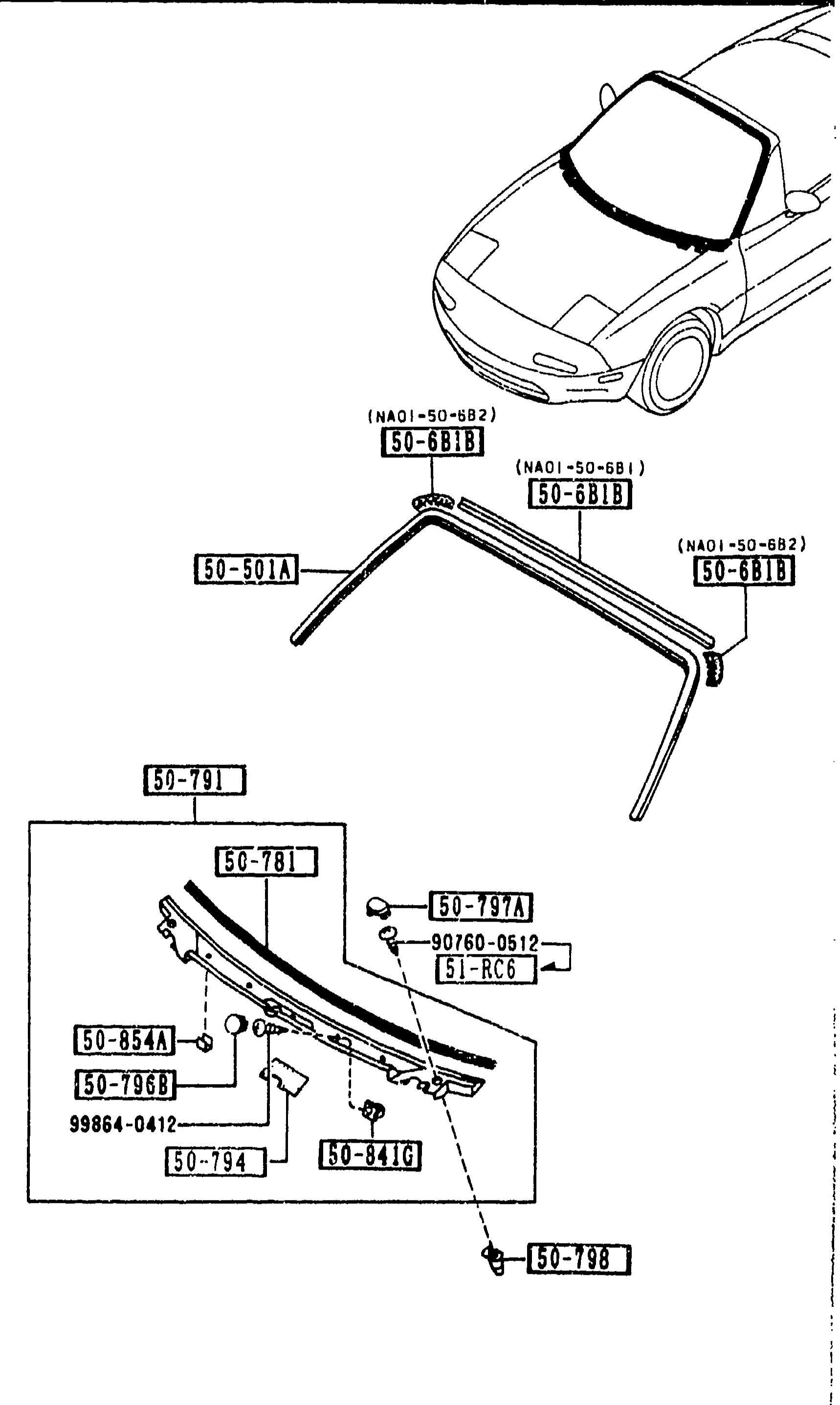
WINDOW MOULDING & COWL GRILLES (5030) — continued
2-K 5Repeat of WINDOW MOULDING & COWL GRILLES (5030) exploded view from 2-J 5: front-end vehicle silhouette, windshield mouldings (50-501A, 50-6B1B left & right with alt no. NA01-50-6B1/-6B2), and the cowl-grille assembly (50-791 / 50-781 / 50-797A / 51-RC6 / 50-854A / 50-796B / 99864-0412 / 50-794 / 50-841G / 50-798). Identical drawing to previous page.
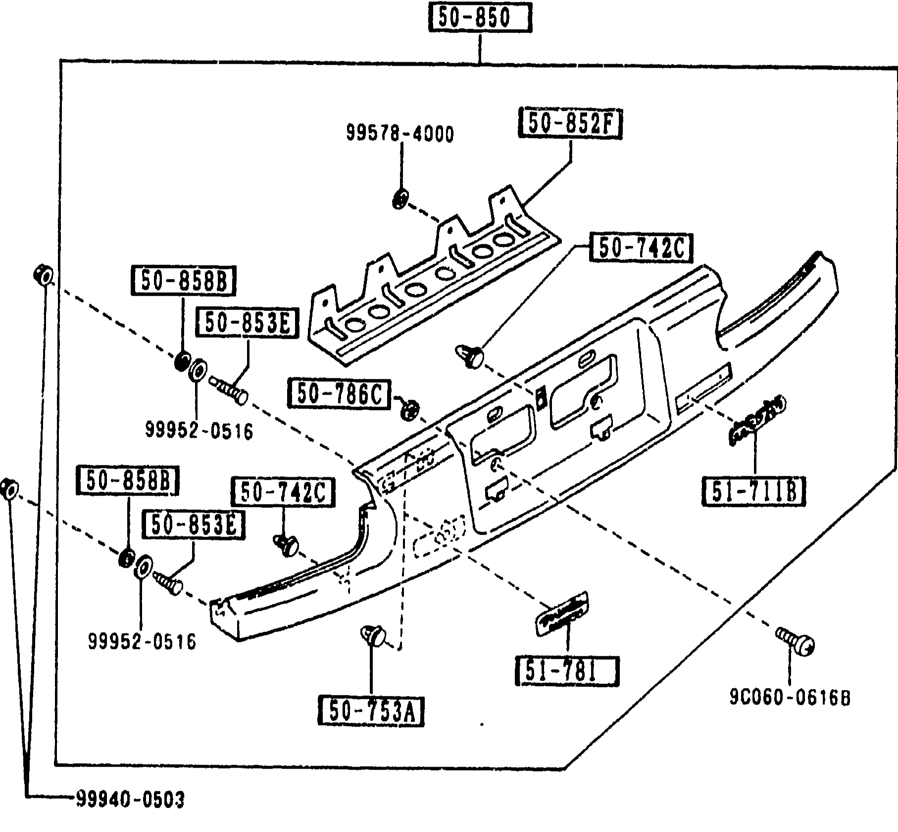
REAR FINISHER
2-K 6Boxed exploded view of the MX-5 rear finisher panel showing the finisher 50-850, reinforcement 50-852F, garnish bolts 50-853E, fasteners 50-858B, clips 50-742C, gaskets 50-786C, fasteners 50-753A, 99578-4000, 99952-0516, 99940-0503, MAZDA badge 51-711B, ornament 51-781, and bolt 9C060-0616B.
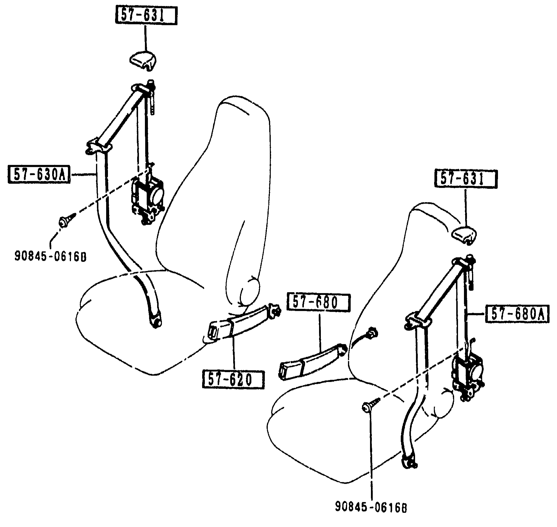
SEAT BELTS
2-K10Exploded view of front seat belt assemblies for both seats. Shows belt A (lap) and belt B (shoulder) for left and right front seats, with retractor/anchor mechanisms, anchor covers and mounting fasteners. Callouts: 57-620 (belt A), 57-630A (belt B(R), front seat), 57-631 (cover, anchor), 57-680 (belt A front), 57-680A (belt B(L) front), 90845-0616B (anchor bolt).
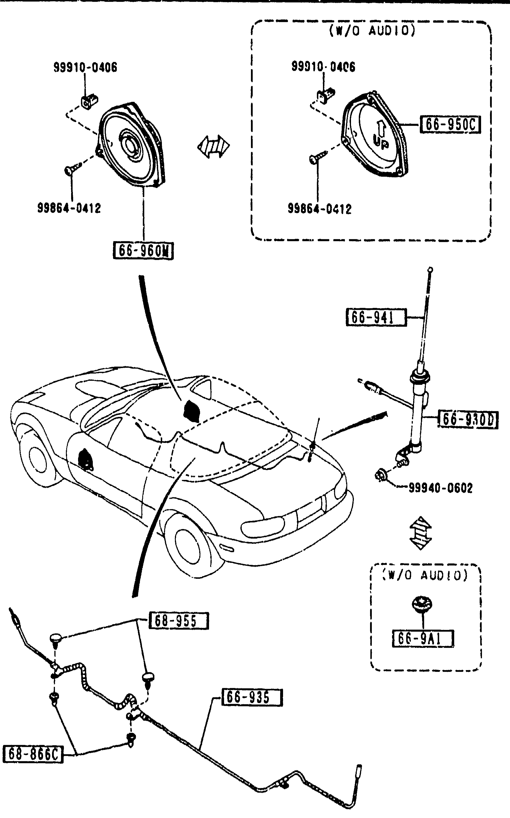
AUDIO SYSTEMS (ANTENNA & SPEAKER)
2-K14Exploded view of audio antenna and speakers for MX-5 NA convertible. Top-left shows the door speaker assembly (66-950C with bracket 66-360M and fasteners 99910-0406, 99864-0412), plus a (W/O AUDIO) inset showing the speaker blanking grommet (66-9A1). Middle shows the MX-5 silhouette with the antenna (66-941) on the LH front fender, feeder cable (66-830D) running into the dashboard, and the door-speaker location marked (66-950C, 66-360M, 66-940M). Bottom-left shows the antenna feeder routing under the floor: feeder cable (66-935) with fasteners (68-866C, 68-955) and ground point.
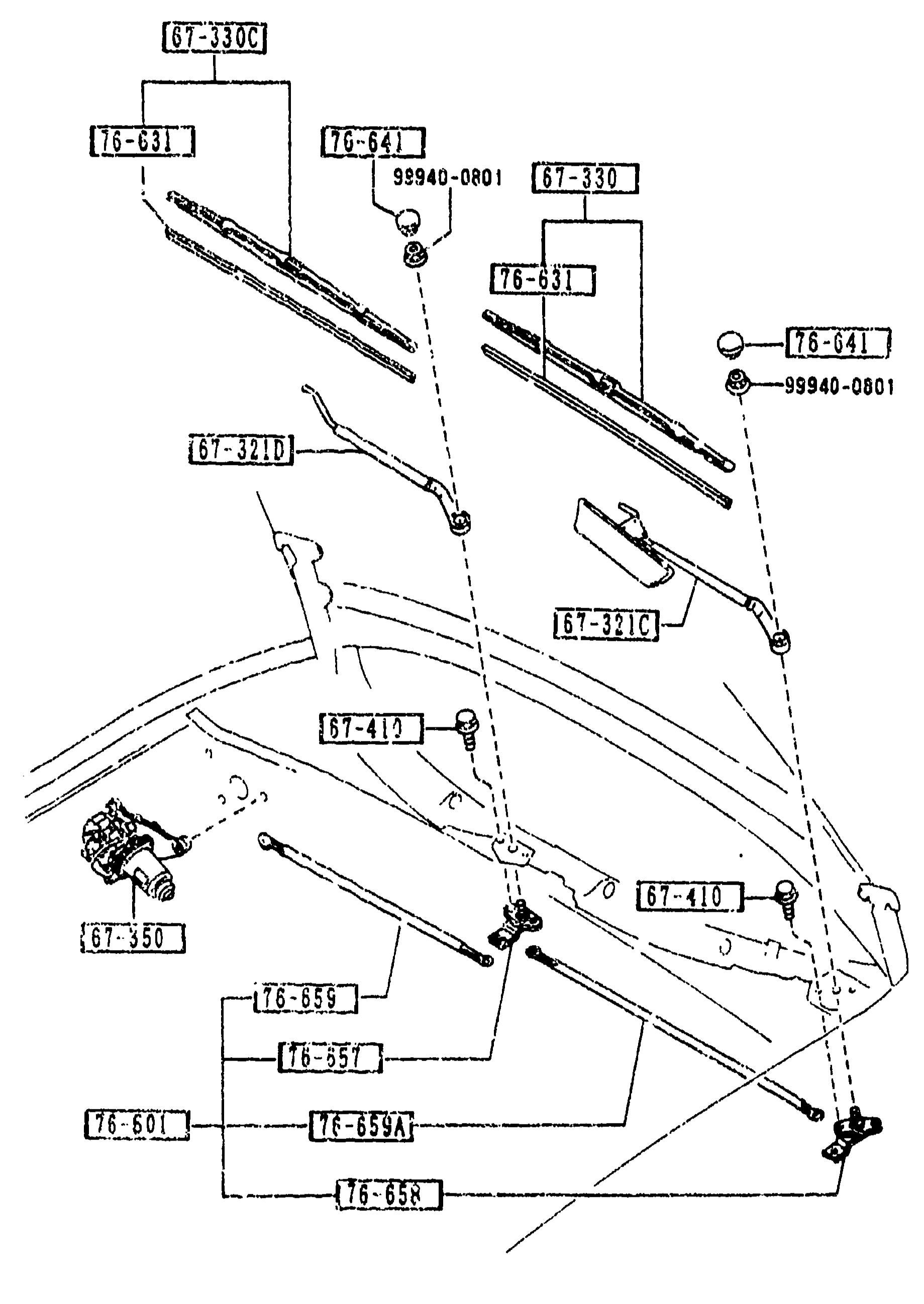
6730 WINDSHIELD WIPERS
2-K15Exploded view of windshield wiper assembly showing two wiper arms (driver and passenger), wiper blades, link mechanism, wiper motor and pivot shafts as installed across the cowl/firewall. Numbered balloon callouts identify arms, blades, motor, links, pivots and fasteners.
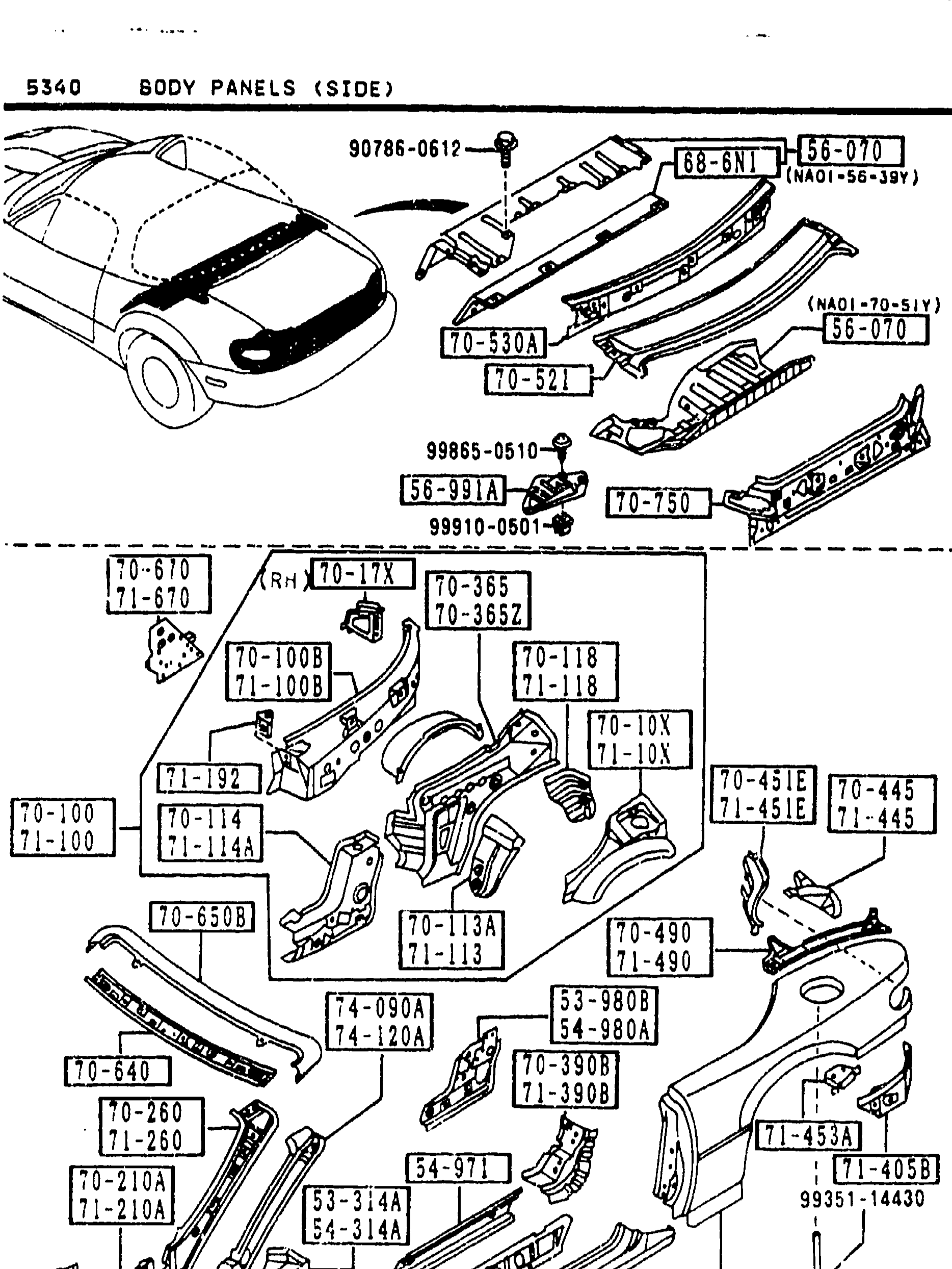
BODY PANELS (SIDE)
2-K7Continuation of the body side panels exploded view. Top sub-diagram shows the cowl/dash area with callouts including 90785-0617, 70-274, 70-2705 (gusset, side sill outer/reinf). Lower sub-diagram shows the body shell side view with balloons such as 70-100B, 70-100D, 70-274, 70-274A, 70-440, 70-365, 74-580A, 75-510A, 70-465E (housing lamp R fender), 70-521 (panel rear deck), and fastener references 99100-0510, 9931[?]-14430, 99987-1900.
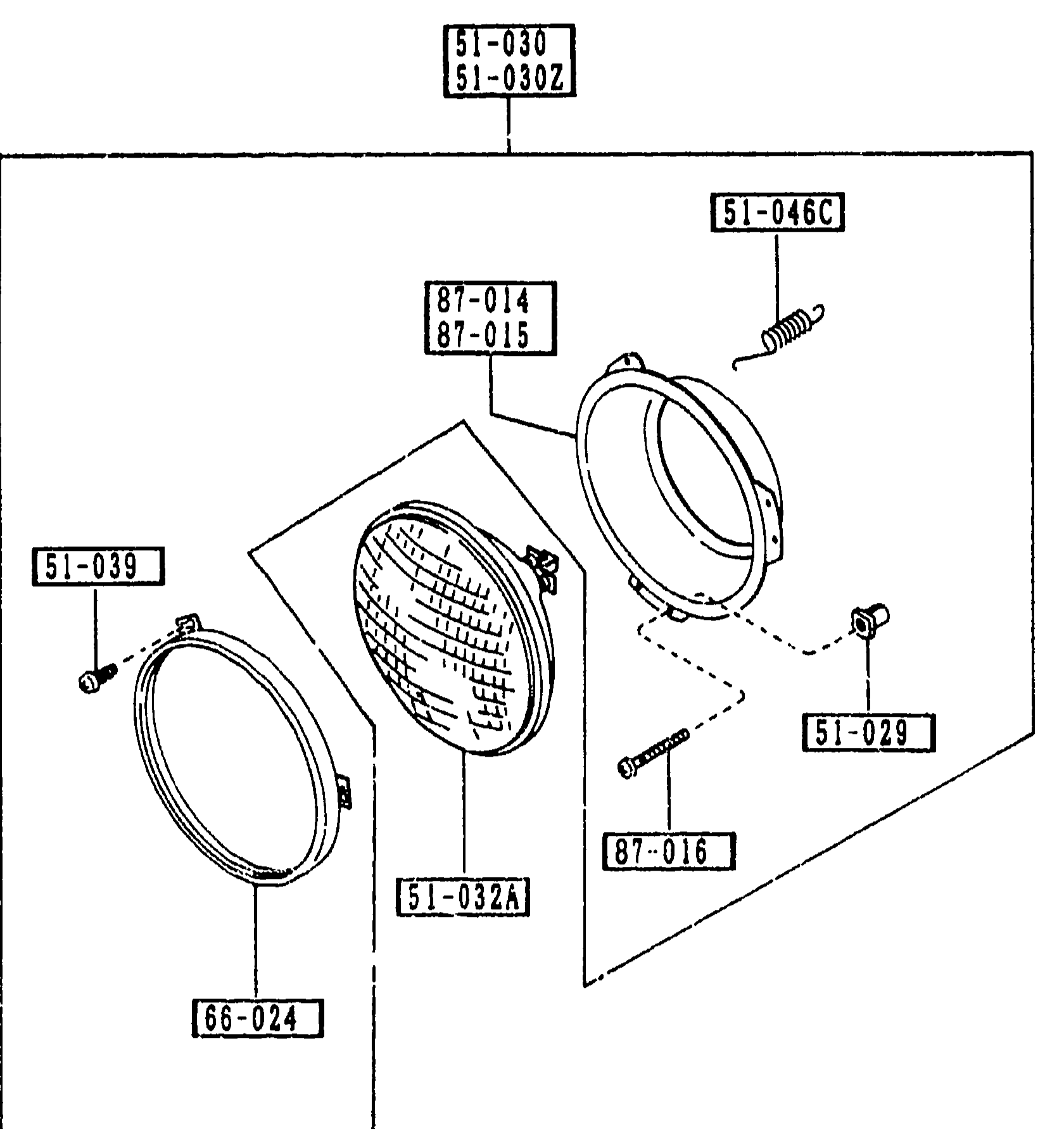
HEAD LAMPS (5100)
2-L 5Exploded view of HEAD LAMPS assembly (group 5100): retaining ring (66-024) at lower-left, sealed-beam unit / head lamp (51-032A) in the centre, mounting ring (87-014 / 87-015) over the lamp, return spring (51-046C) at upper-right, headlamp housing/bucket with adjusting screws (87-016) and grommets/screws (51-029, 51-039). The whole assembly is grouped under the lamp set boxes 51-030 (R) / 51-030Z (L).
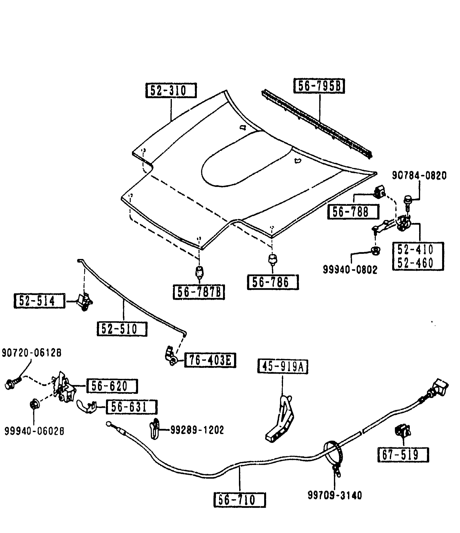
BONNET
2-L 6Exploded view of the MX-5 bonnet (hood) assembly. Top: bonnet panel 52-310 with weatherstrip 56-795B, hinges 52-410/52-460, stay 52-510, holder 52-514, and cushions 56-788, 56-786, 56-787B, 56-78X. Bottom: bonnet release mechanism with lock 56-620, fastener 56-631, release wire 56-710, pipe holder 45-919A, with bolts 90784-0820, 90720-0612B, 99940-0802, 99940-0602B, 99289-1202, 99709-3140, hook/bracket 76-403A, clip 67-519.
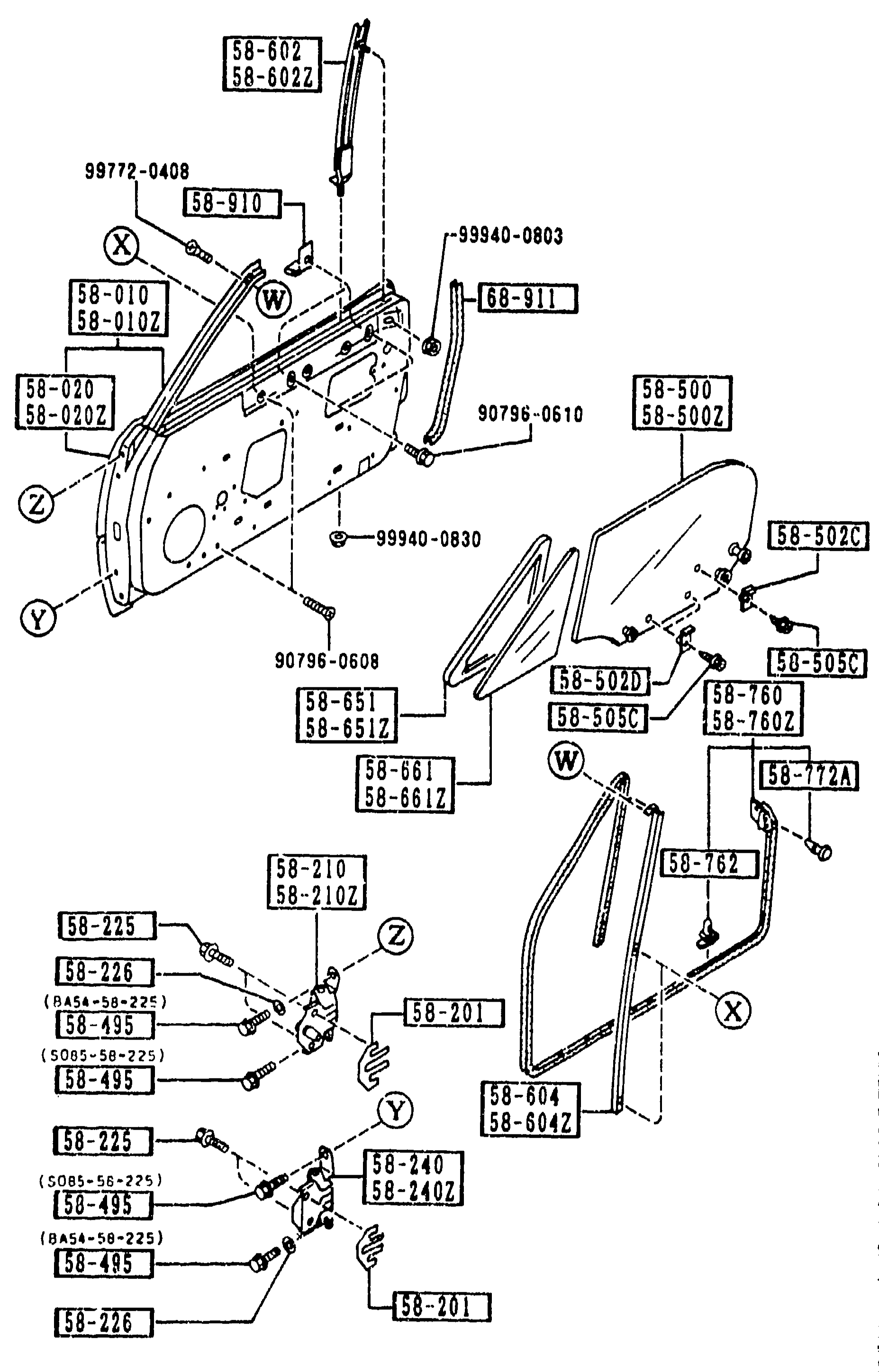
FRONT DOORS
2-L10Exploded view of front door assembly showing door panel/body shell, upper and lower hinges, door glass with weatherstrips and frames, anti-vibration shims and setting bolts/washers. Coordinate-style locator letters W/X/Y/Z mark hinge and trim positions. Callouts include 58-602/58-602Z (upper frame), 58-010/58-010Z (body R/L), 99772-0408 (fastener), 58-910 (bolt assembly), 99940-0803/99940-0830 (fasteners), 58-911 (clip), 58-020/58-020Z (body, FRT door panels), 58-500/58-500Z, 90796-0610 (bolt), 58-651/58-651Z, 58-661/58-661Z, 58-201, 58-210/58-210Z (hinge upper R/L), 58-225 (setting bolt), 58-226 (washer setting), 58-495 (bolt set), 58-240/58-240Z (hinge lower R/L), 58-502C, 58-505C, 58-760/58-760Z, 58-72A, 58-762, 58-604/58-604Z.
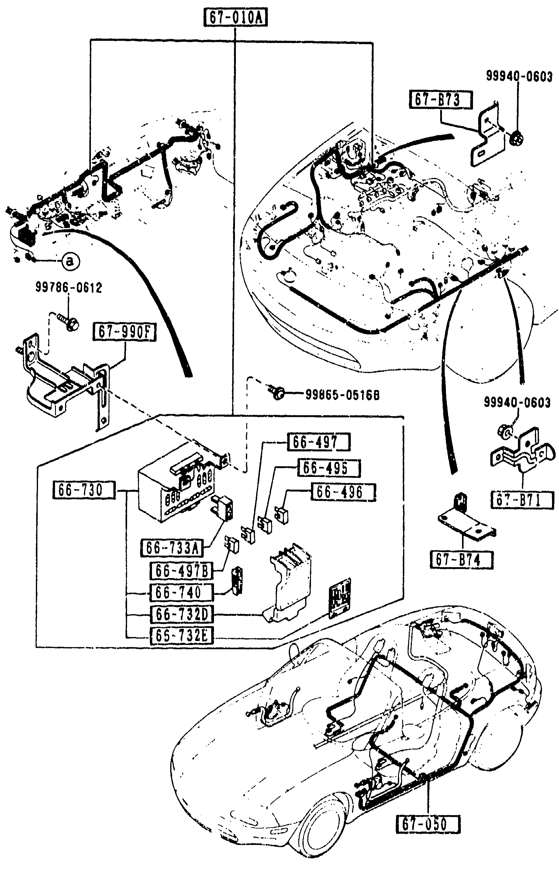
WIRING HARNESSES (FRONT & REAR)
2-L14Exploded view of MX-5 front and rear wiring harnesses. Top-left shows the engine-bay harness routing over the front of the vehicle with callouts identifying harness sub-assemblies and mounting brackets. Middle-left shows the fuse block assembly with individual fuses and the fuse box cover labelled. Bottom-left shows a 3/4 vehicle silhouette with the main harness routing along the body. Balloon callouts: 67-010A (HARNESS, FRONT), 67-873 / 67-874 / 67-871 / 67-990F (BRACKET, HARNESS), 66-497 / 66-497B / 66-498 / 66-740 / 66-733 / 66-730 / 66-733A / 66-732C / 66-732D (FUSE BLOCK and related), 67-050 (rear harness routing). Hardware part numbers shown: 99940-0603, 99786-0612, 99865-05168.
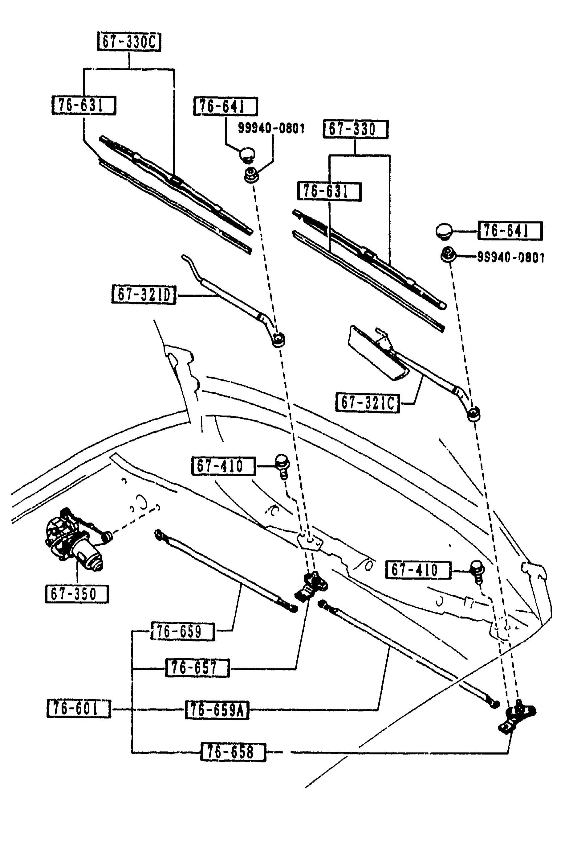
6730 WINDSHIELD WIPERS (continued)
2-L15Continuation of windshield wiper exploded view from page 2-K15: same wiper assembly layout (driver and passenger arms, blades, link assembly, motor) with additional callouts highlighting the drive shafts (76-657, 76-658) and link arms (76-659, 76-659A).
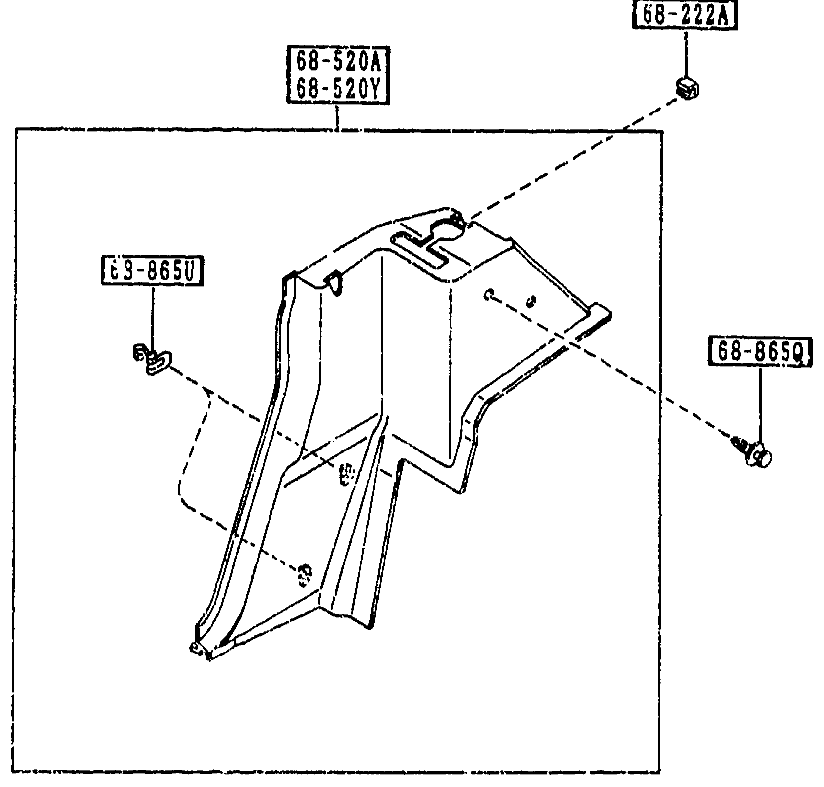
7250 QUARTER WINDOW & TRIMS
2-L16Exploded view of the MX-5 quarter-window trim panel. Shows main trim part (68-520A R / 68-520Y L), hole-cover plug (68-222A) fixed at the top, trim clip (68-865U) on the lower-left, and fastener (68-865Q) on the right side.
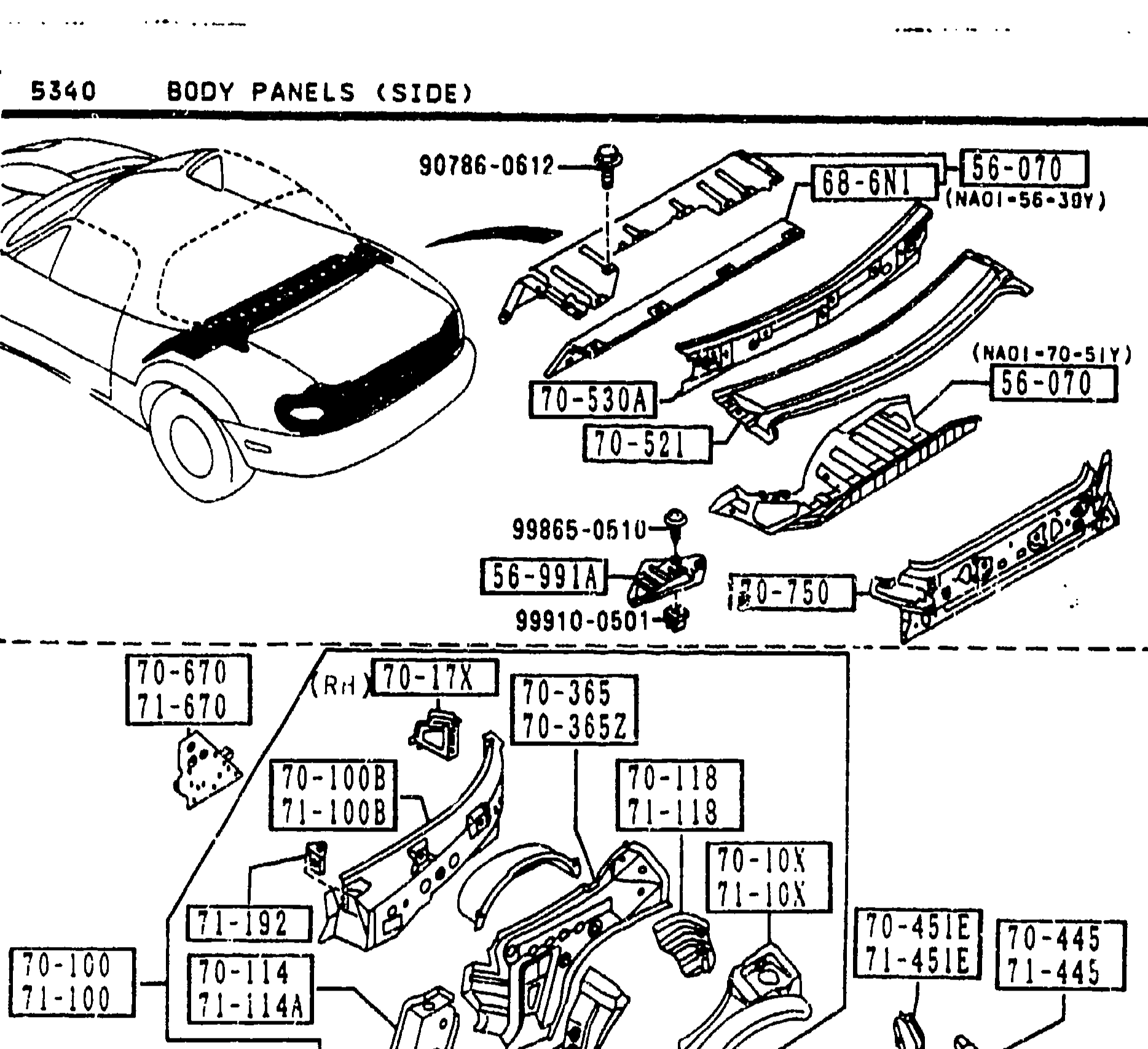
BODY PANELS (SIDE)
2-L7Top sub-diagram shows the front cowl and front header area with balloons including 90786-0617, 70-665, 70-665N (header front, header front upper), 70-670 (plater R closing qtr panel), 70-750 (panel rear end) and fastener 99100-0510 / 99987-1500. Lower sub-diagram shows the body-side shell with callouts including 70-100B, 70-100D, 71-020, 71-100, 71-110, 71-100E, 70-260, 71-100B, 71-110E, 71-112 — front fender, quarter, inner, seal plate area.
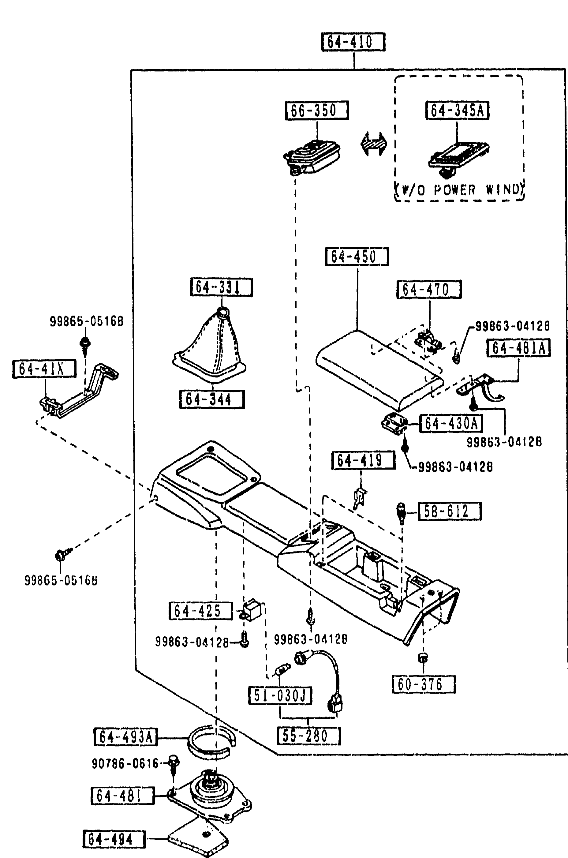
CONSOLE
2-L9Exploded view of group 5570 (CONSOLE). Shows the rear console body (64-410), front console base/sub-base (64-450, 64-345A, 64-481A, 64-419, 64-470, 64-430A), boots and plates (64-331, 64-344, 64-481, 64-493A, 64-494), warning lamp bulb (51-030J), bulb and socket sub-assemblies (55-280), urethane knob bases (64-416, 64-41X), boot stopper plate (64-425, 64-471X), shift boot retainer (64-425), rubber cushion (58-612), top-crush nut (60-376), tapping screws (90786-0616B, 99865-05168, 99863-04128), and inline harness retainers and clips.
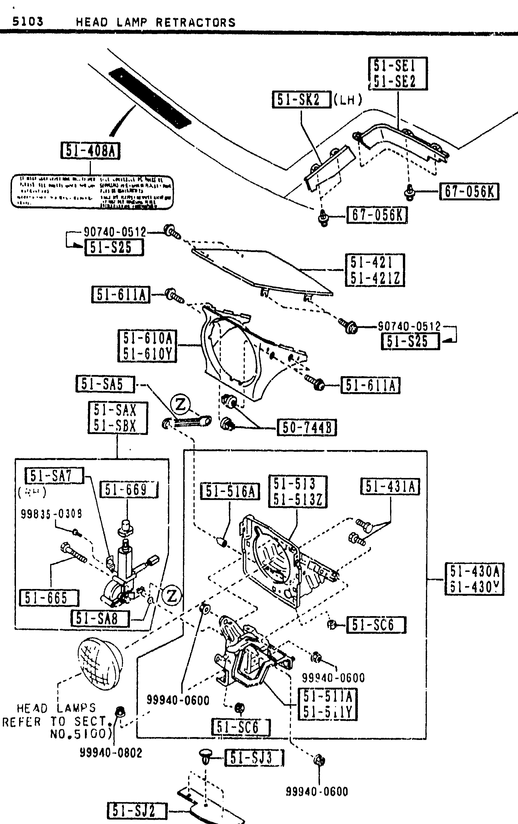
HEAD LAMP RETRACTORS (5103)
2-M 5Exploded view of HEAD LAMP RETRACTORS (group 5103) — the pop-up headlamp mechanism. Top shows the retractor caution label (51-408A) on the inner fender. Centre shows the lid/door (51-421, 51-421Z), hinge brackets (51-430A, 51-430Y), retractor motor with cover (51-SAX motor R, 51-SBX motor L), retractor rod (51-SA5), retractor housing/bracket (51-513, 51-513Z), pivot arm (51-516A) and head-lamp protector covers (51-SE1/-SE2 R, 51-SJ2/-SJ3 L). A 'HEAD LAMPS (REFER TO SECT. NO.5100)' callout points to the headlamp itself at bottom-left.
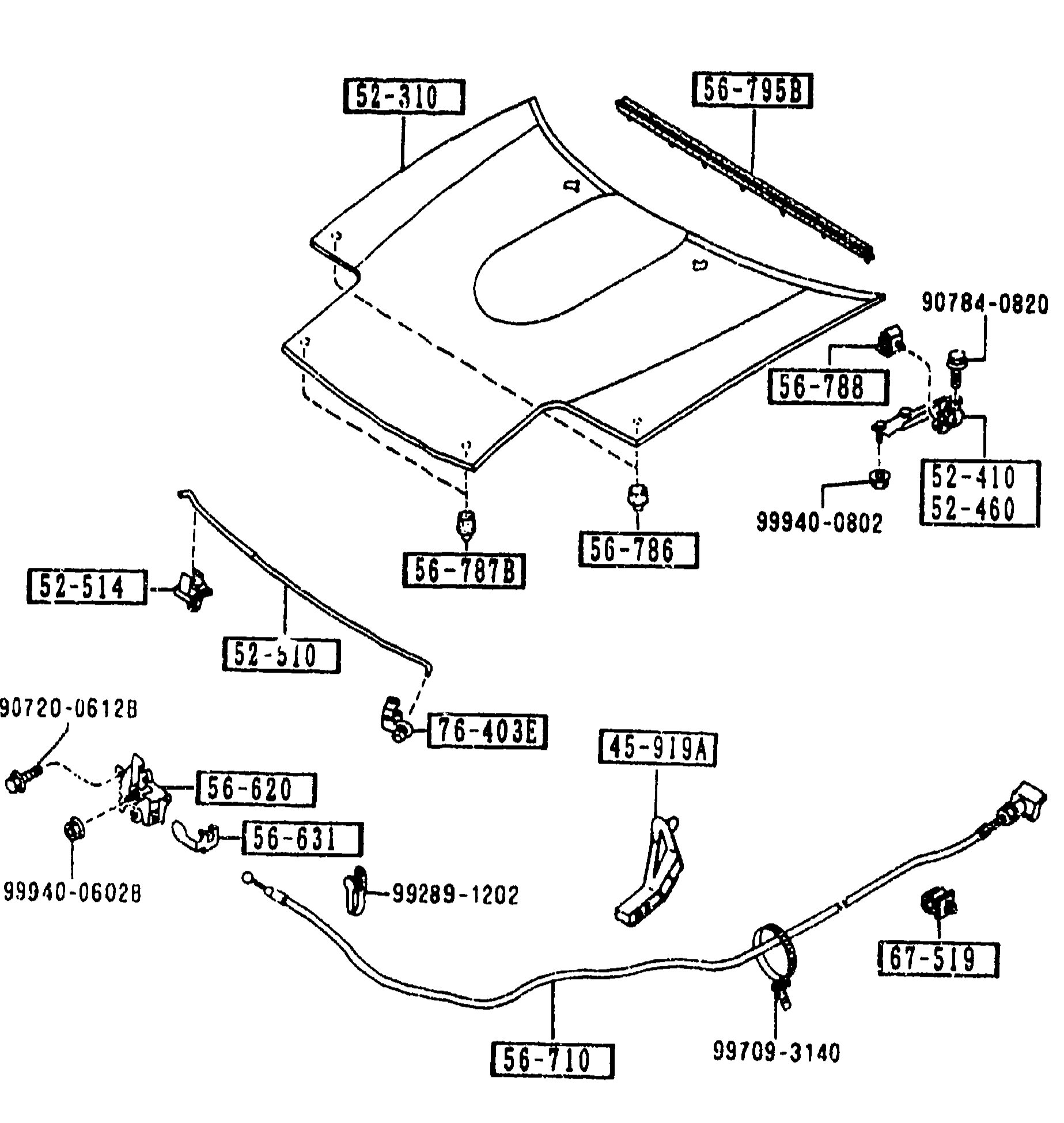
BONNET
2-M 6Exploded view of the bonnet (hood) assembly showing the hood panel with weatherstrip [56-795B] and panel [52-310], hinges [52-410, 52-460], catch/release [56-788, 99940-0802, 90784-0820], stay [56-787B, 56-786], release cable [76-403E, 52-514, 52-510], lock latch [56-620, 56-631, 90720-0612B, 99940-0602B], cable [56-710, 99709-3140], cable mount [45-919A, 99289-1202], and clip [67-519]. Part numbers are shown in boxed callouts with leader lines pointing to each component.
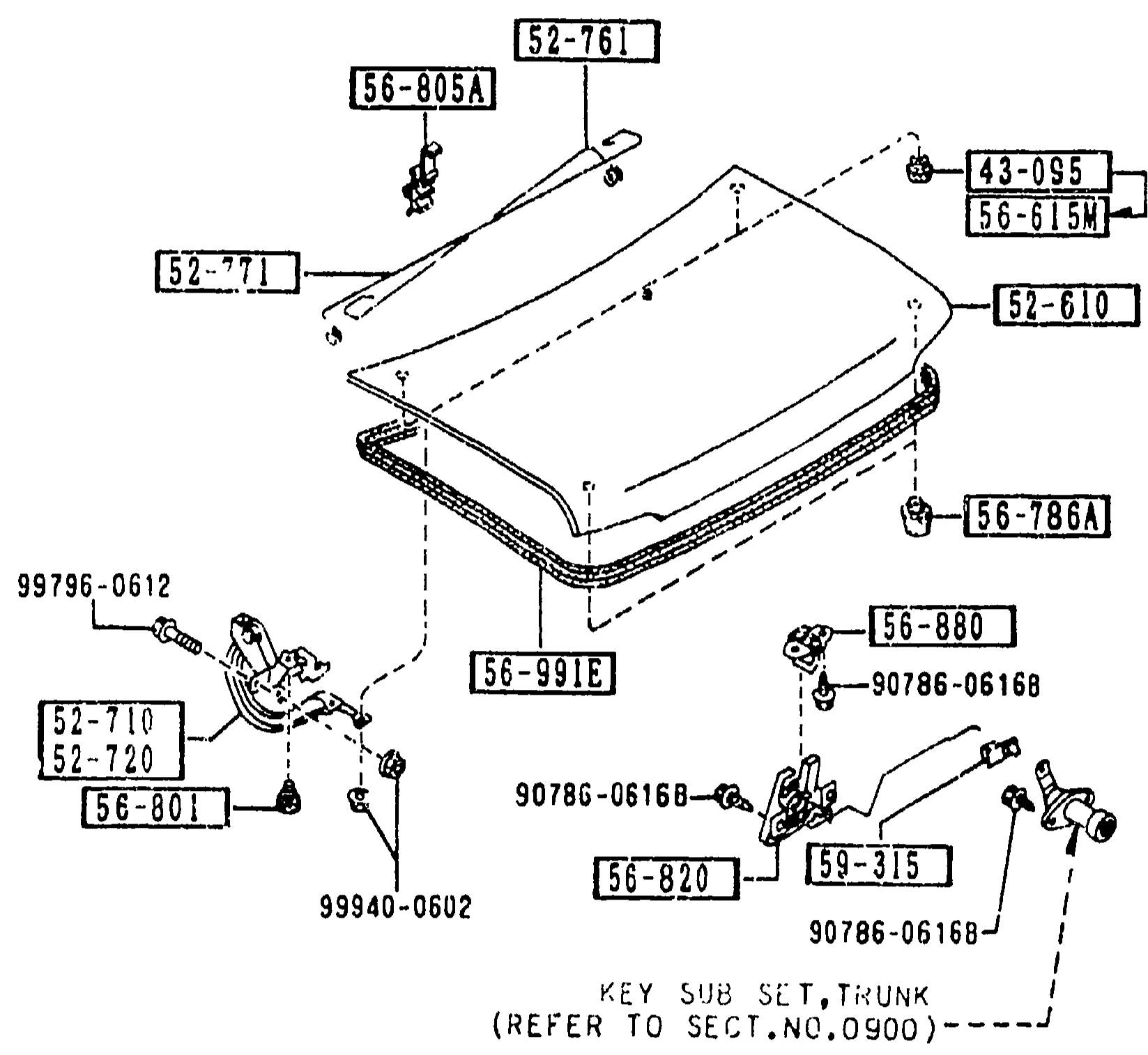
TRUNK LID
2-M 6Exploded view of the trunk lid (boot) assembly showing the lid panel [52-610], hinges (R/L) [52-710, 52-720], balance springs (R/L) [52-761, 52-771], lock [56-820], hinge cushions [56-801], rubber cushions [56-786A], drain plugs [56-615M], grommets [43-095], holder for balance spring [56-805A], weatherstrip [56-991E], and various bolts [99796-0612, 99940-0602, 90786-06168, 90786-0616B]. Key sub set reference: 'KEY SUB SET, TRUNK (REFER TO SECT.NO.0900)' near 56-820. Part numbers are shown in boxed callouts with leader lines.
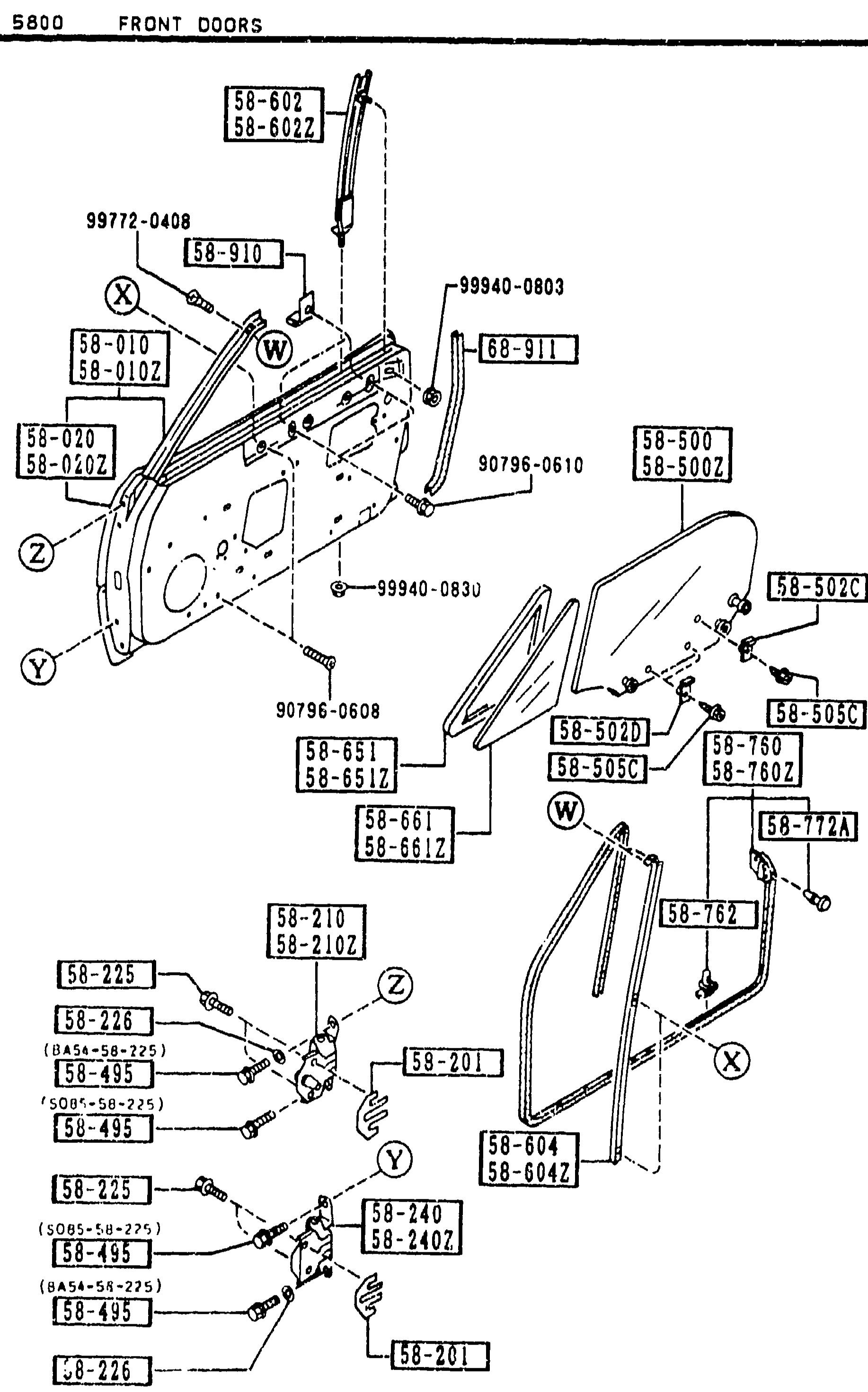
FRONT DOORS CONT'D
2-M10Same exploded view of front door assembly as the preceding page, continued. Callouts include 58-602/58-602Z (upper frame), 58-010/58-010Z (body R/L FRT door), 58-020/58-020Z (panels), 58-500/58-500Z (glass R/L), 58-502B/58-502C/58-505C (glass grommets/screws), 58-651/58-651Z (weatherstrip), 58-661/58-661Z (ventilator glass), 58-210/58-210Z (hinge upper R/L), 58-240/58-240Z (hinge lower R/L), 58-201 (shim), 58-225/58-226 (setting bolt/washer), 58-495 (bolt set), 58-72A, 58-762, 58-604/58-604Z (channel division), 58-910/58-911 (clip/bolt), 99772-0408, 99940-0803/99940-0830 (fasteners), 90796-0608/90796-0610 (bolts).
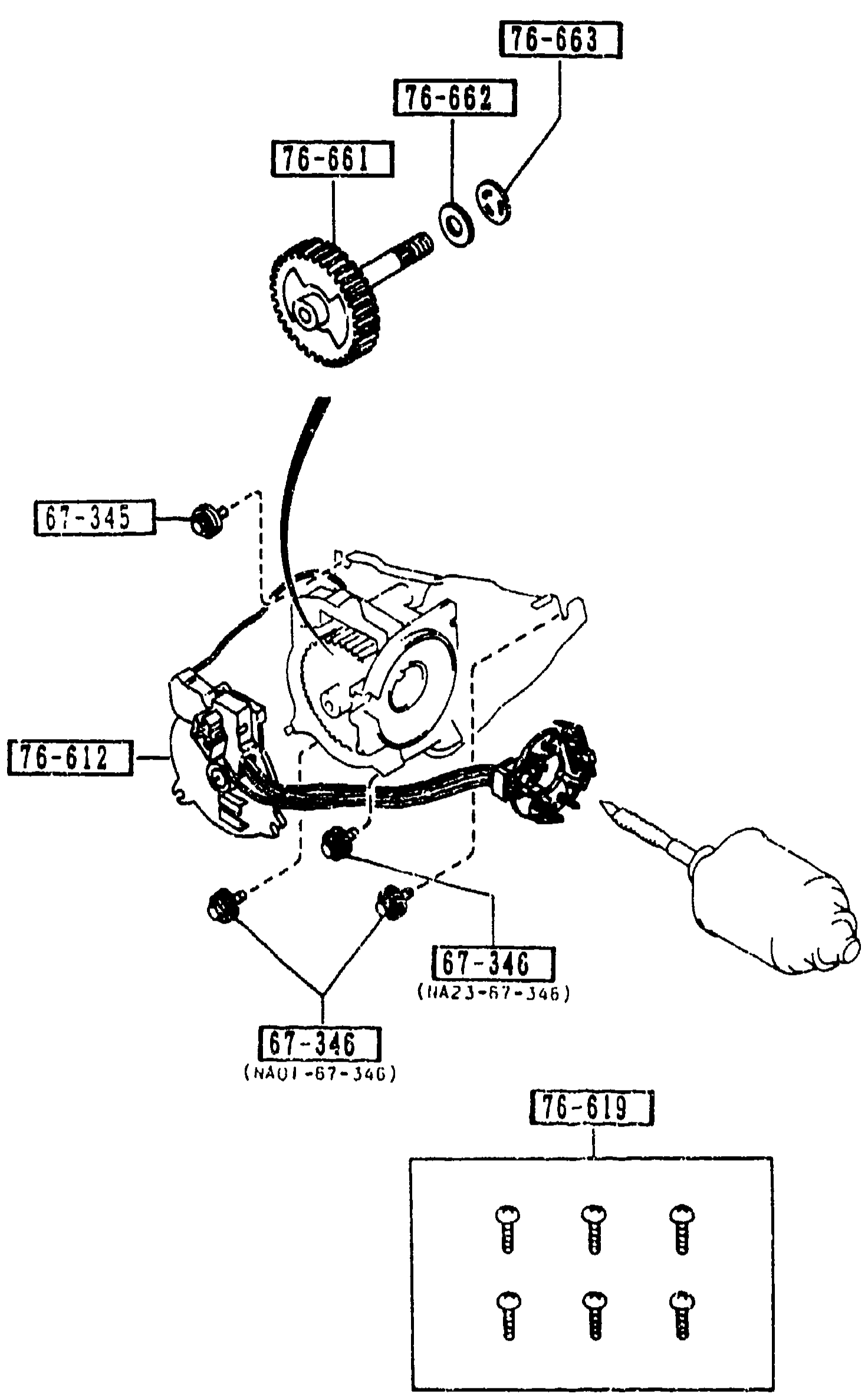
6740 WIPER MOTOR COMPONENTS (FRONT)
2-M15Exploded view of the front wiper motor internal components: gear case with the worm/output shaft, plate-brush-holder assembly, gear shaft with washer, and screws / bolts. A separate small parts grid at the bottom shows six fastener illustrations (parts set 76-619).
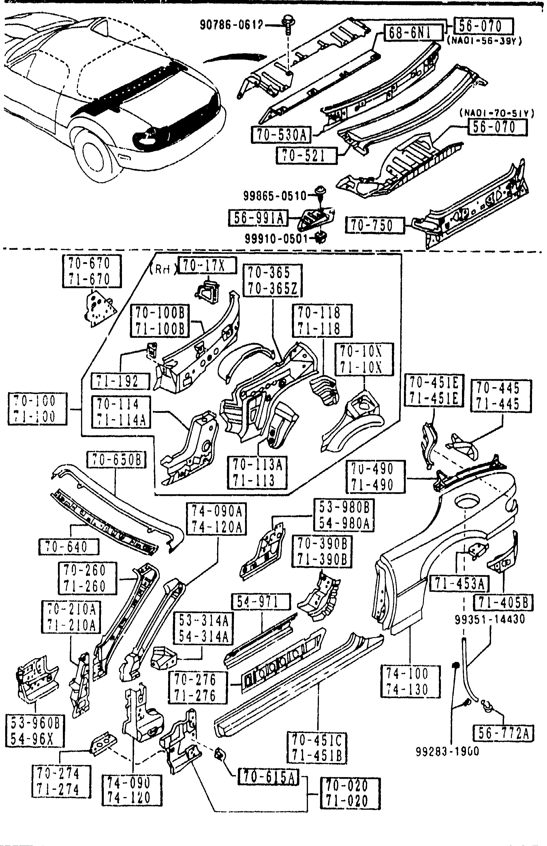
BODY PANELS (SIDE)
2-M7Continuation of the body-side exploded view (left-hand side). Top sub-diagram shows the cowl/front fender area with callouts 90786-0617, 71-128, 71-192, 71-198A (protector L splash, bracket cap-quarter pan), 71-2[?]0 (pillar hinge), 99100-0510, 99987-0501. Lower sub-diagram shows the body shell with balloons including 70-665, 71-3652, 70-100, 70-460B, 71-2705, 70-100D, 70-4516, 74-580A, 75-510A, 70-4651 (sill side out), 71-4516 (housing L lamp R fender), 71-020, 99381-14430.
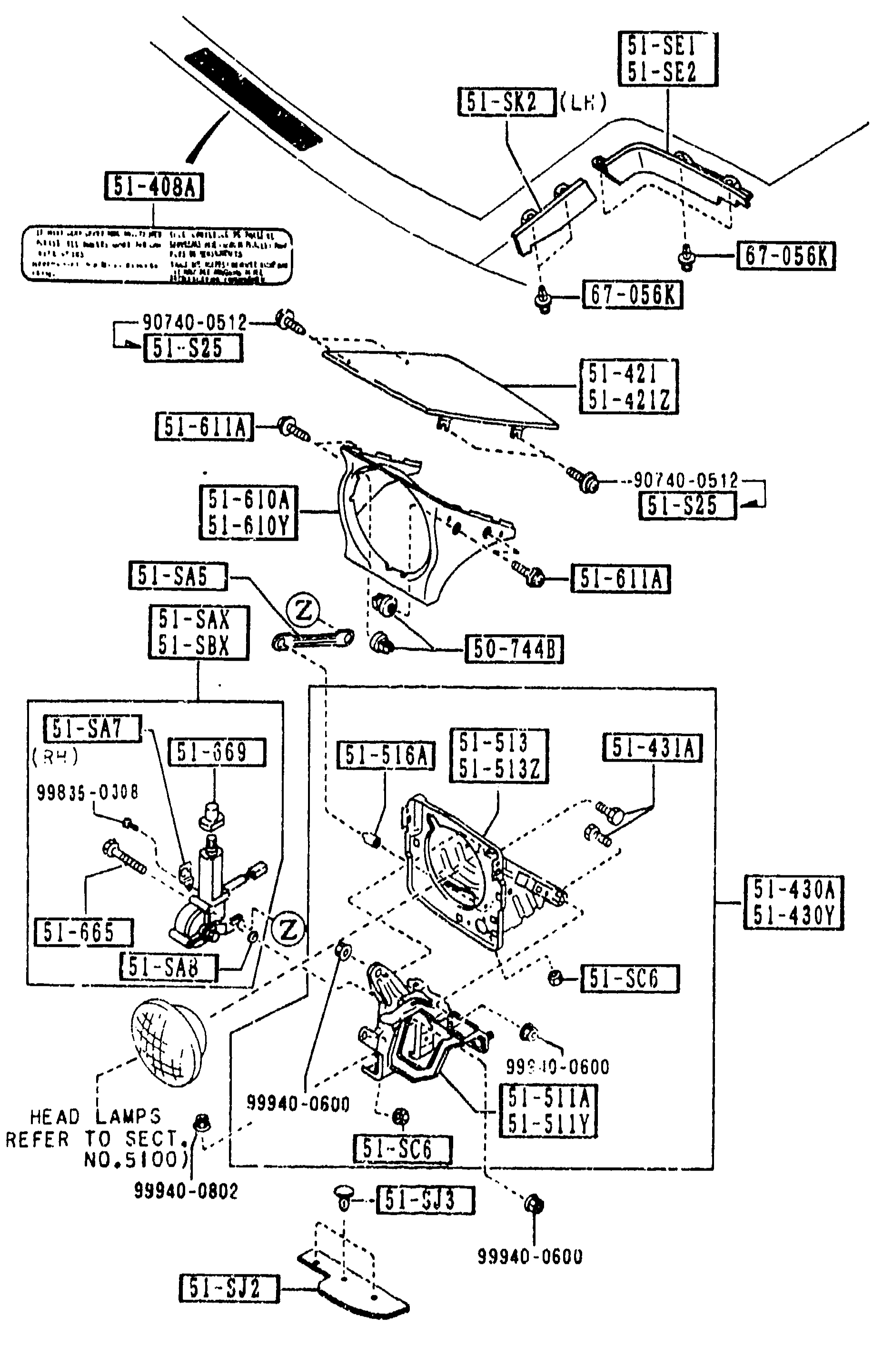
HEAD LAMP RETRACTORS (5103) — continued
2-N 5Repeat of HEAD LAMP RETRACTORS (5103) exploded view from 2-M 5: retractor caution label (51-408A), pop-up lids (51-421, 51-421Z), hinges (51-430A, 51-430Y), retractor motors R/L (51-SAX/51-SBX), pivot housings (51-513, 51-513Z), rod (51-SA5), bracket (51-SAT/SA7), washers/spacers (51-611A, 51-SA8), pivot pins/bolts (51-431A, 51-S25), spring (51-665), brackets (51-SH1A, 51-SH2A, 51-S0A, 51-SC9A, 51-SC9B, 51-SC5A, 51-SC5B, 51-SH1B, 51-SH2B), cap/hinge (51-516A). Identical drawing to previous page.
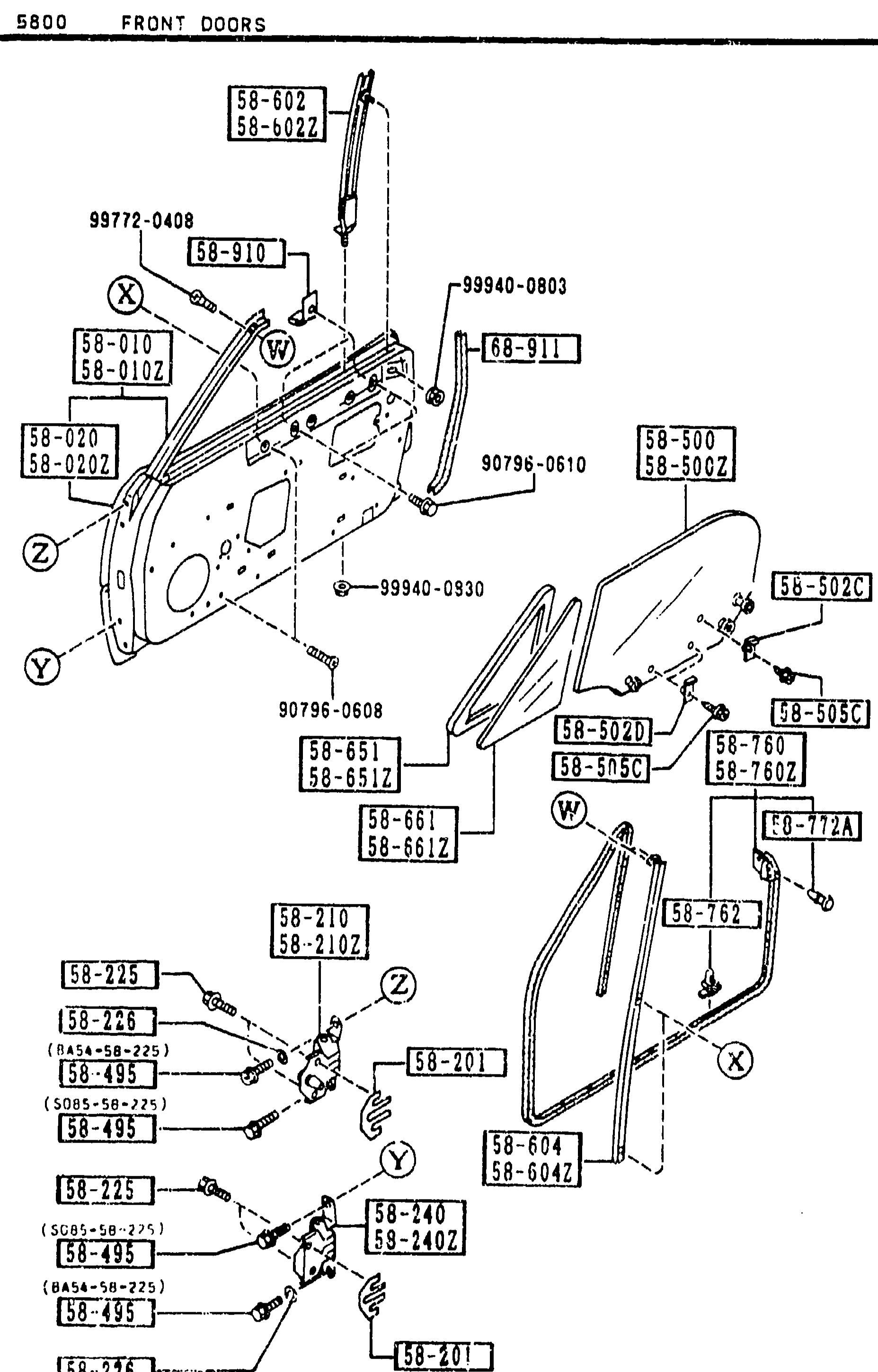
FRONT DOORS CONT'D
2-N10Identical exploded view of front door assembly repeated for the third spread of the section, focusing on weatherstrip, fastener, glass stopper and welt seaming parts. Same balloon callouts as 2-L10 / 2-M10 (door body, hinges, weatherstrips, glass, frame).
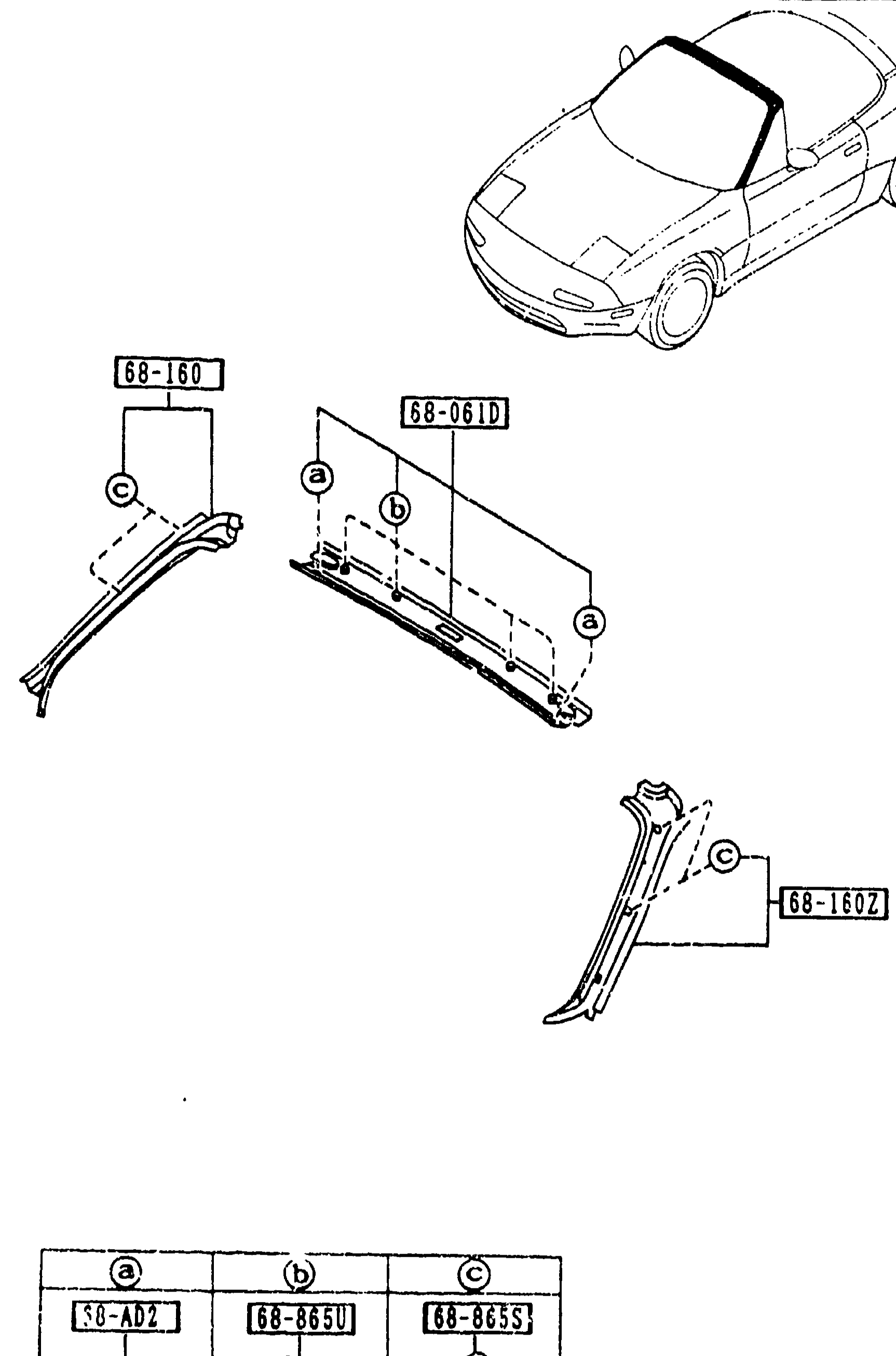
6820 FRONT HEADER TRIM & PILLAR TRIMS
2-N15Top-right vehicle context drawing shows the MX-5 with attention on the windshield header / A-pillar area. Below, three sub-figures detail the trim parts: left and right 'A' pillar trims (68-160 and 68-160Z), the front header trim (68-061D), and three small clip illustrations labelled (a)50-AD2, (b)68-865U, (c)68-865S keyed to the call letters used in the larger views.
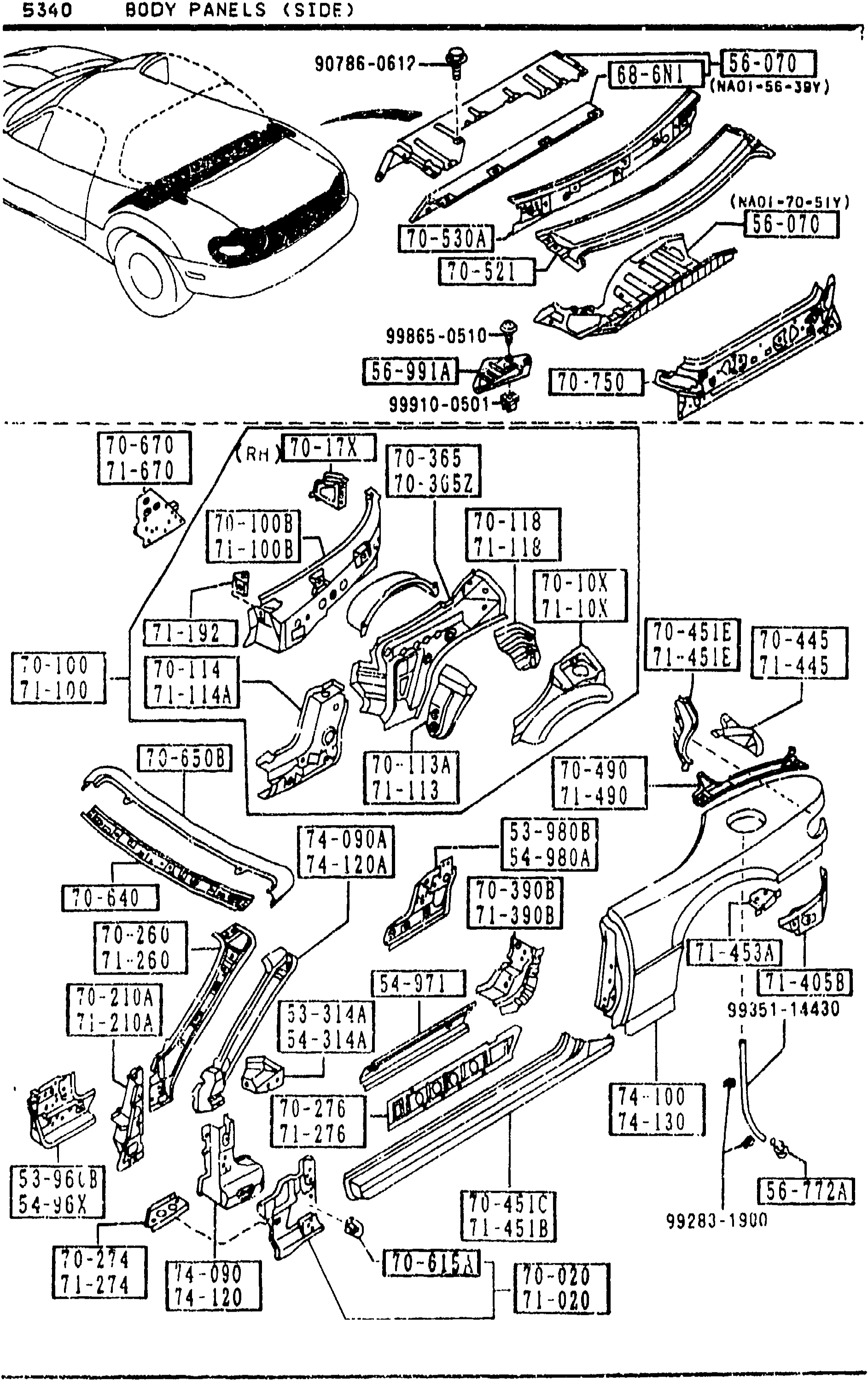
BODY PANELS (SIDE)
2-N7Exploded view of left-hand body side panels (rear and roof rail area). Top sub-diagram shows the cowl/dash area with callouts 90786-0617, 71-453, 71-453 (brkt L tr board fender), 71-440A (rail L rain rear), 71-670 (plate L closing-qtr panel), 71-090A (pillar L hinge out), 71-092A (pillar R front out). Lower sub-diagram shows the body shell side view with balloons including 71-020, 71-100, 71-100D, 71-100E, 71-114A, 71-120A, 71-450A (pillar L hinge out), 71-260, 71-460, 71-480, 75-510A, 99381-14430 fastener.
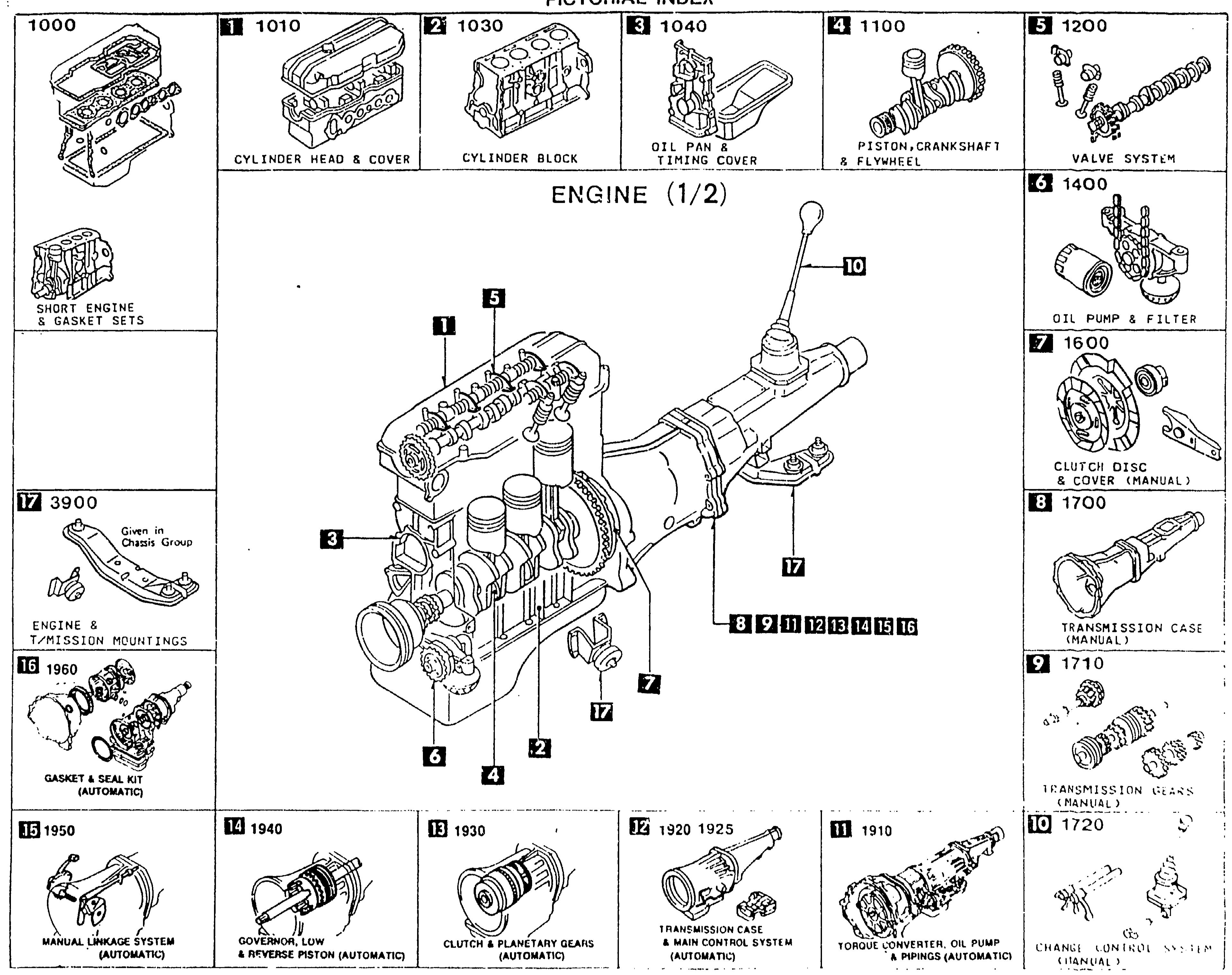
PICTORIAL INDEX — ENGINE (1/2)
3-C 1Pictorial Index: Engine (1/2). Center shows the B6 engine with manual transmission as a cutaway, with numbered callouts on each major sub-assembly. Surrounding the central illustration are 16 thumbnail boxes, each showing a sub-assembly (e.g. cylinder head & cover 1010, cylinder block 1030, oil pan & timing cover 1040, piston/crankshaft & flywheel 1100, valve system 1200, oil pump & filter 1400, clutch disc & cover (manual) 1600, transmission case (manual) 1700, transmission gears (manual) 1710, change control system (manual) 1720) along with automatic-transmission variants (1910 torque convertor, oil pump & piping; 1920/1925 transmission case & main control system; 1930 clutch & planetary gears; 1940 governor, l/m & reverse piston; 1950 manual linkage system; 1960 gasket & seal kit) plus engine & transmission mountings (3900) and short engine & gasket sets (1000).
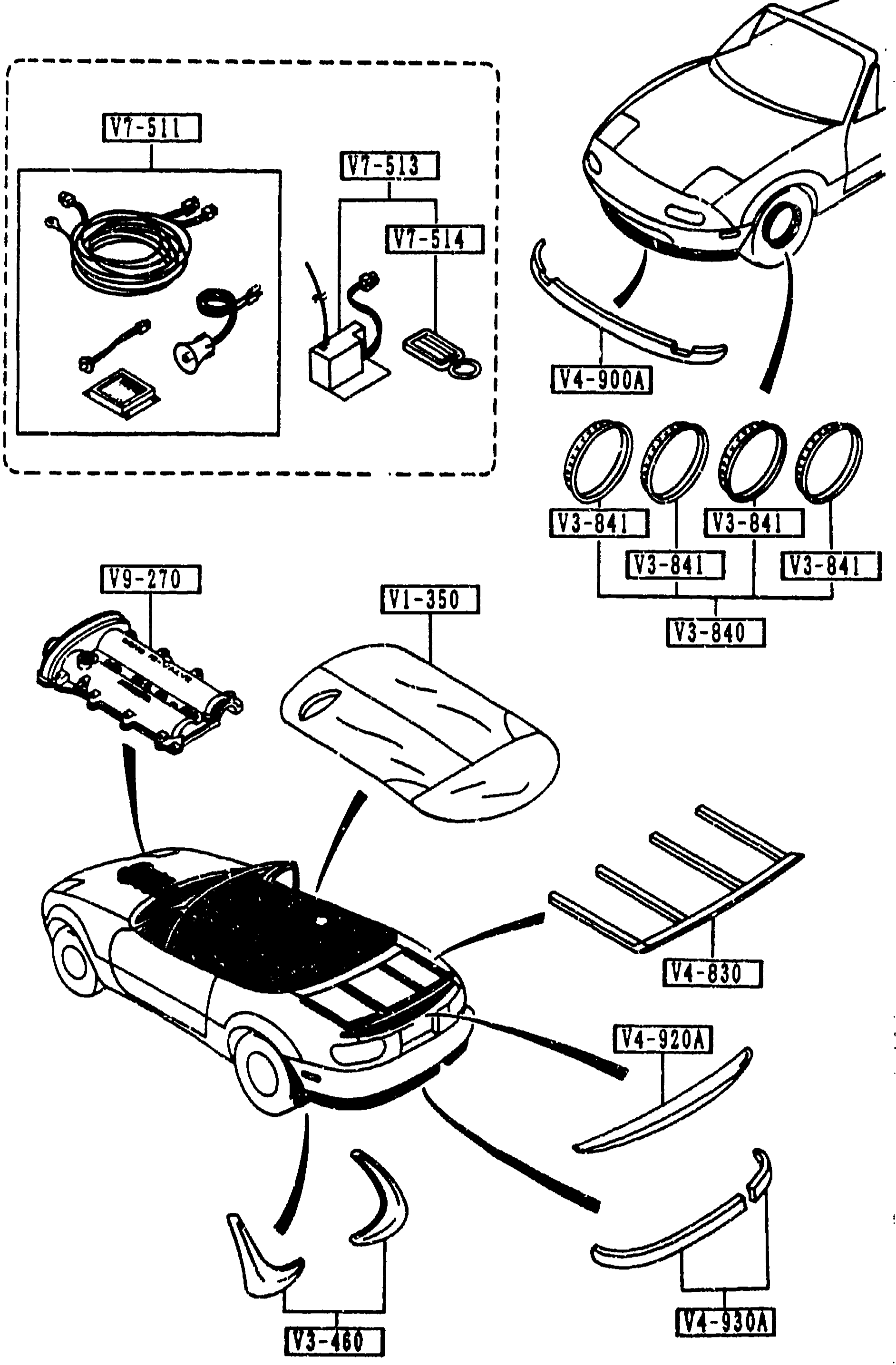
7900 ACCESSORIES
3-C 3Exploded view of MX-5 NA accessories around the body. Shows the convertible from above with callouts pointing to: V7-511 (security system module/box), V7-513 (remote upgrade kit), V7-514 (remote transmitter), V4-900A (airdam skirt, front), V3-841 (trim rings, four small rings), V3-840 (trim ring set), V4-830 (deck rack/rear spoiler bars), V9-270 (tonneau cover support), V1-350 (tonneau cover folded), V3-460 (rear-mud flap), V4-920A (rear spoiler), V4-930A (rear under skirt). The top-left dashed inset groups the security/remote items V7-511, V7-513, V7-514. The lower diagram shows the car with the various exterior trim pieces and accessories laid out around it.
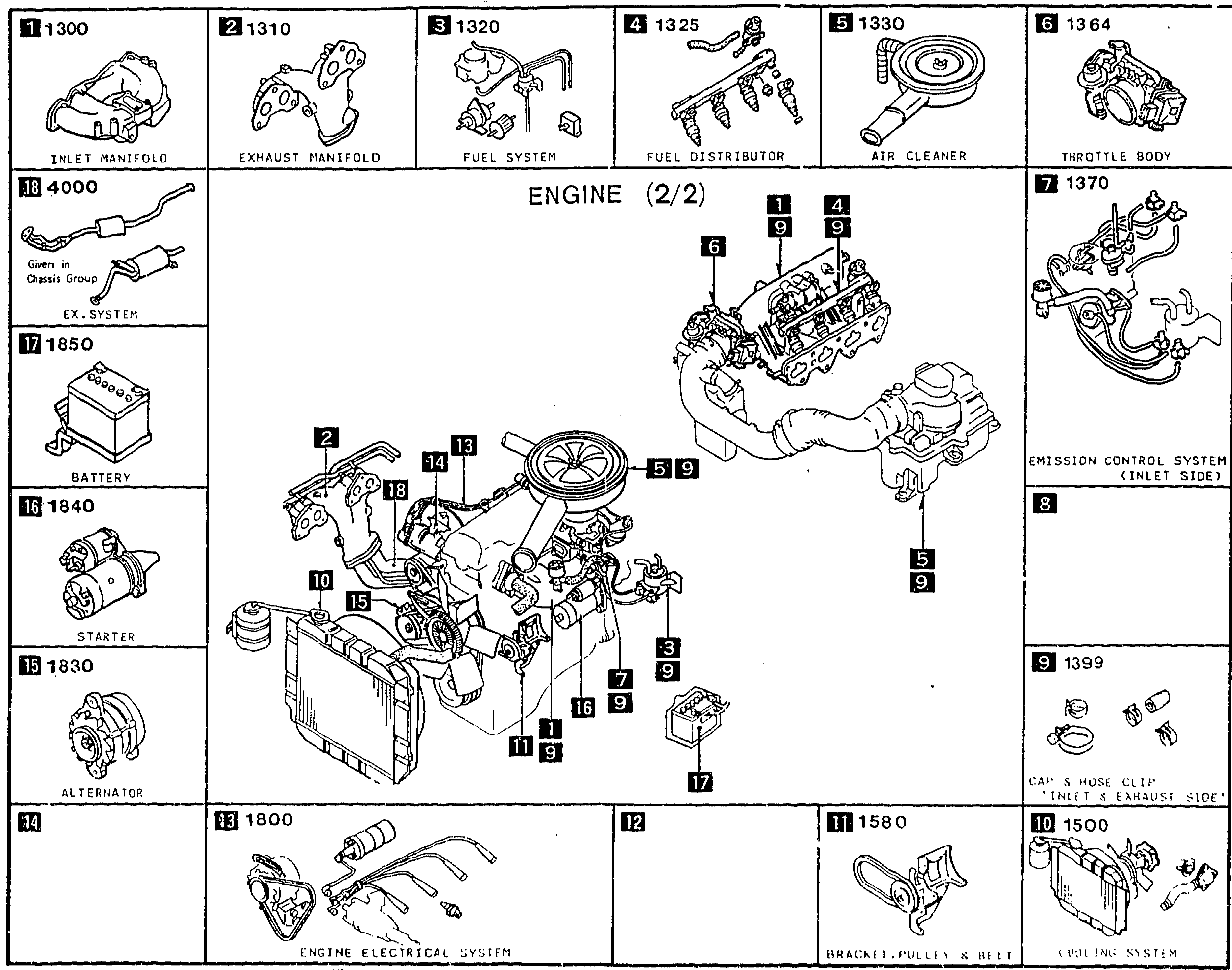
PICTORIAL INDEX — ENGINE (2/2)
3-D 1Pictorial Index: Engine (2/2). Center shows the engine viewed from the front/intake side with radiator and ancillaries. 18 numbered thumbnail boxes around the perimeter index intake-side parts groups: (1) 1300 inlet manifold, (2) 1310 exhaust manifold, (3) 1320 fuel system, (4) 1325 fuel distribution, (5) 1330 air cleaner, (6) 1364 throttle body, (7) 1370 emission control system (inlet side), (8) [emission control system inlet side overlap thumbnail], (9) 1399 cap & hose clip (inlet & exhaust side), (10) 1500 cooling system, (11) 1580 bracket, pulley & belt, (13) 1800 engine electrical system, (14) 1830 alternator, (15) 1840 starter, (16) 1850 battery, (17) 1860 ex.system (located on chassis group), (18) 4000 ex.system. Numbered callouts on the central engine illustration tie back to each thumbnail.
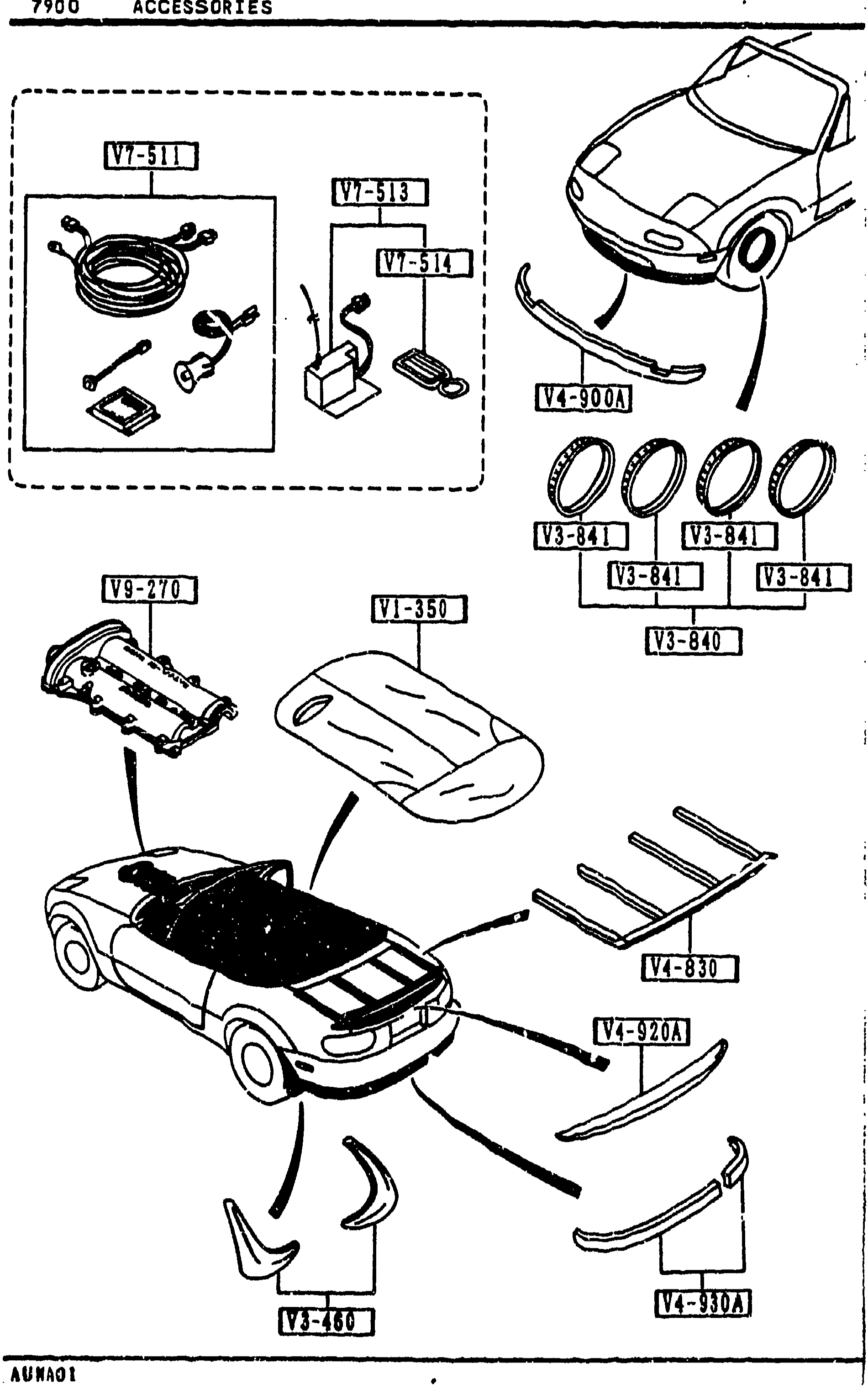
7900 ACCESSORIES
3-D 3Same MX-5 NA accessories exploded view as the facing page (3-C 3): dashed inset top-left containing V7-511 security harness, V7-513 remote upgrade kit, V7-514 remote transmitter. Body of page shows V4-900A airdam skirt (front), four V3-841 trim rings + V3-840 trim ring set, V9-270 valve cover/tonneau support, V1-350 tonneau cover, V4-830 deck rack, V4-920A rear spoiler, V4-930A rear under skirt, V3-460 rear-mud flap. Same illustration is reused so the V9-270 chrome valve cover (listed in the table on this page) is depicted in the same V9-270 position.
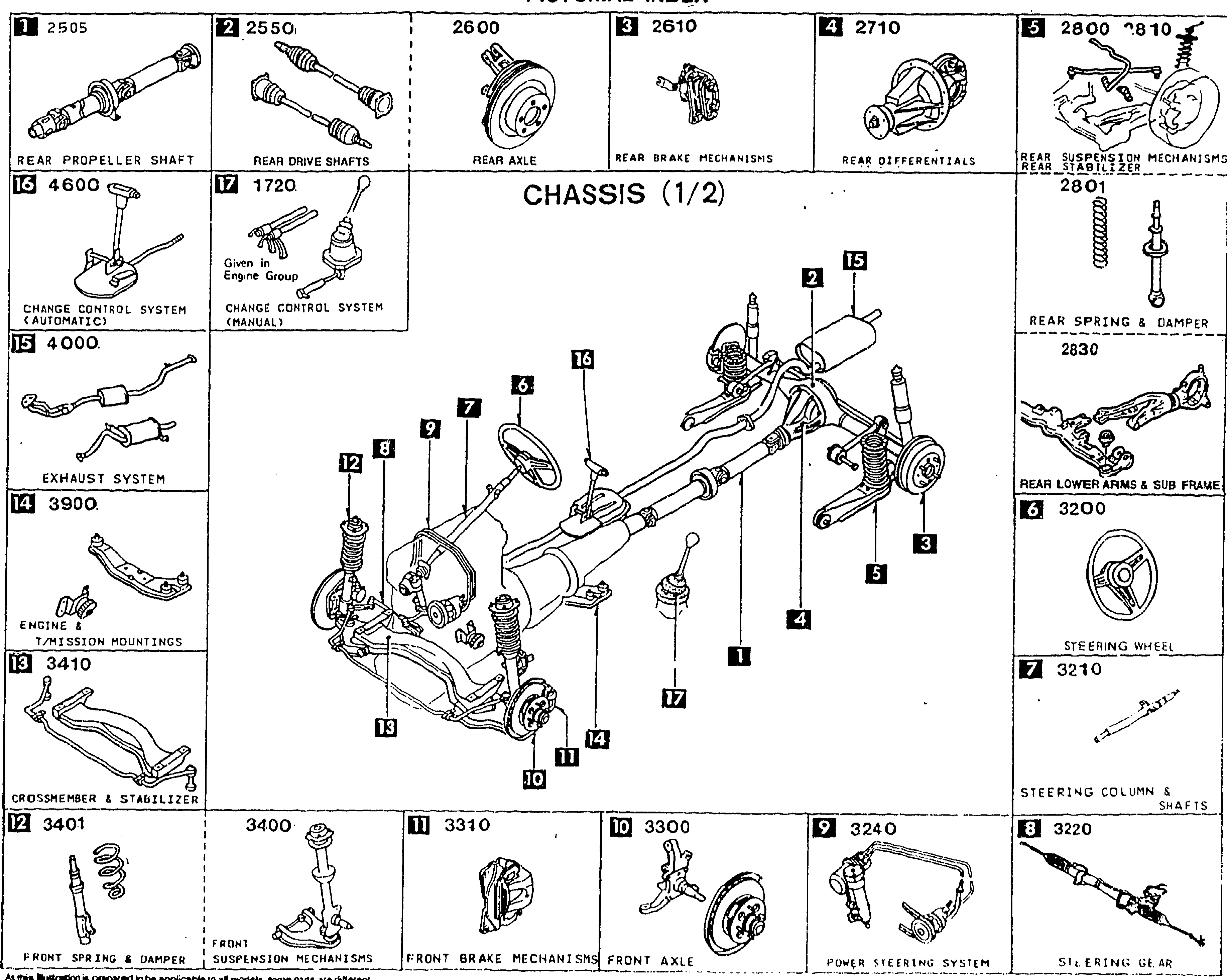
PICTORIAL INDEX — CHASSIS (1/2)
3-E 1Pictorial index for CHASSIS (1/2). Center shows a 3/4 overhead exploded view of the rear-driveline & suspension cluster (propeller shaft, rear axle, differential, rear suspension, exhaust, steering column, etc.) with numbered balloon callouts 1–17. Around the perimeter, thumbnail panels label each major sub-assembly with its section number: 1) 2505 REAR PROPELLER SHAFT, 2) 2550 REAR DRIVE SHAFTS, 2600 REAR AXLE, 3) 2610 REAR BRAKE MECHANISMS, 4) 2710 REAR DIFFERENTIALS, 5) 2800/2810 REAR SUSPENSION MECHANISMS, 2801 REAR SPRING & DAMPER, 2830 REAR LOWER ARMS & SUB FRAME, 7) 3200 STEERING WHEEL, 7) 3210 STEERING COLUMN & SHAFTS, 8) 3220 STEERING GEAR, 9) 3240 POWER STEERING SYSTEM, 10) 3300 FRONT AXLE, 11) 3310 FRONT BRAKE MECHANISMS, 3400 FRONT SUSPENSION MECHANISMS, 12) 3401 FRONT SPRING & DAMPER, 13) 3410 CROSSMEMBER & STABILIZER, 14) 3900 ENGINE & T/MISSION MOUNTINGS, 15) 4000 EXHAUST SYSTEM, 16) 4600 CHANGE CONTROL SYSTEM (AUTOMATIC), 1720 CHANGE CONTROL SYSTEM (MANUAL). Each thumbnail shows a small line drawing of the corresponding part.
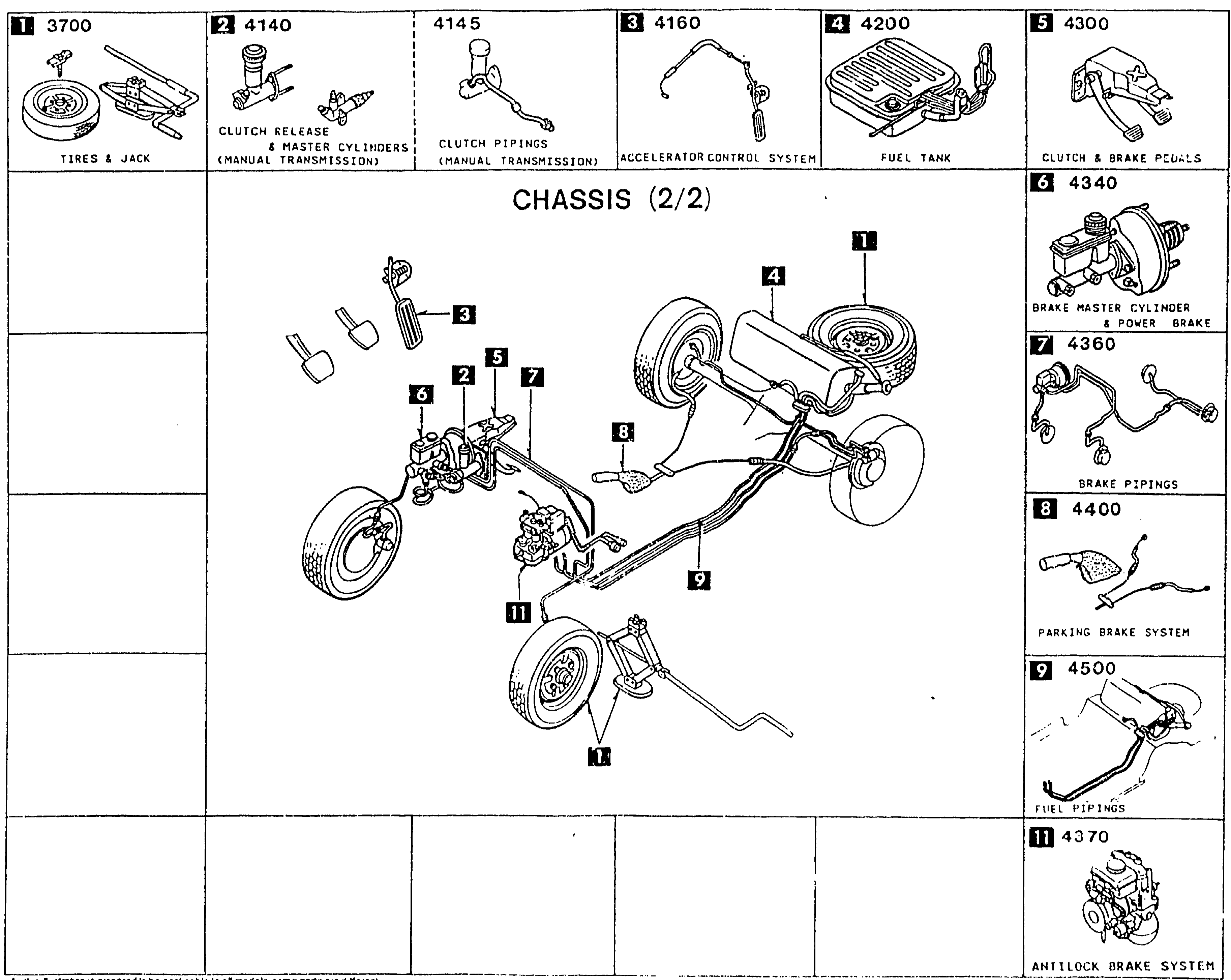
PICTORIAL INDEX — CHASSIS (2/2)
3-F 1Pictorial index for CHASSIS (2/2). Center shows a 3/4 overhead exploded view of the vehicle highlighting the fuel tank, brake/clutch piping routing, brake mechanisms and clutch master/release cylinders with numbered balloon callouts 1–11. Around the perimeter, thumbnail panels label each sub-assembly with its section number: 1) 3700 TIRES & JACK, 2) 4140 CLUTCH RELEASE & MASTER CYLINDERS (MANUAL TRANSMISSION), 4145 CLUTCH PIPINGS (MANUAL TRANSMISSION), 3) 4160 ACCELERATOR CONTROL SYSTEM, 4) 4200 FUEL TANK, 5) 4300 CLUTCH & BRAKE PEDALS, 6) 4340 BRAKE MASTER CYLINDER & POWER BRAKE, 7) 4360 BRAKE PIPINGS, 8) 4400 PARKING BRAKE SYSTEM, 9) 4500 FUEL PIPINGS, 11) 4370 ANTILOCK BRAKE SYSTEM.
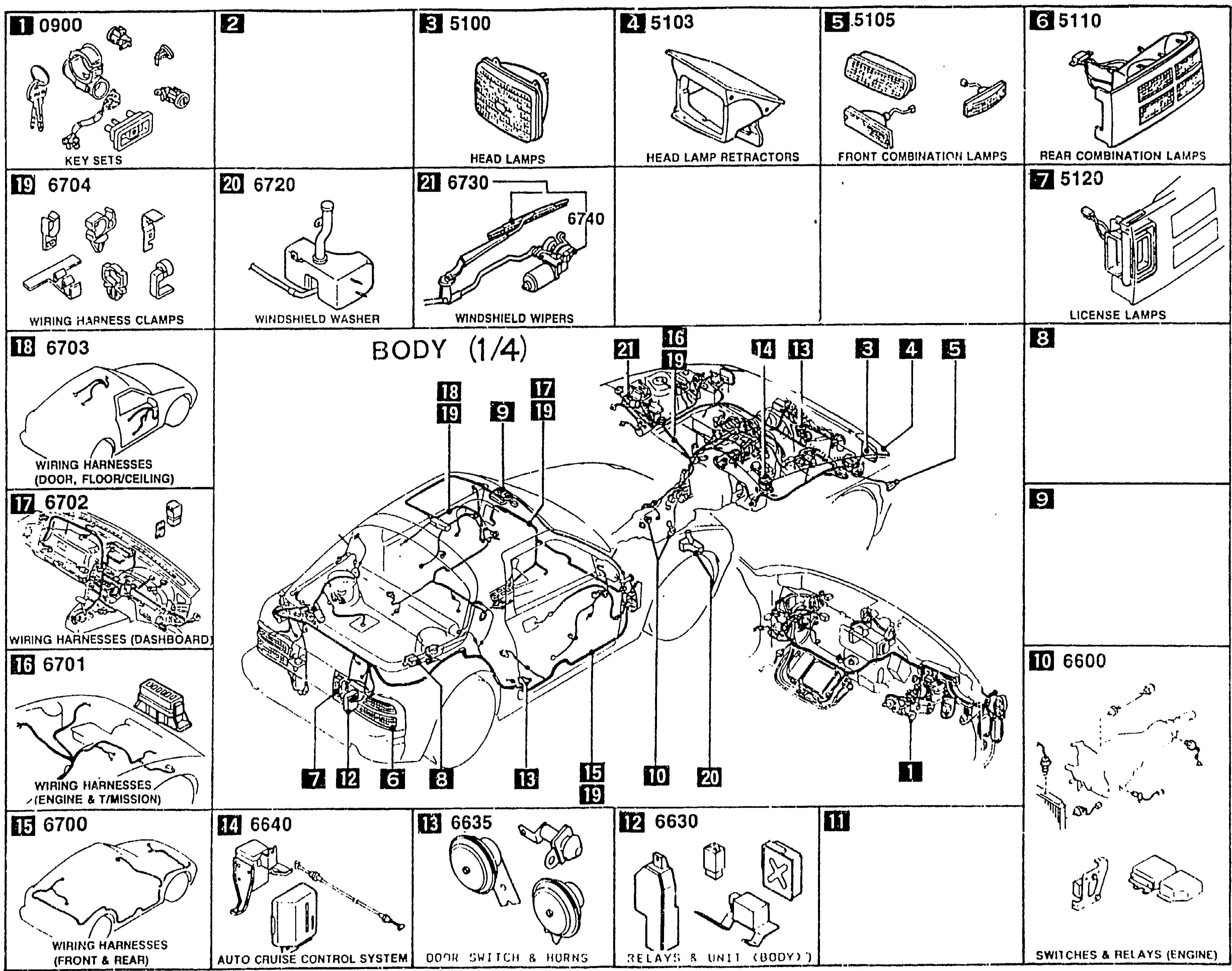
PICTORIAL INDEX — BODY (1/4)
3-G 1Pictorial index for BODY (1/4). Center shows a 3/4 overhead exploded view of the body shell with wiring harness routing and lamp locations highlighted, numbered balloons 1–21. Perimeter thumbnails: 1) 5500 DASHBOARD EQUIPMENTS (per Body 3/4 cross-section — wait, this is Body 1/4: actually 5500 lists head-lamps area), 1) 5500 HEAD LAMPS, 2) 5520 HEAD LAMP RETRACTORS, 3) 5530 FRONT COMBINATION LAMPS, 4) 5540 REAR COMBINATION LAMPS, 5) 5560 LICENSE LAMPS, 6) 5570; corrected reading: 1) 0900 KEY SETS, 2) 5520 (blank middle), 3) 5100 HEAD LAMPS, 4) 5103 HEAD LAMP RETRACTORS, 5) 5105 FRONT COMBINATION LAMPS, 6) 5110 REAR COMBINATION LAMPS, 7) 5120 LICENSE LAMPS, 10) 6600 SWITCHES & RELAYS (ENGINE), 11) (blank middle), 12) 6630 RELAYS & UNIT (BODY), 13) 6635 DOOR SWITCH & HORNS, 14) 6640 AUTO CRUISE CONTROL SYSTEM, 15) 6700 WIRING HARNESSES (FRONT & REAR), 16) 6701 WIRING HARNESSES (ENGINE & T/MISSION), 17) 6702 WIRING HARNESSES (DASHBOARD), 18) 6703 WIRING HARNESSES (DOOR, FLOOR/CEILING), 19) 6704 WIRING HARNESS CLAMPS, 20) 6720 WINDSHIELD WASHER, 21) 6730 WINDSHIELD WIPERS, 6740 WIPER MOTOR COMPONENTS (FRONT).
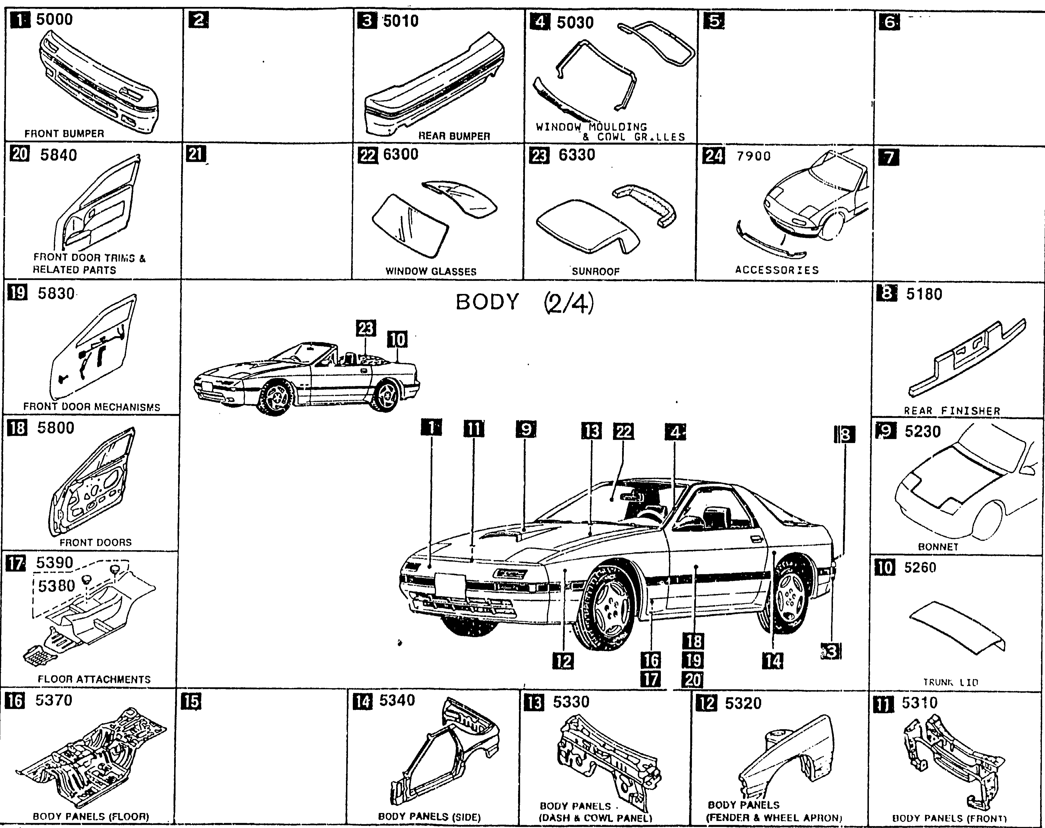
PICTORIAL INDEX — BODY (2/4)
3-H 1Pictorial index for BODY (2/4). Center shows a 3/4 view of the vehicle exterior (sports coupe body — front and side perspective) with numbered balloons 1–24 identifying bumpers, panels, door mechanisms, body panels and accessories. Perimeter thumbnail panels: 1) 5000 FRONT BUMPER, 3) 5010 REAR BUMPER, 4) 5030 WINDOW MOULDING & COWL GRILLES, 8) 5180 REAR FINISHER, 9) 5230 BONNET, 10) 5260 TRUNK LID, 11) 5310 BODY PANELS (FRONT), 12) 5320 BODY PANELS (FENDER & WHEEL APRON), 13) 5330 BODY PANELS (DASH & COWL PANEL), 14) 5340 BODY PANELS (SIDE), 16) 5370 BODY PANELS (FLOOR), 17) 5380/5390 FLOOR ATTACHMENTS, 18) 5800 FRONT DOORS, 19) 5830 FRONT DOOR MECHANISMS, 20) 5840 FRONT DOOR TRIMS & RELATED PARTS, 22) 6300 WINDOW GLASSES, 23) 6330 SUNROOF, 24) 7900 ACCESSORIES.
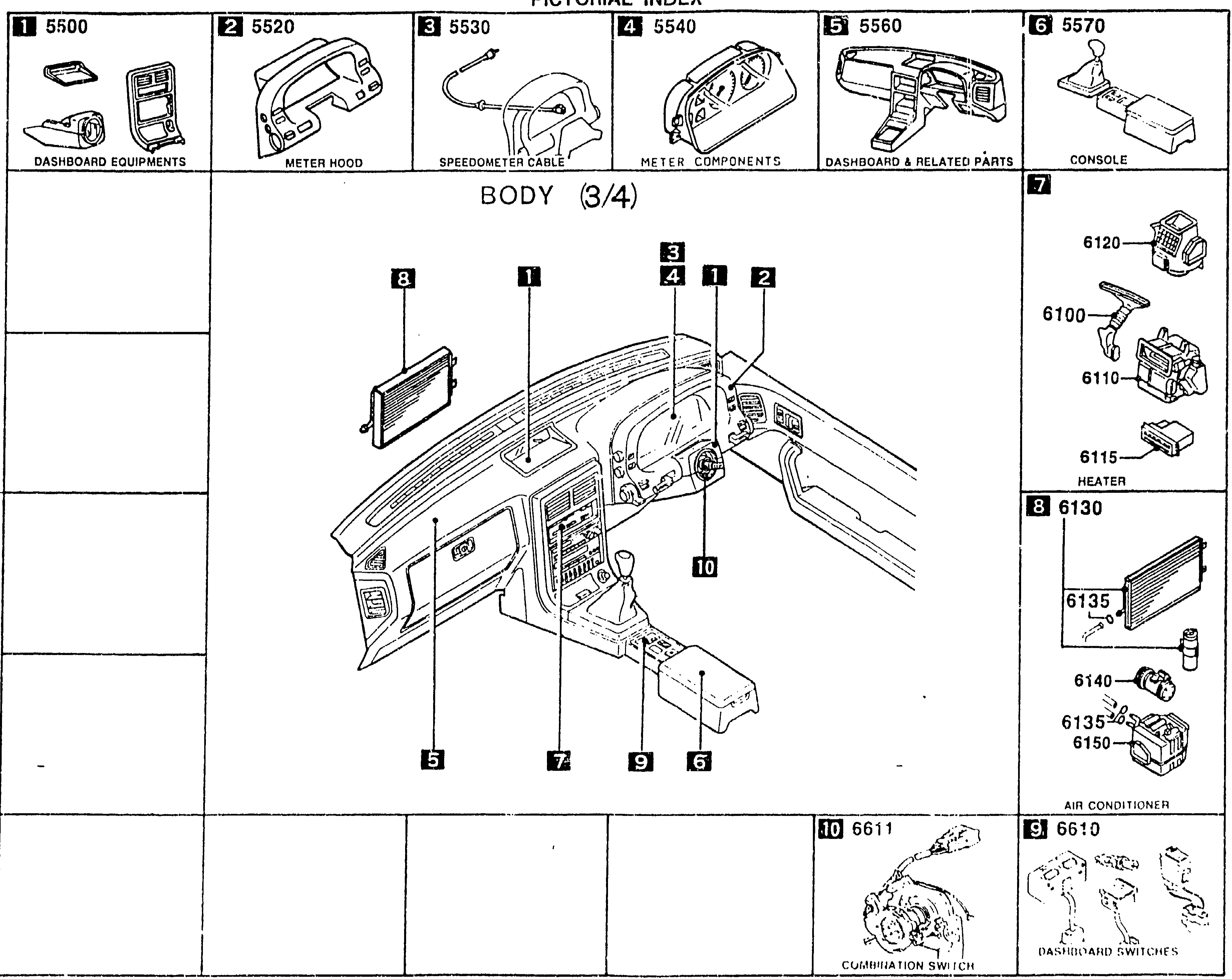
PICTORIAL INDEX — BODY (3/4)
3-i 1Pictorial index for BODY (3/4). Center shows a 3/4 interior view of the dashboard / instrument panel / center console with numbered balloons 1–10 identifying dashboard sub-assemblies. Perimeter thumbnails: 1) 5500 DASHBOARD EQUIPMENTS, 2) 5520 METER HOOD, 3) 5530 SPEEDOMETER CABLE, 4) 5540 METER COMPONENTS, 5) 5560 DASHBOARD & RELATED PARTS, 6) 5570 CONSOLE, 7) 6100 HEATER (6120 / 6110 / 6115), 8) 6130 AIR CONDITIONER (6135 / 6140 / 6150), 9) 6610 DASHBOARD SWITCHES, 10) 6611 COMBINATION SWITCH.
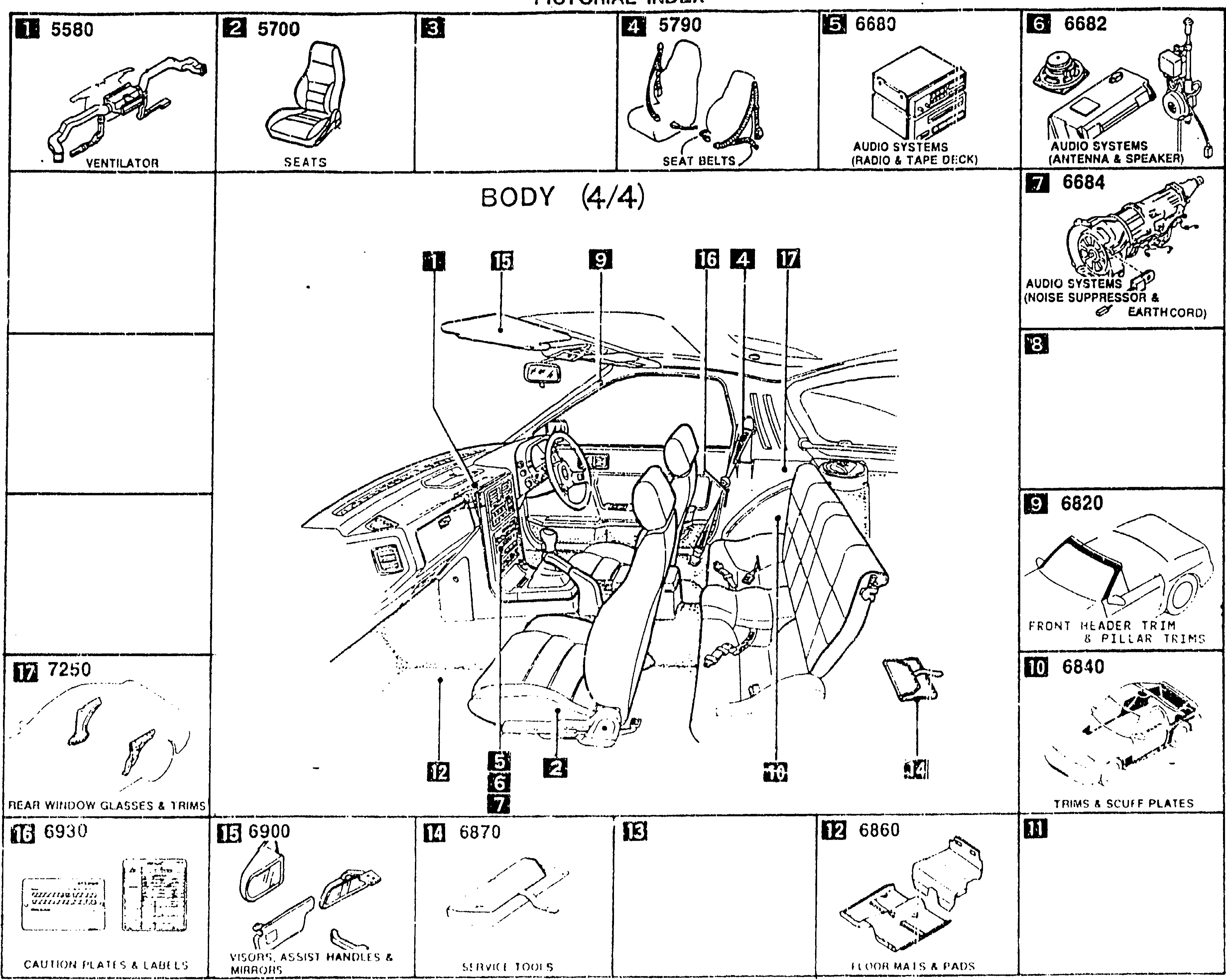
PICTORIAL INDEX — BODY (4/4)
3-J 1Pictorial index for BODY (4/4). Center shows a 3/4 interior view from the driver-side door opening looking across at the dashboard, seats, steering wheel and rear quarter trim, with numbered balloons 1–17 identifying interior sub-assemblies. Perimeter thumbnails: 1) 5580 VENTILATOR, 2) 5700 SEATS, 4) 5790 SEAT BELTS, 5) 6680 AUDIO SYSTEMS (RADIO & TAPE DECK), 6) 6682 AUDIO SYSTEMS (ANTENNA & SPEAKER), 7) 6684 AUDIO SYSTEMS (NOISE SUPPRESSOR & EARTH CORD), 9) 6820 FRONT HEADER TRIM & PILLAR TRIMS, 10) 6840 TRIMS & SCUFF PLATES, 12) 6860 FLOOR MATS & PADS, 13) (blank), 14) 6870 SERVICE TOOLS, 15) 6900 VISORS, ASSIST HANDLES & MIRRORS, 16) 6930 CAUTION PLATES & LABELS, 17) 7250 REAR WINDOW GLASSES & TRIMS.