
MANUAL STEERING
N-12parts diagramU.S. spec. air-bag-equipped models require clockspring connector adjustment if pinion shaft is disconnected away from straight-ahead position.
STEERING GEAR AND LINKAGE
Removal / Installation
CAUTION
Disconnect/connect the pinion shaft from/to the intermediate shaft with the wheels in the straight-ahead position, and do not turn the steering wheel while the steering gear is removed. If not done correctly, adjust the clockspring connector. (U.S. spec.) (Refer to Section T.)
Removal / Installation
- 1Loosen the wheel lug nuts.
- 2Jack up the front of the vehicle and support it with safety stands.
- 3Remove the wheel.
- 4Remove the undercover.
- 5Remove in the order shown in the figure, referring to Removal Note.
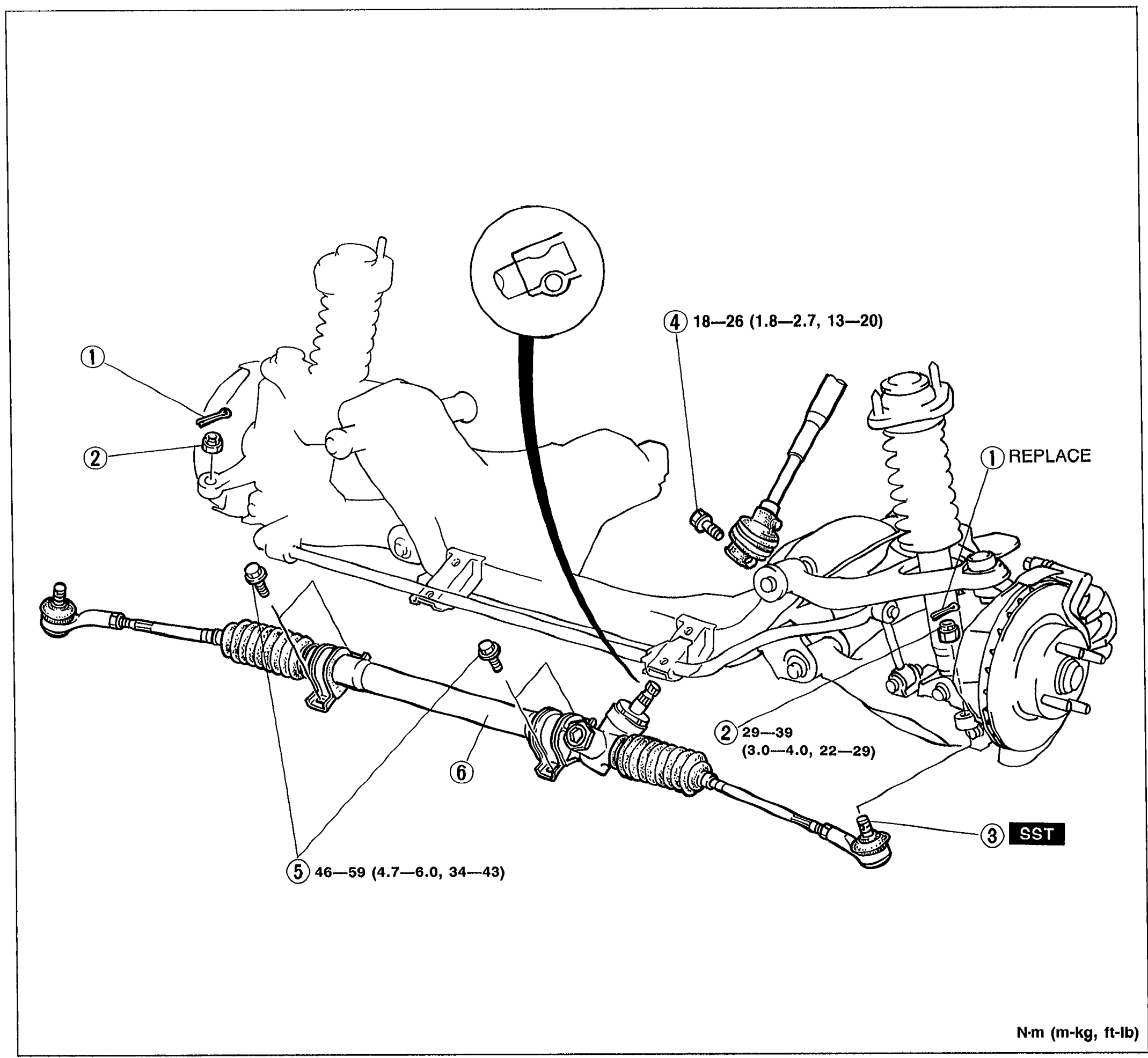 05U0NX-020
 - 6Install in the reverse order of removal.
Parts DiagramFig. fig1