Mazda MX-5 NA silhouetteMX-5 NA

MANUAL STEERING

N-9parts diagram

U.S. spec. models include air bag; non-U.S. versions use horn pad without air bag. Two variants shown in diagram.

Removal / Installation

Removal / Installation

  1. 1
    Disconnect the negative battery cable.
  2. 2
    Remove in the order shown in the figure, referring to Removal Note.
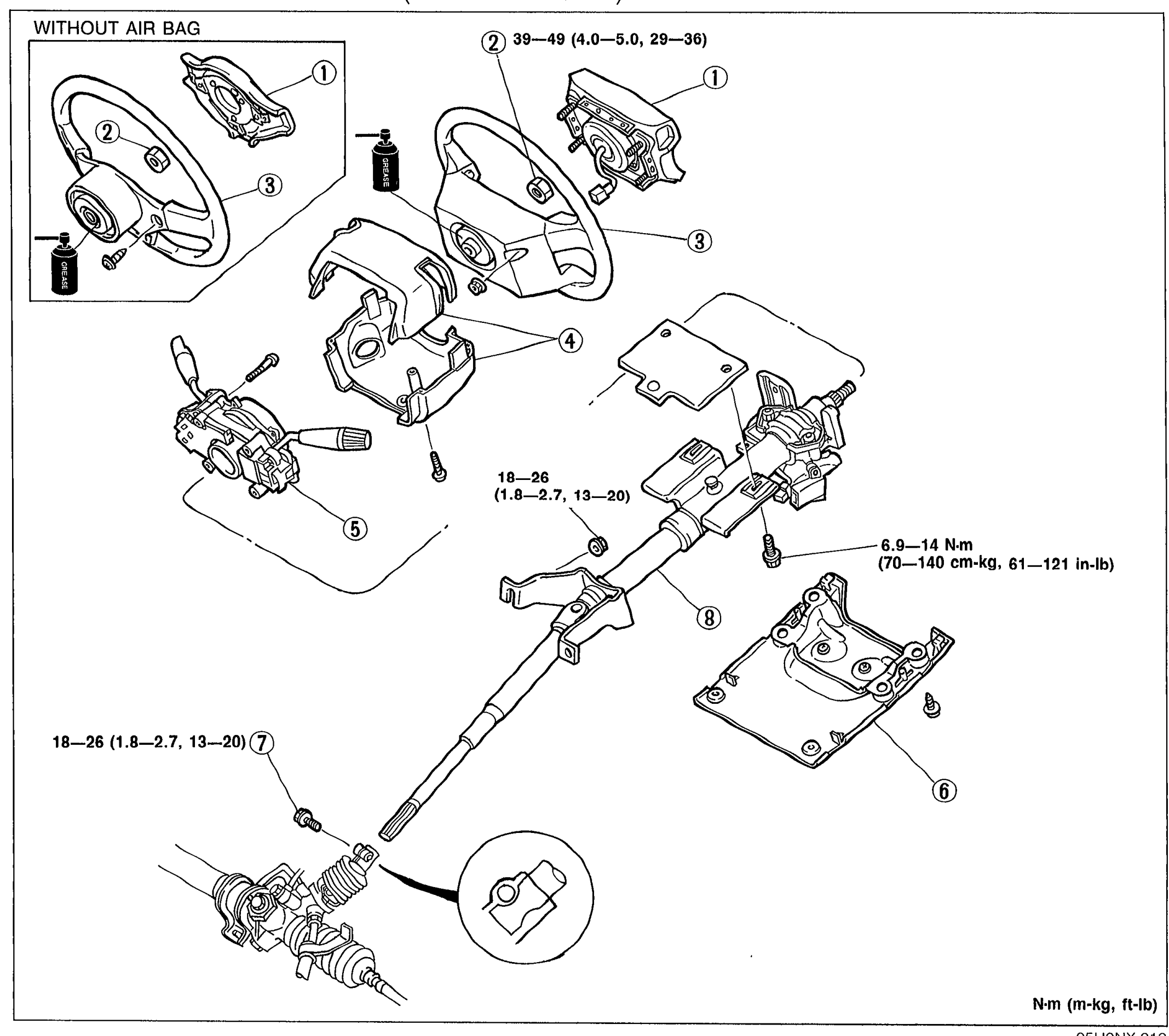
    Exploded view of the steering wheel and column assembly (WITHOUT AIR BAG version on the left). Shows balloon callouts 1–8 for: air bag module, horn pad, locknut, steering wheel, column cover, lower panel, intermediate shaft bolt, and steering shaft. Torque specifications annotated next to fasteners: 39—49 N·m at the top retaining nut, 18—26 N·m at the upper steering shaft bolt and at the lower shaft bolt (callout 7), and 6.9—14 N·m at the column mounting bracket bolts. A small detail view at the bottom-right shows the intermediate shaft U-joint orientation.
    05U0NX-013
  3. 3
    Install in the reverse order of removal.
  4. 4
    Tighten all necessary nuts and bolts to the specified torque.
  5. 5
    After installation, check if the horn sounds. If the horn does not sound, remove the air bag module and connect the module connectors. (Refer to Section T.)
Parts DiagramFig. fig1
#Part NameNotes
1Air bag moduleRemoval / Installation .... Section T
1Horn pad (without air bag)
2LocknutTightening torque: 39—49 N·m (4.0—5.0 m-kg, 29—36 ft-lb)
3Steering wheelRemoval Note .... page N-10
4Column cover
5Combination switchRemoval / Installation .... Section T; Tightening torque: 18—26 N·m (1.8—2.7 m-kg, 13—20 in-lb)
6Lower panelTightening torque: 6.9—14 N·m (70—140 cm-kg, 61—121 in-lb)
7Intermediate shaft boltTightening torque: 18—26 N·m (1.8—2.7 m-kg, 13—20 in-lb)
8Steering shaftDisassembly / Inspection / Assembly .... page N-10

See also

Search Manual

Search pages, specs, and procedures