Mazda MX-5 NA silhouetteMX-5 NA

MANUAL STEERING

N-6parts diagram

BOOT

Replacement

Boot Replacement

  1. 1
    Loosen the wheel lug nuts.
  2. 2
    Jack up the front of the vehicle and support it with safety stands.
  3. 3
    Remove the wheel.
  4. 4
    Remove in the order shown in the figure, referring to Removal Note.
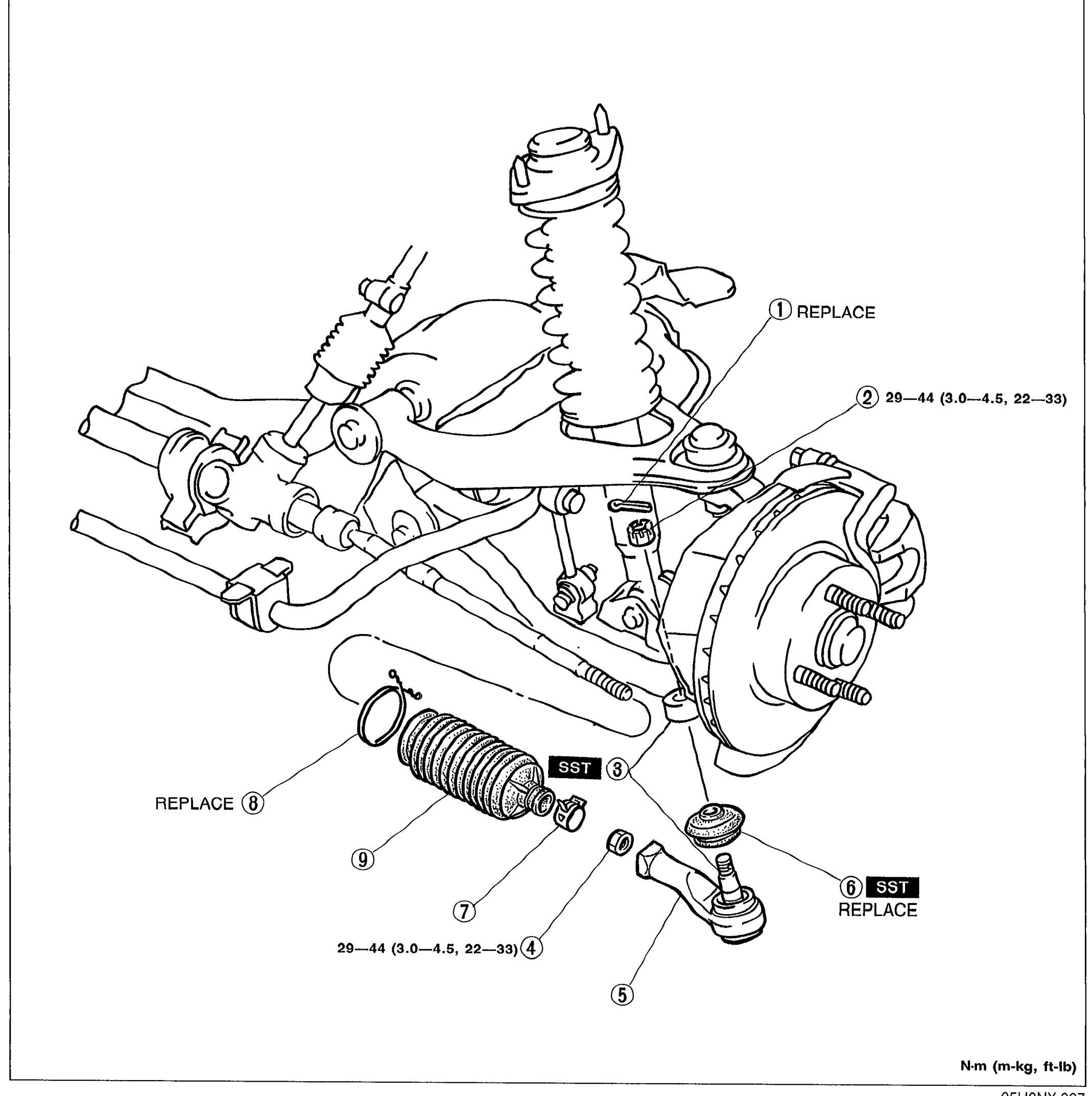
    Exploded view of the steering boot and tie-rod end assembly attached to the steering knuckle/front suspension. Shows the strut/spring, brake rotor, steering knuckle, and the tie-rod with boot, locknut, and ball-end. Numbered balloon callouts 1-9 identify components for replacement/disassembly. Notes: '1 REPLACE' label near top, '2 29—44 (3.0—4.5, 22—33)' torque for nut, '3 SST' indicating SST use at one point, '4 29—44 (3.0—4.5, 22—33)' torque for tie-rod, '6 SST REPLACE', '8 REPLACE' near boot, and 'N·m (m-kg, ft-lb)' units legend bottom-right.
    05U0NX-007
  5. 5
    Install in the reverse order of removal, referring to Installation Note.
  6. 6
    After installation, check the steering angle and toe-in and adjust if necessary. (Refer to Section R.)
Parts DiagramFig. fig1
#Part NameNotes
1Cotter pinREPLACE
2NutTightening torque: 29—44 N·m (3.0—4.5 m-kg, 22—33 ft-lb)
3Tie-rod end / Steering knuckleRemoval Note ... page N-7; SST required
4LocknutRemoval Note ... page N-7; Tightening torque: 29—44 N·m (3.0—4.5 m-kg, 22—33 ft-lb)
5Tie-rod end
6Tie-rod end bootRemoval / Installation Note ... page N-7; SST required; REPLACE
7Boot clamp
8Boot wireREPLACE
9Steering gear boot

See also

Search Manual

Search pages, specs, and procedures