
ENGINE SPEED SENSING POWER STEERING — STEERING GEAR AND LINKAGE
N-19parts diagramU.S. spec — clockspring connector adjustment if intermediate shaft disconnected with wheels not in straight-ahead position.
STEERING GEAR AND LINKAGE
Removal / Installation
CAUTION
Disconnect/connect the pinion shaft from/to the intermediate shaft with the wheels in the straight-ahead position, and do not turn the steering wheel while the steering gear is removed. If not done correctly, adjust the clockspring connector. (U.S. spec.) (Refer to Section T.)
Steering gear and linkage removal/installation
- 1Loosen the wheel lug nuts.
- 2Jack up the front of the vehicle and support it with safety stands.
- 3Remove the wheels.
- 4Remove in the order shown in the figure, referring to Removal Note.Use a container or rags to collect the power steering fluid when disconnecting the pressure pipe and return hose.
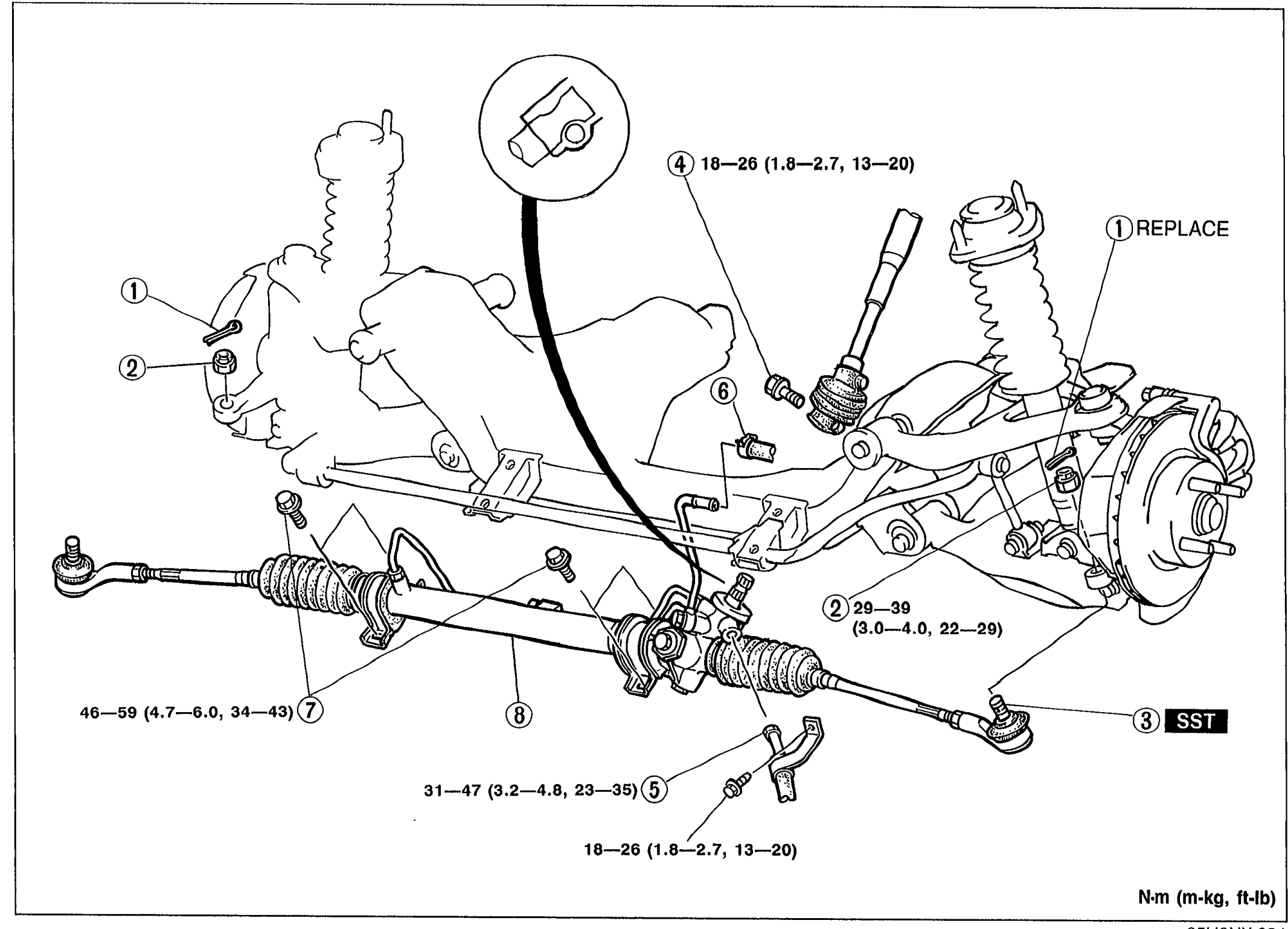 05U0NX-034
 - 5Install in the reverse order of removal, referring to Installation Note.
- 6Tighten all necessary bolts and nuts to the specified torque.
- 7After installation: (1) Check for fluid leakage. (Refer to page N-16.) (2) Bleed air from the system. (Refer to page N-15.)
Parts DiagramFig. fig1
| Specification | Value |
|---|---|
| Tie-rod end nut torque (callout 2) | 29 - 39N·m |
| Bolt torque (callout 4) | 18 - 26N·m |
| Mounting bracket bolt torque (callout 7) | 46 - 59N·m |
| Steering gear torque (callout 8) | 31 - 47N·m |
| Pressure pipe torque (callout 5) | 18 - 26N·m |
Tie-rod end nut torque (callout 2)
29 - 39N·m
Bolt torque (callout 4)
18 - 26N·m
Mounting bracket bolt torque (callout 7)
46 - 59N·m
Steering gear torque (callout 8)
31 - 47N·m
Pressure pipe torque (callout 5)
18 - 26N·m