
CAUTION (continued)
GI-13prose procedureHandling of Air Bag Module (continued)
- 3When placing a live air bag module on any surface, always face the trim cover upward. This will reduce the motion of the module if it is accidentally deployed.
- 4When handling a deployed air bag module, wear gloves and safety glasses because the deployed air bag module may display deposits of sodium hydroxide, a product of the gas generant combustion.
- 5An air bag module must disposed of only by the proper procedure recommended for the specific situation. (Refer to page T-160.)
Crash Sensor Installation
The angle and direction of the sensor is very important for its proper operation. If a vehicle has been involved in a crash where the its front sheet metal has been damaged, inspect the body structure at the sensor mounting area for deformation. If damaged, restore it to its original shape. When installing a crash sensor, be sure to tighten the mounting bolts to the specified torque to ensure proper grounding. The ground circuit is made directly through the sensor's mounting plate.
Adjustment of Clock Spring Connector
When the steering wheel is removed or the clock spring connector is replaced, the clockspring connector must be properly aligned.
Align the clock spring connector as follows:
- 1Set the front wheels straight ahead.
- 2Turn the clock spring connector clockwise until it stops. Do not force it.
- 3Return it 2.5 turns.
- 4Turn it (counterclockwise) the mark on the clock spring connector to the outer housing.
- 5Carefully install the steering wheel after positioning the clockspring connector.
BATTERY
- 1The battery is installed in the right rear of the trunk.
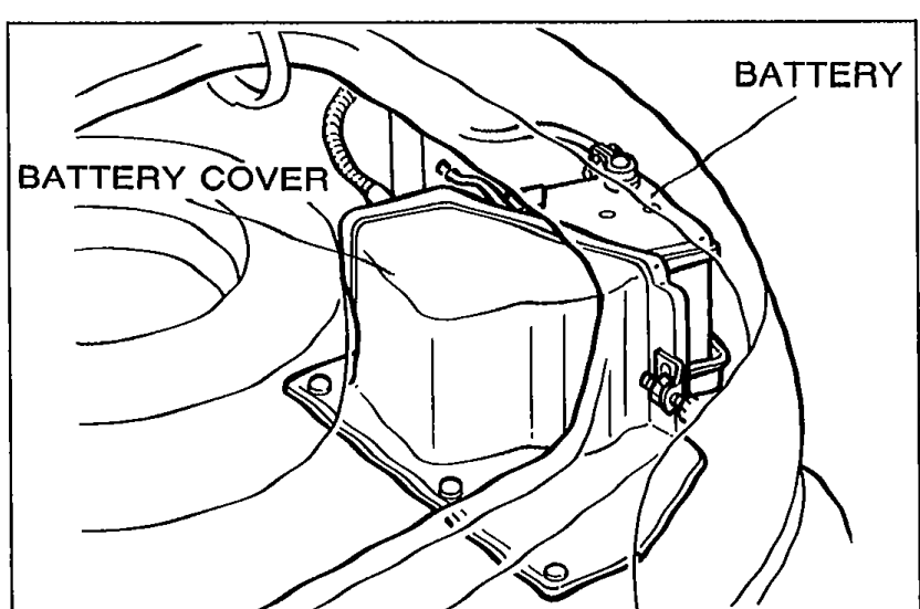 05UGIX-015
 - 2The battery installed in the MX-5 Miata is unique. When replacement battery is installed, install it with a Mazda genuine battery replacement kit or equivalent. (Refer to page G-10 for replacement.)
POWER CONNECTOR IN ENGINE COMPARTMENT
- 1When using externally powered test equipment, connect it to the special power connector (Blue: 1-pin) for battery voltage.
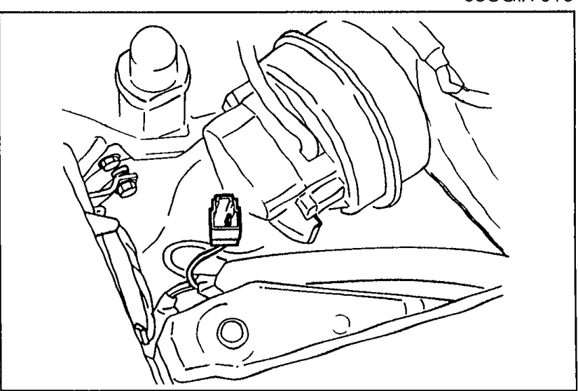 05UGIX-016
 - 2Do not ground the power connector terminal; the Wiper 20A fuse will be burned.
AUDIO ANTI-THEFT SYSTEM
An audio with an anti-theft function is optionally available. Before removing the negative battery cable or disconnecting the audio power source, obtain the code number and deactivate the audio anti-theft system. (Refer to page T-113.)