
CLUTCH PEDAL — Removal / Inspection / Installation
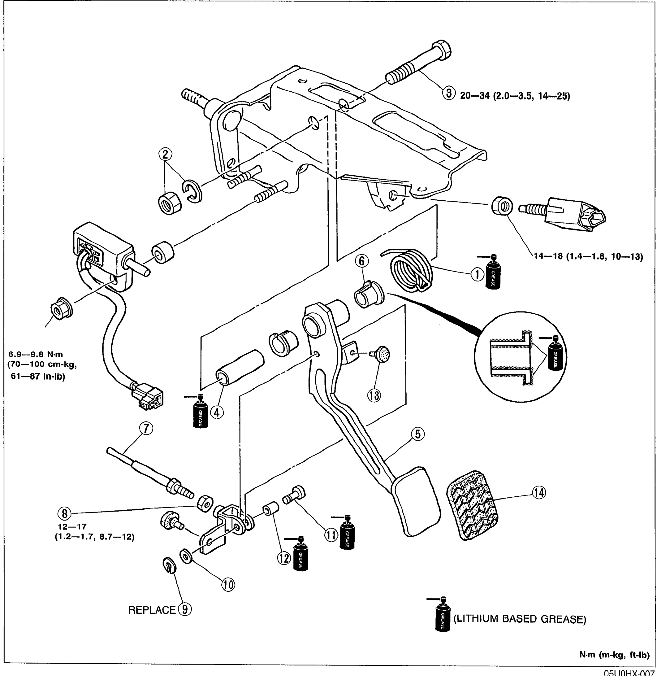
H-6parts diagramRemoval / Inspection / Installation
- 1Remove in the order shown in the figure, referring to Removal Note.
 05U0HX-007
 - 2Inspect all parts and repair or replace as necessary.Apply lithium based grease to the bushings and pin when installing.
- 3Install in the reverse order of removal, referring to Installation Note.
Parts DiagramFig. fig1
| Specification | Value |
|---|---|
| Tightening torque — clutch master cylinder mounting bolt (3) | 20-34N·m |
| Tightening torque — switch | 14-18N·m |
| Tightening torque — push rod nut (8) | 12-17N·m |
| Tightening torque — pedal shaft nut (2) | 6.9-9.8N·m |
| Tightening torque — pedal shaft nut (2) | 61—87in-lb |
Tightening torque — clutch master cylinder mounting bolt (3)
20-34N·m
Tightening torque — switch
14-18N·m
Tightening torque — push rod nut (8)
12-17N·m
Tightening torque — pedal shaft nut (2)
6.9-9.8N·m
Tightening torque — pedal shaft nut (2)
61—87in-lb