
STARTING SYSTEM — Disassembly / Assembly
G-26parts diagramDisassembly / Assembly
- 1Disassemble in the order shown in the figure.
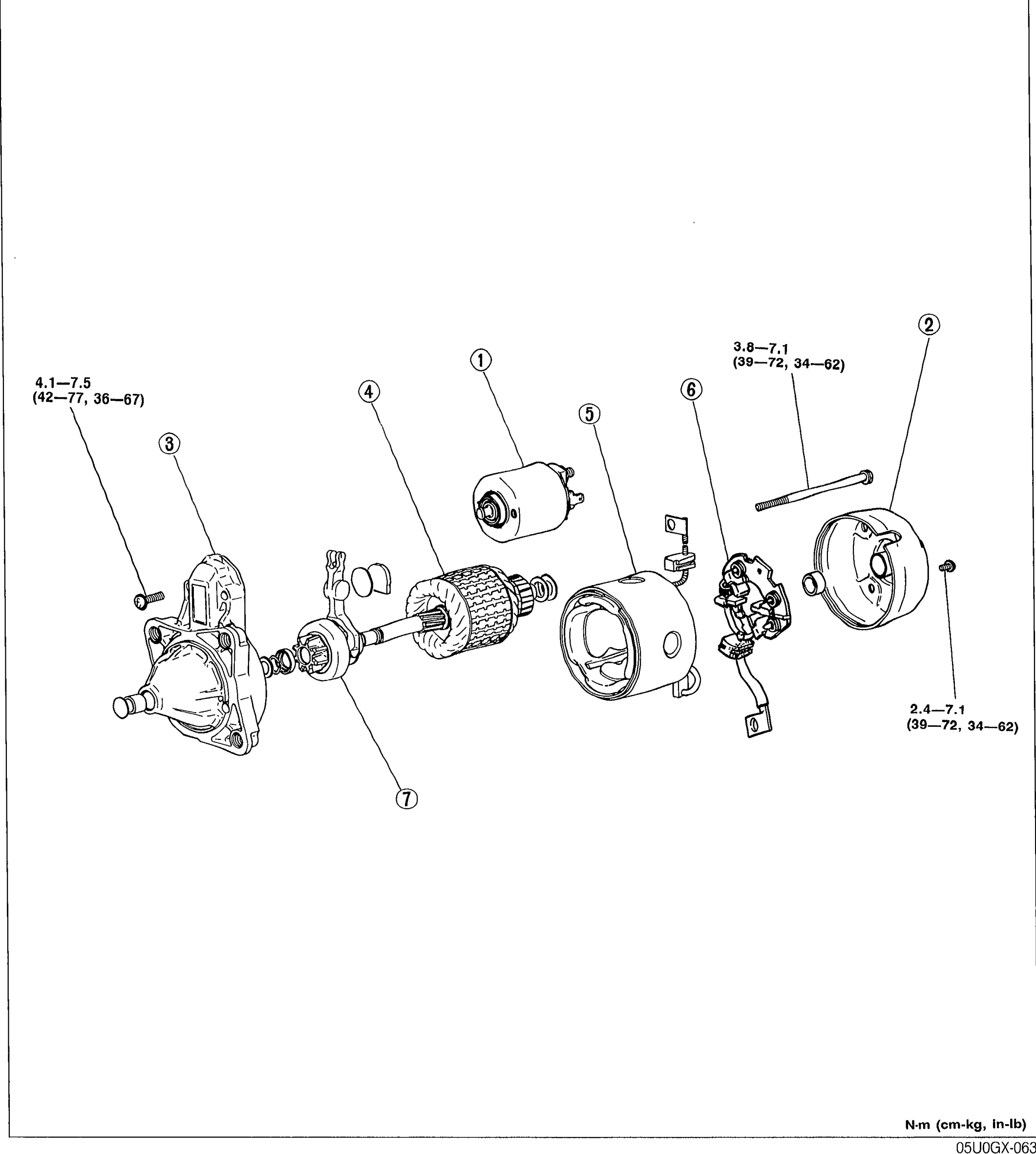 05U0GX-063
 - 2Inspect and repair or replace parts as necessary.
- 3Assemble in the reverse order of disassembly.
Parts DiagramFig. fig1
| Specification | Value |
|---|---|
| Tightening torque — front-cover screws | 4.1-7.5N·m |
| Tightening torque — front-cover screws | 36—67in-lb |
| Tightening torque — rear-housing through-bolts | 3.8-7.1N·m |
| Tightening torque — rear-housing through-bolts | 34—62in-lb |
| Tightening torque — magnetic-switch fastener | 2.4-7.1N·m |
| Tightening torque — magnetic-switch fastener | 34—62in-lb |
Tightening torque — front-cover screws
4.1-7.5N·m
Tightening torque — front-cover screws
36—67in-lb
Tightening torque — rear-housing through-bolts
3.8-7.1N·m
Tightening torque — rear-housing through-bolts
34—62in-lb
Tightening torque — magnetic-switch fastener
2.4-7.1N·m
Tightening torque — magnetic-switch fastener
34—62in-lb