
STARTING SYSTEM - Yoke assembly / Magnetic Switch / Brush and Brush Holder
G-28prose procedureYoke assembly
Yoke assembly inspection
- 1Wiring damage of field coil: (1) Check for continuity between the connector and the brushes with an ohmmeter. (2) Replace the yoke assembly if there is no continuity.
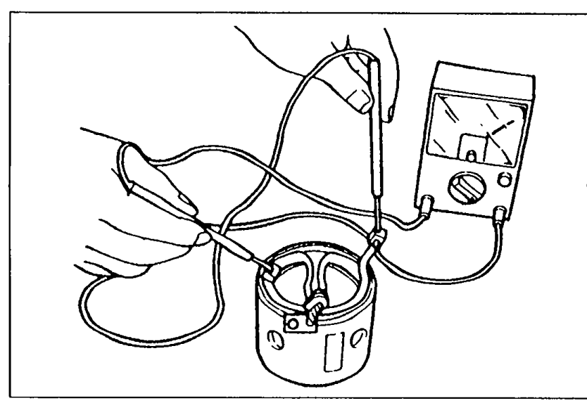 05U0GX-069
 - 2Ground of field coil: (1) Check for no continuity between the connector and the yoke with an ohmmeter. (2) Repair or replace the yoke assembly if there is continuity.
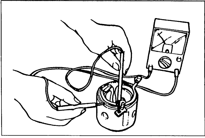 05U0GX-070
 - 3Installation of field coil: Replace the yoke assembly if the field coil is loose.
Magnetic Switch
Magnetic Switch inspection
- 1Wiring damage (S terminal — M terminal): Check for continuity between terminal S and terminal M with an ohmmeter. Replace the magnetic switch if there is no continuity.
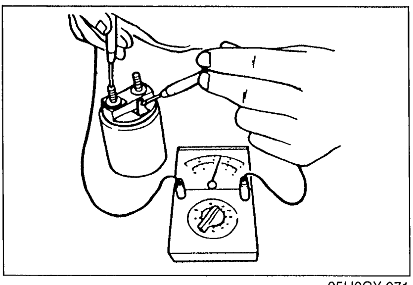 05U0GX-071
 - 2Wiring damage (S terminal — body): Check for continuity between terminal S and the body with an ohmmeter. Replace the magnetic switch if there is no continuity.
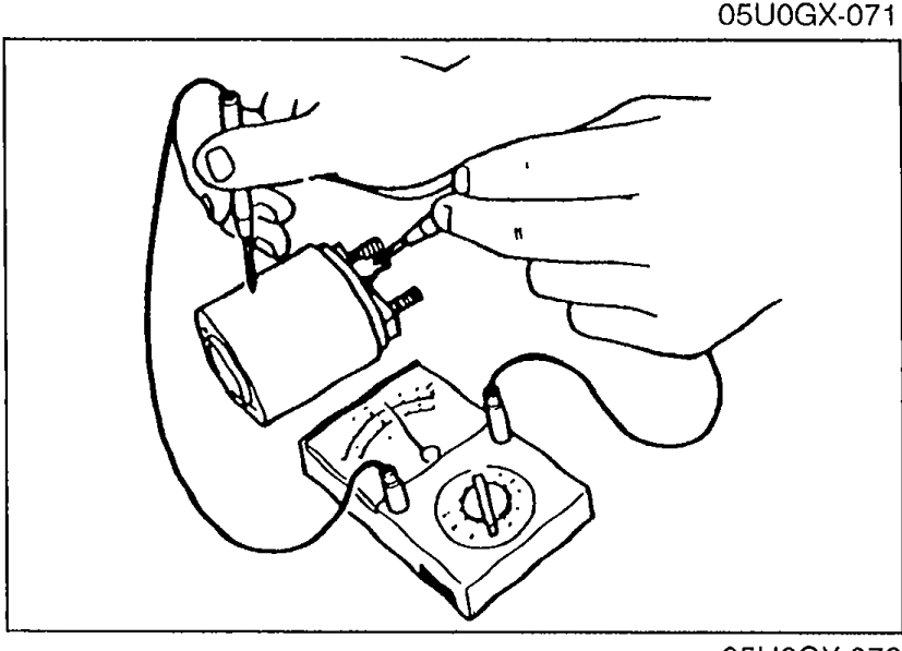 05U0GX-072
Brush and Brush Holder
Insulation of brush holder
Check for no continuity between each insulated brush and the plate with an ohmmeter. Replace the brush holder if there is continuity.