
CHARGING SYSTEM - ALTERNATOR
G-12prose procedureALTERNATOR
CAUTION
Obtain the code number and deactivate the audio anti-theft system before disconnecting the battery. (Refer to page T-113.)
Be sure the battery connections are not reversed because this will damage the rectifier.
Do not use high-voltage testers such as a megger because they will damage the rectifier.
Remember that battery voltage is always applied to the alternator B terminal.
Do not ground the L terminal while the engine is running.
Do not start the engine while the connector is disconnected from the L and S terminals.
SELF-DIAGNOSIS SYSTEM
The alternator has a self-diagnostic function to warn of problems in the charging system.
If any of the following problems arise, the alternator warning lamp illuminates.
1. S circuit open.
2. No voltage output.
3. Field circuit open.
4. B circuit open.
5. Voltage output too high.
Removal / Installation
Alternator Removal / Installation
- 1Disconnect the negative battery cable.
- 2Disconnect the P/S pressure switch connector.
- 3Disconnect the water thermoswitch connector.
- 4Disconnect the ISC valve connector.
- 5Remove the air pipe.
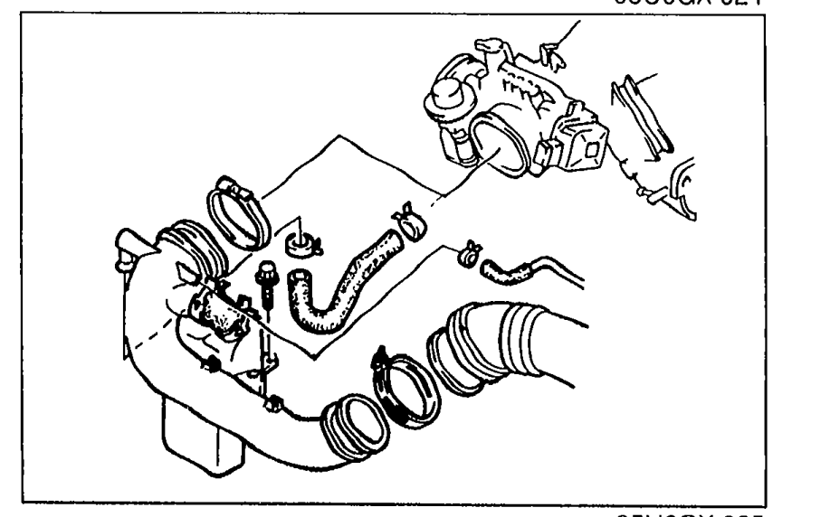 05U0GX-025
 - 6Disconnect the wire and connector from the alternator.
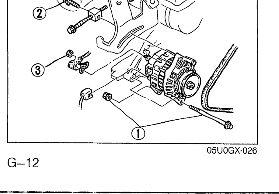 05U0GX-026
 - 7Remove the alternator bolts and nut.
- 8Remove the alternator.
- 10Install in the reverse order of removal.
| Specification | Value |
|---|---|
| Tightening torque — Bolt, Nut (1) | 37 - 52N·m |
| Tightening torque — Bolt (2) | 19 - 25N·m |
| Tightening torque — Nut (3) | 9.8 - 15N·m |
Tightening torque — Bolt, Nut (1)
37 - 52N·m
Tightening torque — Bolt (2)
19 - 25N·m
Tightening torque — Nut (3)
9.8 - 15N·m