
DRIVESHAFT
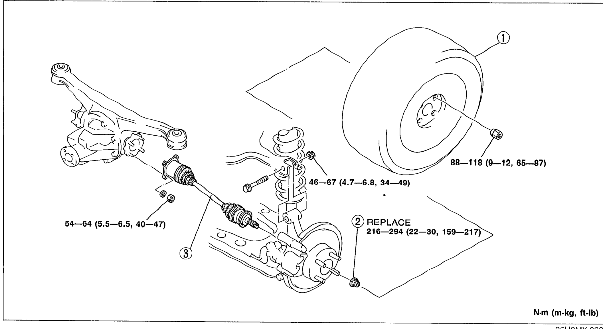
M-16parts diagramDOUBLE OFFSET JOINT
Inspection / Removal / Installation
- 1Inspect the driveshaft, referring to Inspection.
- 2Remove in the order shown in the figure, referring to Removal Note.
 05U0MX-033
 - 3Install in the reverse order of removal, referring to Installation Note.
- 4After installation, adjust the rear wheel alignment. (Refer to Section R.)
Parts DiagramFig. fig1
| Specification | Value |
|---|---|
| Rear wheel | 88 - 118N·m |
| Intermediate fastener | 46 - 67N·m |
| Inner driveshaft | 54 - 64N·m |
| Locknut | 216 - 294N·m |
Rear wheel
88 - 118N·m
Intermediate fastener
46 - 67N·m
Inner driveshaft
54 - 64N·m
Locknut
216 - 294N·m
Inspection
Driveshaft
Driveshaft inspection
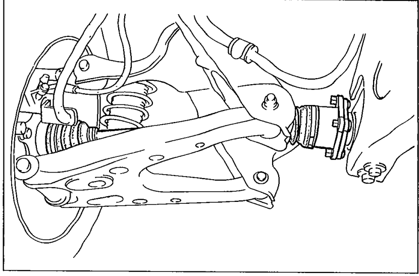
- 1Check the dust boot on the driveshaft for cracks, damage, leaking grease, and a loose boot band.
 05U0MX-034
 - 2Check the driveshaft for bending, cracks, and wear of joints or splines.
- 3Repair or replace the driveshaft if necessary.
Removal note
Driveshaft
Before removing the driveshaft, mark the driveshaft and output shaft for proper installation.