
FRONT AXLE
M-5parts diagramPREPARATION
SST
Special service tools
49 0118 850C
NamePuller, ball joint
UsageFor disconnection of tie-rod end and upper arm ball joint
49 0727 575
NamePuller, ball joint
UsageFor disconnection of lower arm ball joint
WHEEL HUB, STEERING KNUCKLE
Inspection / Removal / Installation
Wheel hub, steering knuckle — Inspection / Removal / Installation
- 1Inspect wheel bearing play, referring to Inspection.
- 2Remove in the order shown in the figure, referring to Removal Note.
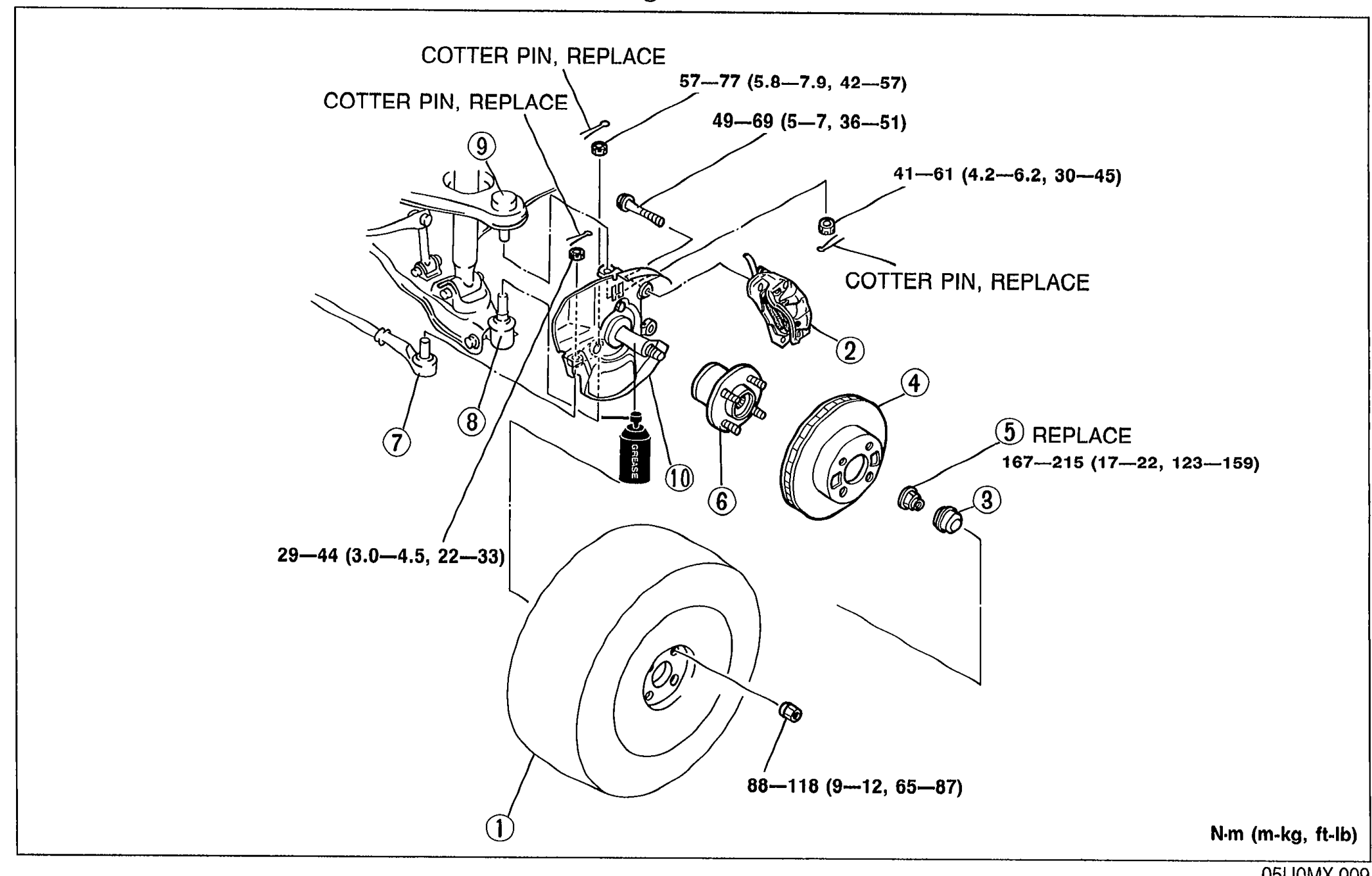 05U0MX-009
 - 3Inspect all parts and repair or replace as necessary.
- 4Install in the reverse order of removal, referring to Installation Note.
Parts DiagramFig. fig2
Tightening torques (N·m (m-kg, ft-lb))
Tie-rod end (callout 7)
N·m29—44
m-kg3.0—4.5
ft-lb22—33
Upper arm ball joint (callout near 9)
N·m41—61
m-kg4.2—6.2
ft-lb30—45
Brake caliper assembly
N·m49—69
m-kg5—7
ft-lb36—51
Caliper bracket
N·m57—77
m-kg5.8—7.9
ft-lb42—57
Front wheel hub locknut (callout 5)
N·m167—215
m-kg17—22
ft-lb123—159
Lower arm ball joint (callout near 8)
N·m88—118
m-kg9—12
ft-lb65—87