
DIFFERENTIAL
M-38prose procedurePinion height measurement
- 7Place the SST on the surface plate and set the dial indicator to "Zero".
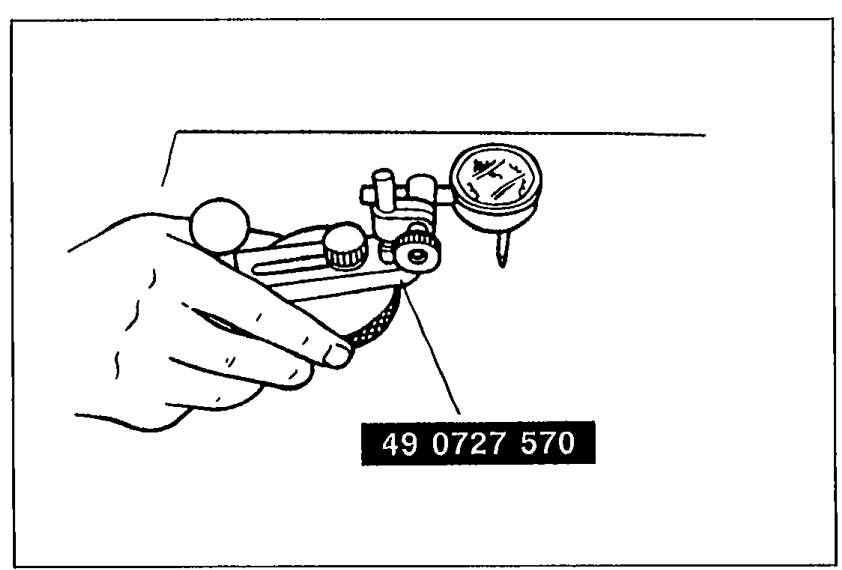 69G09X-172
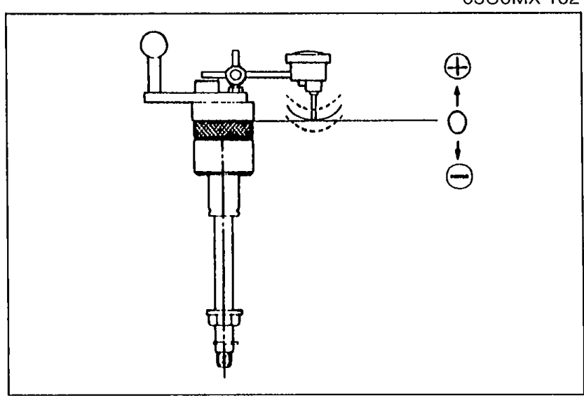
 - 8Place the SST atop the drive pinion model. Set the gauge body atop the gauge block.
 05U0MX-102
 - 9Place the feeler of the dial indicator so that it contacts where the bearing inner race (side bearing) is installed in the carrier. Measure the lowest position on the left and right sides of the carrier.
- 10Add the two (left and right) values obtained in Step 9 and divide the total by 2.
 05U0MX-103
| Specification | Value |
|---|---|
| Specificationaverage of left/right measurements | 0 (0)mm (in) |
Specificationaverage of left/right measurements
0 (0)mm (in)
Spacer selection
- 11If not within specification, adjust the pinion height by selection of a spacer.Spacers are available in increments of 0.03mm. Select the spacer thickness that is closest to that necessary.
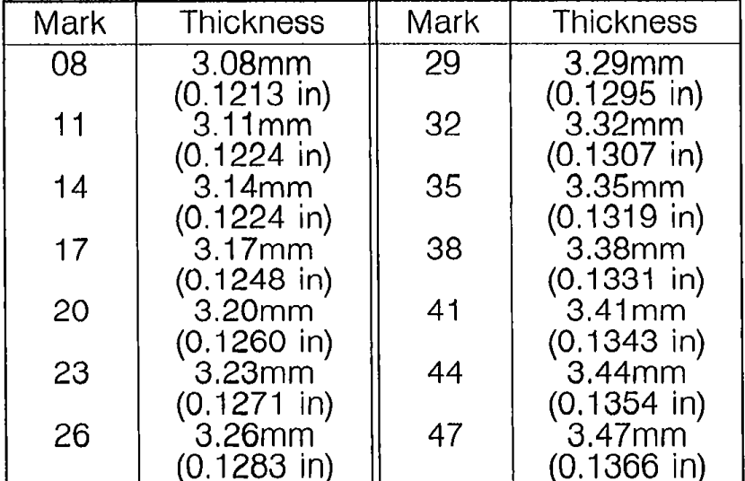 05U0MX-104
Spacer mark vs. thickness
08
Thickness3.08 mm (0.1213 in)
11
Thickness3.11 mm (0.1224 in)
14
Thickness3.14 mm (0.1224 in)
17
Thickness3.17 mm (0.1248 in)
20
Thickness3.20 mm (0.1260 in)
23
Thickness3.23 mm (0.1271 in)
26
Thickness3.26 mm (0.1283 in)
29
Thickness3.29 mm (0.1295 in)
32
Thickness3.32 mm (0.1307 in)
35
Thickness3.35 mm (0.1319 in)
38
Thickness3.38 mm (0.1331 in)
41
Thickness3.41 mm (0.1343 in)
44
Thickness3.44 mm (0.1354 in)
47
Thickness3.47 mm (0.1366 in)
Adjustment of drive pinion preload
- 1Install the spacer.Press on until the force required suddenly increases.Install the spacer selected for the pinion height adjustment, being careful that the installation direction is correct.
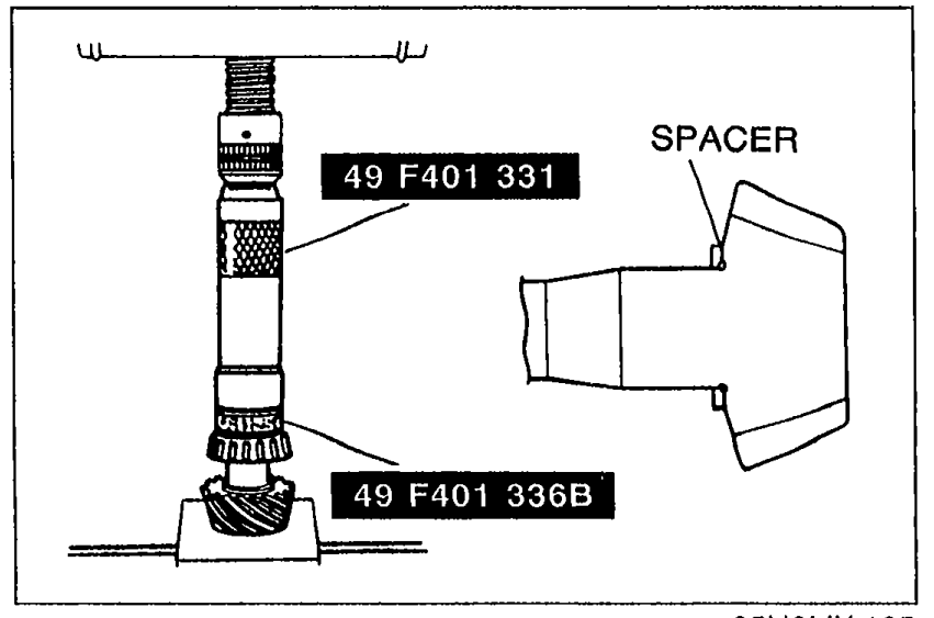 05U0MX-105
 - 2Press the bearing inner race (rear bearing) on with the SST.