
FRONT SUSPENSION (DOUBLE-WISHBONE) - UPPER ARM
R-17prose procedureUPPER ARM
Removal / Inspection / Installation
Upper Arm - Removal / Inspection / Installation
- 1Jack up the front of the vehicle and support it with safety stands.
- 2Remove the undercover.
- 3Remove in the order shown in the figure, referring to Removal Note.
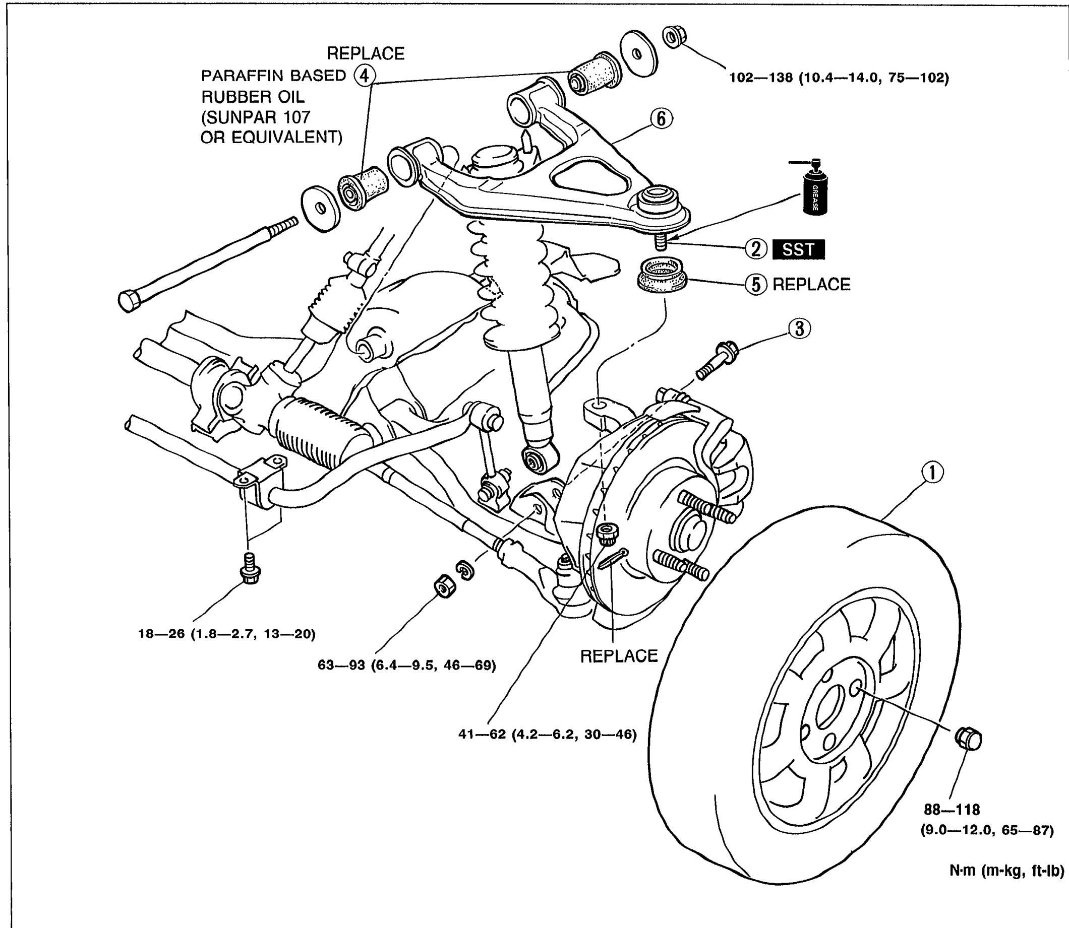 05U0RX-038
 - 4Inspect all parts and repair or replace as necessary.
- 5Install in the reverse order of removal, referring to Installation Note.
- 6Tighten all nuts and bolts to the specified torques, referring to the figure.Loosely tighten the upper arm and shock absorber bolts. Lower the vehicle and tighten all nuts and bolts to the specified torques with the vehicle unladed.
- 7Adjust the front wheel alignment. (Refer to page R-6.)
| Specification | Value |
|---|---|
| Wheel nut (1)9.0-12.0 m-kg, 65-87 ft-lb | ≈88 - 118N·m |
| Upper arm ball joint nut (2)4.2-6.2 m-kg, 30-46 ft-lb; REPLACE | ≈41 - 61N·m |
| Shock absorber bolt (3)6.4-9.5 m-kg, 46-69 ft-lb | ≈63 - 93N·m |
| Upper arm bushing bolt (4)1.8-2.7 m-kg, 13-20 ft-lb | ≈18 - 26N·m |
| Upper arm mounting (6)10.4-14.0 m-kg, 75-102 ft-lb | ≈102 - 137N·m |
Wheel nut (1)9.0-12.0 m-kg, 65-87 ft-lb
88 - 118N·m
Upper arm ball joint nut (2)4.2-6.2 m-kg, 30-46 ft-lb; REPLACE
41 - 61N·m
Shock absorber bolt (3)6.4-9.5 m-kg, 46-69 ft-lb
63 - 93N·m
Upper arm bushing bolt (4)1.8-2.7 m-kg, 13-20 ft-lb
18 - 26N·m
Upper arm mounting (6)10.4-14.0 m-kg, 75-102 ft-lb
102 - 137N·m
Parts DiagramFig. fig1