
WHEEL ALIGNMENT
R-6prose procedurePre-Inspection
- 1Check the tire inflations, and adjust to the recommended pressure if necessary.
- 2Inspect the front wheel bearing paly and correct if necessary.
- 3Inspect the wheel and tire runouts.
- 4Inspect the ball joints and steering linkage for excessive looseness.
- 5The vehicle must be on level ground and carry no luggage or passengers.
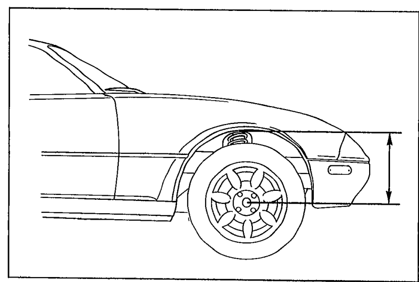
- 6Measure the height from the center of the wheel to the fender brim. The difference between left and right must not exceed 10mm (0.31 in), and the difference between front and rear must be 20mm ± 10mm (0.62 ± 0.31 in).
 05U0RX-007
CAUTION
The proper caster and camber angle vary depending on the vehicle height. Refer to the following and to page R-9 for the specifications.
Inspection and adjustment of wheel alignment must be done with the vehicle unladed*1.
FRONT WHEEL ALIGNMENT
Specifications (Unladed*1)
Front Wheel Alignment Specifications
Total toe-in
Sub-item
Unit / Rangemm (in)
Specifications3 ± 3 (0.12 ± 0.12)
Total toe-in
Sub-item
Unit / Rangedegree
Specifications0°18' ± 18'
Maximum steering angle
Sub-itemInner
Unit / Range
Specifications37°23' ± 2°
Maximum steering angle
Sub-itemOuter
Unit / Range
Specifications32°32' ± 2°
Kingpin angle
Sub-item
Unit / Range
Specifications11°20'
Camber angle
Sub-itemHeight from center of wheel to fender brim mm (in)
Unit / Range328—337 (12.9—13.3)
Specifications-0°20' ± 45'*2
Camber angle
Sub-itemHeight from center of wheel to fender brim mm (in)
Unit / Range338—347 (13.3—13.7)
Specifications0°03' ± 45'*2
Camber angle
Sub-itemHeight from center of wheel to fender brim mm (in)
Unit / Range348—357 (13.7—14.1)
Specifications0°24' ± 45'*2
Camber angle
Sub-itemHeight from center of wheel to fender brim mm (in)
Unit / Range358—367 (14.1—14.4)
Specifications0°44' ± 45'*2
Camber angle
Sub-itemHeight from center of wheel to fender brim mm (in)
Unit / Range368—377 (14.4—14.8)
Specifications1°02' ± 45'*2
Caster angle
Sub-itemHeight from center of wheel to fender brim mm (in)
Unit / Range328—337 (12.9—13.3)
Specifications5°16' ± 45'
Caster angle
Sub-itemHeight from center of wheel to fender brim mm (in)
Unit / Range338—347 (13.3—13.7)
Specifications5°02' ± 45'
Caster angle
Sub-itemHeight from center of wheel to fender brim mm (in)
Unit / Range348—357 (13.7—14.1)
Specifications4°49' ± 45'
Caster angle
Sub-itemHeight from center of wheel to fender brim mm (in)
Unit / Range358—367 (14.1—14.4)
Specifications4°35' ± 45'
Caster angle
Sub-itemHeight from center of wheel to fender brim mm (in)
Unit / Range368—377 (14.4—14.8)
Specifications4°21' ± 45'
NOTE
*1 Fuel tank full; radiator coolant and engine oil at specified levels; spare tire, jack, and tools in designated positions.
*2 Difference between left and right must not exceed 1°.
Adjustment
Maximum steering angle
Maximum steering angle adjustment
- 1Remove the steering gear boot clamp.
 05U0RX-010
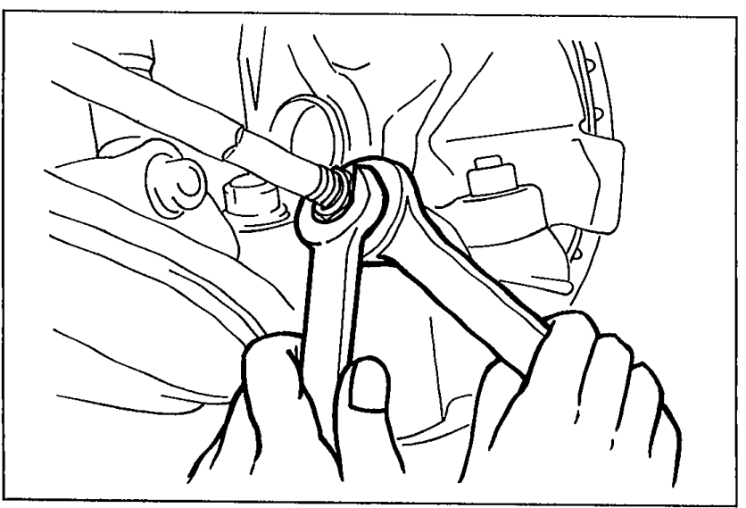
 - 2Loosen the tie-rod locknut.
- 3Turn the tie-rod to provide the correct maximum steering angle.
- 4After adjustment, tighten the locknut to the specified torque.
- 5Adjust the toe-in. (Refer to page R-8.)
- 6Verify that the boot is not twisted, and install the boot clamp.
| Specification | Value |
|---|---|
| Tightening torque (Tie-rod locknut) | 34 - 39N·m |
Tightening torque (Tie-rod locknut)
34 - 39N·m
05U0RX-009