Mazda MX-5 NA silhouetteMX-5 NA

TRANSMISSION — Mainshaft and Countershaft Parts (parts list + disassembly notes)

J-17parts diagram

M/T

Mainshaft and Countershaft Parts (parts list)

Parts DiagramFig. page-0348 fig1
Parts diagram
#Part NameNotes
1Snap ring
2Washer
3Retaining ring
4C-washer
5Mainshaft rear bearingDisassembly Note page J-17; Inspection page J-24
6Retaining ring
7C-washer
8Thrust lock washer
9Steel ball
10Locknut (Countershaft)Disassembly Note page J-17
11Countershaft rear bearingDisassembly Note page J-18; Inspection page J-24
12Counter 5th gearInspection page J-23
13Spacer
145th gearInspection page J-23
15Synchronizer ring (5th)Inspection page J-24
16Locknut (Mainshaft)Disassembly Note page J-18
17Clutch hub assembly (5th/Reverse)Inspection page J-23
18Synchronizer ring (Reverse)Inspection page J-24
19Reverse gearInspection page J-23
20Needle bearingInspection page J-24
21Inner race
22Washer
23Counter reverse gearInspection page J-23
24Main drive gear bearingDisassembly Note page J-18; Inspection page J-24
25Snap ring
26Countershaft front bearingDisassembly Note page J-18; Inspection page J-24
27Bearing housing assemblyDisassembly Note page J-18; Disassembly page J-20
28Mainshaft gear assembly
29Main drive gearInspection page J-23
30Synchronizer ring (4th)Inspection page J-24
31Needle bearingInspection page J-24
32Washer
33CountershaftInspection page J-24
34Synchronizer key spring
35Clutch hub sleeve
36Synchronizer key
37Clutch hub

Disassembly note — Mainshaft rear bearing

Remove the mainshaft rear bearing with the SST.

Disassembly note — Locknut (Countershaft)

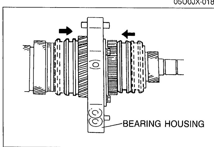
Locknut disassembly

  1. 1
    Shift the clutch hub sleeves to first gear and reverse gear to put the gears in the double-engaged condition.
    Do not reuse the locknut.
    Do not damage the countershaft.
    Countershaft assembly with arrows showing the clutch hub sleeves shifted to first gear and reverse gear placing the gears in double-engaged condition; bearing housing labeled.
    97U0J1-020
  2. 2
    Use a suitable tool to uncrimp the tabs of the locknut.
  3. 3
    Connect the SST to the mainshaft and tighten it securely in a vise.
    Use pads in the vise to prevent damaging the SST.
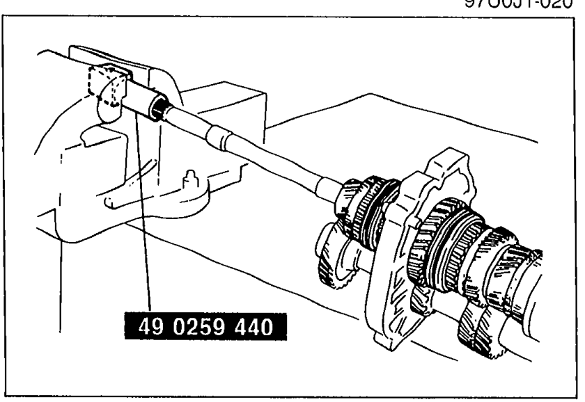
    Mainshaft clamped in vise using SST 49 0259 440. Hands operate the SST to hold the mainshaft for locknut removal.
    97U0J1-021
  4. 4
    Remove the locknut.

Search Manual

Search pages, specs, and procedures