
BRAKE SYSTEM
P-10parts diagramMASTER CYLINDER
Removal / Installation
- 1Remove in the order shown in the figure, referring to Removal Note.
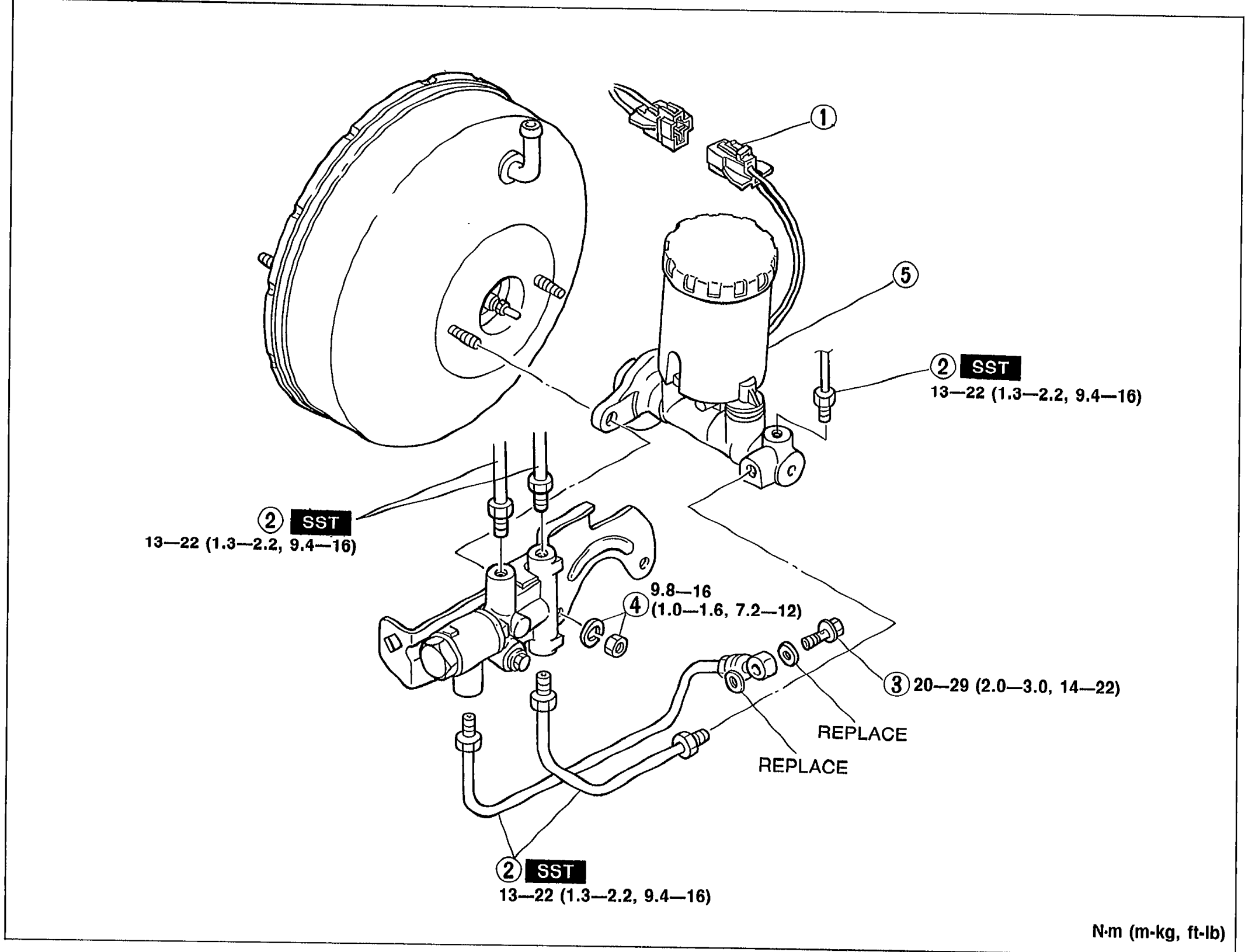 05U0PX-016
 - 2Install in the reverse order of removal, referring to Installation Note.
- 3After installation, add brake fluid, bleed air, and check for fluid leakage.
CAUTION
Brake fluid will damage painted surfaces. If it does get on a painted surface, wipe it off immediately.
| Specification | Value |
|---|---|
| Brake pipe torque (callout 2, SST) | ≈127 - 216N·m |
| Washers/banjo torque (callout 3, REPLACE) | ≈196 - 284N·m |
| Nut and washer torque (callout 4) | ≈96 - 157N·m |
Brake pipe torque (callout 2, SST)
127 - 216N·m
Washers/banjo torque (callout 3, REPLACE)
196 - 284N·m
Nut and washer torque (callout 4)
96 - 157N·m
Parts DiagramFig. fig1
Removal note
Brake pipe
Disconnect/connect the brake pipe from/to the master cylinder with the SST.