
BRAKE SYSTEM
P-9parts diagramRemoval / Inspection / Installation
- 1Remove in the order shown in the figure.
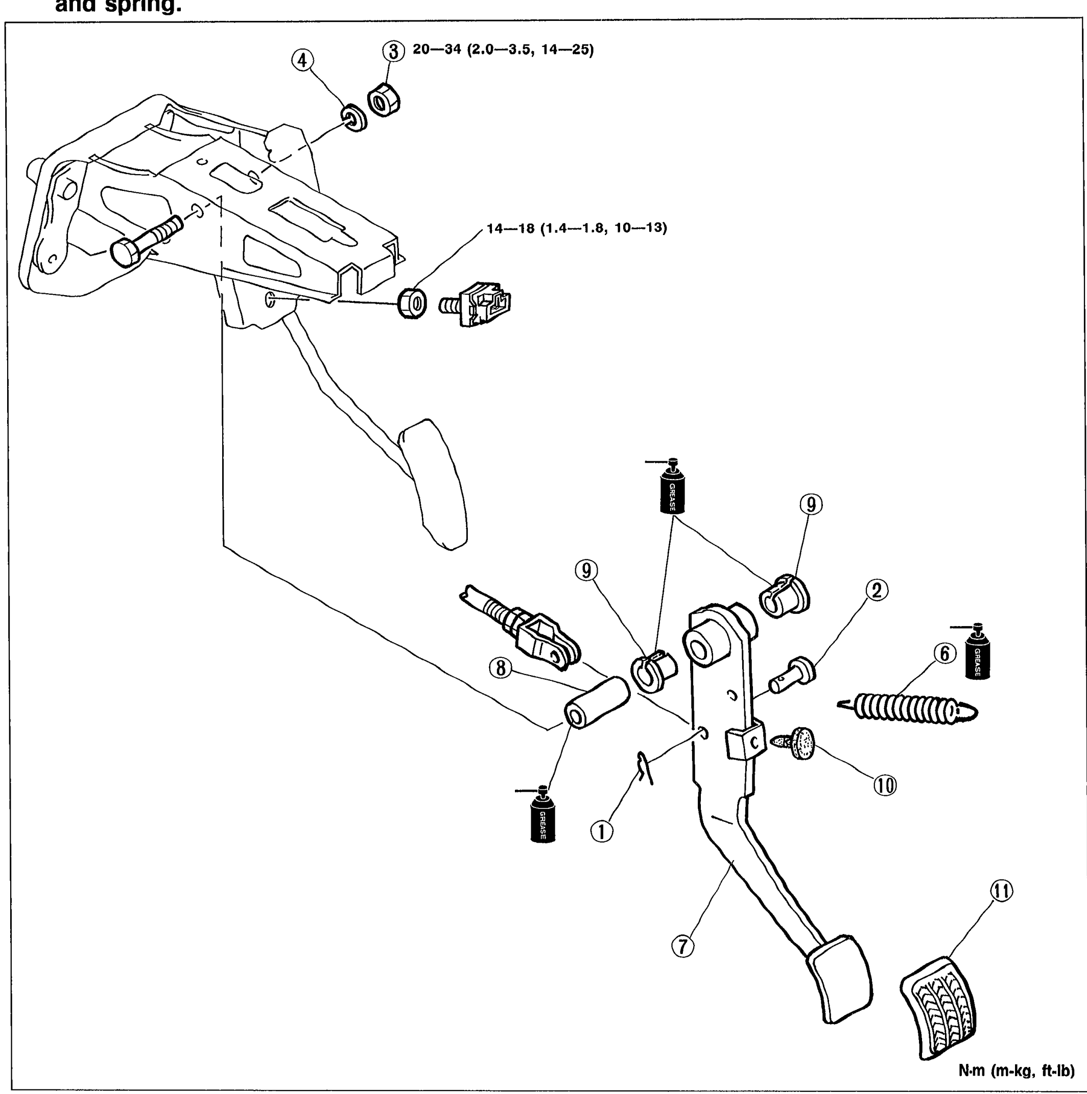 05U0PX-015
 - 2Inspect all parts and repair or replace as necessary.
- 3Install in the reverse order of removal.
- 4After installation, check and adjust the pedal height and free play if necessary.
CAUTION
Apply grease to the inner surface of the bushing and to the contact surfaces of the clevis pin and spring.
| Specification | Value |
|---|---|
| Upper bracket bolts | ≈196 - 333N·m |
| Stoplight switch / lower fastener | ≈137 - 177N·m |
Upper bracket bolts
196 - 333N·m
Stoplight switch / lower fastener
137 - 177N·m
Parts DiagramFig. fig1