Mazda MX-5 NA silhouetteMX-5 NA

BRAKE SYSTEM — Installation / Removal / Installation (Caliper)

P-19parts diagram

Installation

Disc pad

Installation — Disc pad

  1. 1
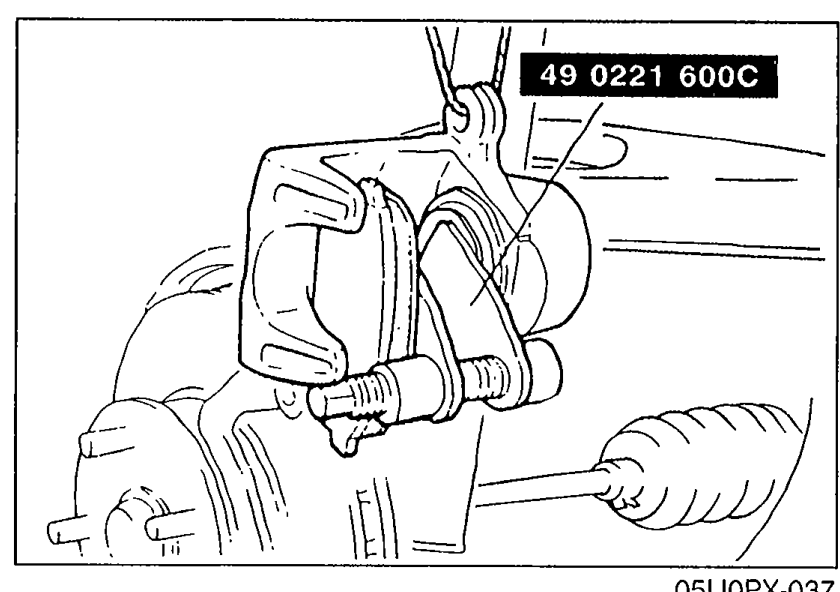
    Push the piston inward with the SST.
    Illustration of the front brake caliper with SST 49 0221 600C (piston pusher / C-clamp style) installed across the caliper to push the piston inward in preparation for new pad installation.
    05U0PX-037
  2. 2
    Install the new pads in the mounting support.

Removal / Installation

Caliper

Removal / Installation — Caliper

  1. 1
    Jack up the front of the vehicle and support it with safety stands.
  2. 2
    Remove the wheels; then remove components in the order shown in the figure.
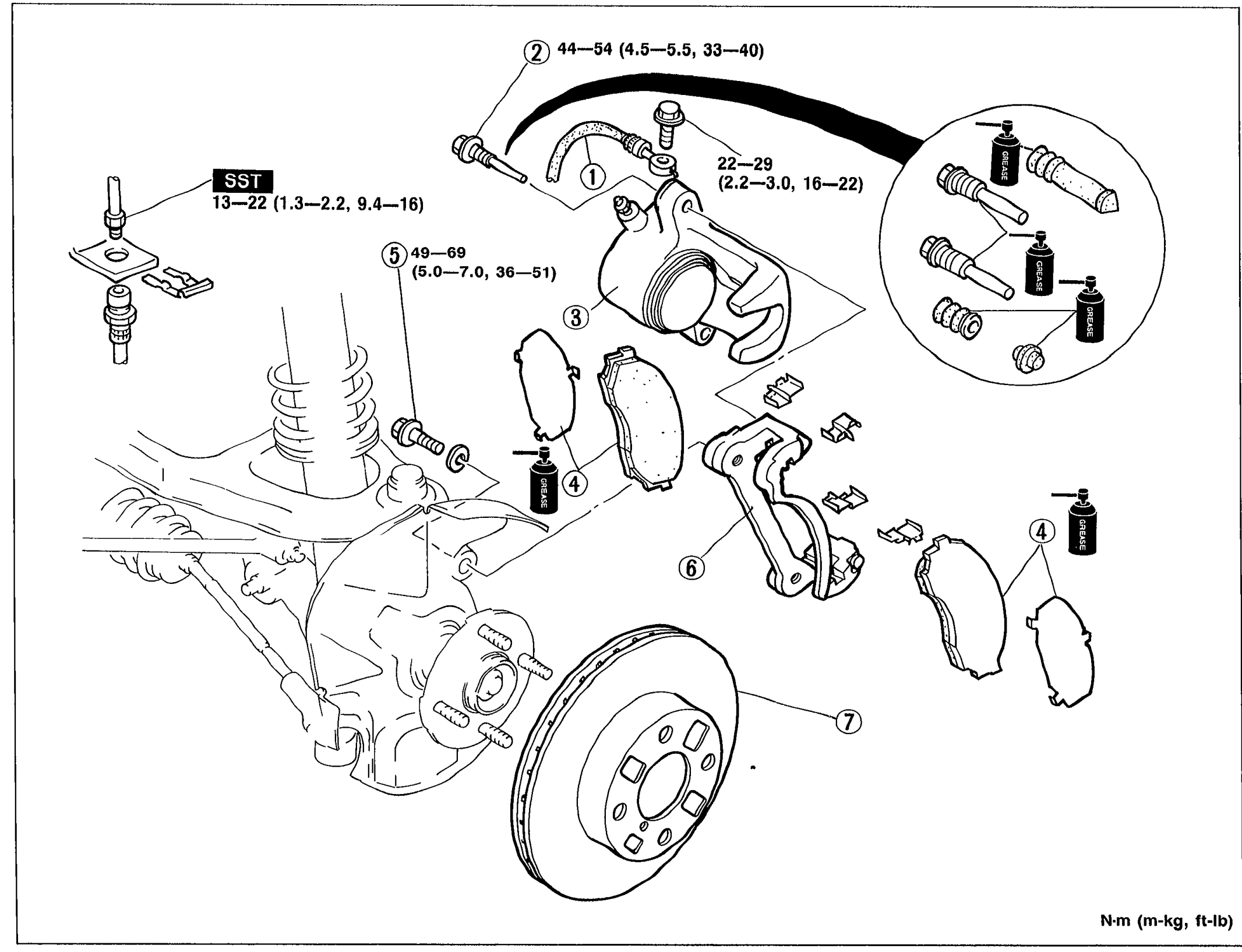
    Exploded view of front brake caliper removal/installation. Shows the strut and rotor on the left, then the caliper assembly with brake hose (1), lock bolts (2) with 44—54 N·m torque, brake caliper assembly (3) with 49—69 N·m torque, disc pad assembly (4), bolt (5) with 22—29 N·m torque, mounting support (6), and disc plate (7). SST marker is present at the brake-hose flare-nut fitting (13—22 N·m). Grease bottle icons appear next to slide pins and shims indicating apply grease.
    05U0PX-038
  3. 3
    Install in the reverse order of removal.
  4. 4
    Tighten all nuts and bolts to the specified torques, referring to the figure.
Parts DiagramFig. fig2
#Part NameNotes
1Brake hoseTightening torque: 13—22 N·m (1.3—2.2 m-kg, 9.4—16 ft-lb); SST used
2Lock boltTightening torque: 44—54 N·m (4.5—5.5 m-kg, 33—40 ft-lb)
3Brake caliper assemblyDisassembly / Assembly page P-21. Tightening torque: 49—69 N·m (5.0—7.0 m-kg, 36—51 ft-lb)
4Disc pad assemblyInspection page P-20
5BoltTightening torque: 22—29 N·m (2.2—3.0 m-kg, 16—22 ft-lb)
6Mounting support
7Disc plateInspection page P-20

Search Manual

Search pages, specs, and procedures