
BRAKE SYSTEM — PROPORTIONING BYPASS VALVE
P-16prose procedurePROPORTIONING BYPASS VALVE
Inspection
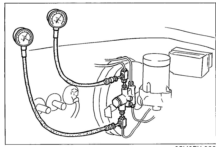
- 1Connect two pressure gauges [9,810 kPa (100 kg/cm², 1,422 psi)] to the pipes.
 05U0PX-030
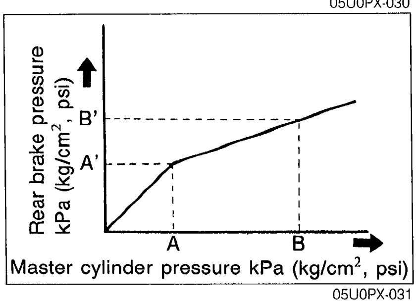
 - 2Measure the fluid pressure from the master cylinder and to the rear brake.
 05U0PX-031
Specification
Fluid pressure kPa (kg/cm², psi)
2,943 (30, 427)
A'2,943 ± 196 (30 ± 2, 427 ± 28)
B6,867 (70, 995)
B'4,120 ± 294 (42 ± 3, 597 ± 43)
CAUTION
• If not as specified, replace the valve assembly.
• After inspection:
Add brake fluid and bleed the air.
(Refer to page P-6.)
Check the brake lines for fluid leakage.
Replacement
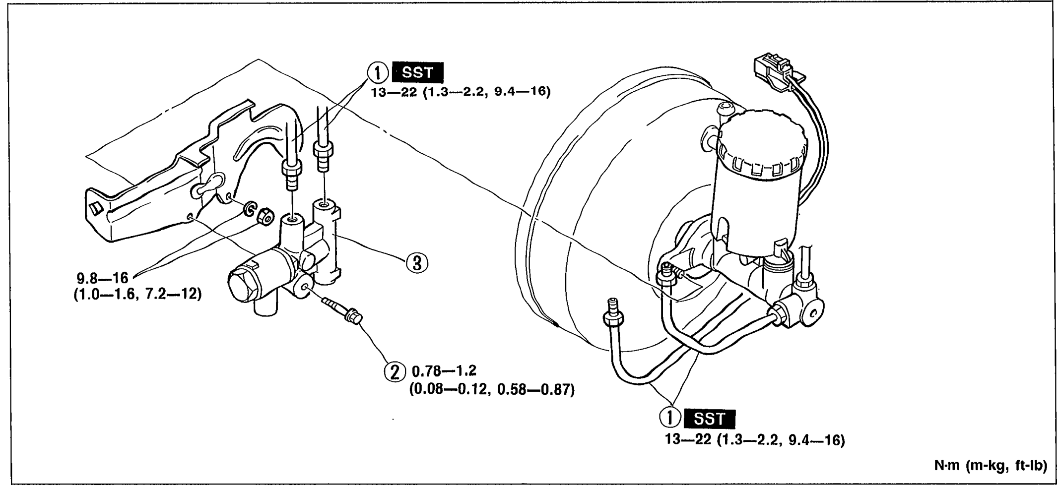
- 1Remove in the order shown in the figure.
 05U0PX-032
 - 2Install in the reverse order of removal.
- 3After installation: (1) Add brake fluid and bleed the air. (Refer to page P-6.) (2) Check the brake lines for fluid leakage.
CAUTION
• Brake fluid will damage painted surfaces. If it does get on a painted surface, wipe it off immediately.
Parts DiagramFig. fig3