
BRAKE SYSTEM
P-11prose procedureInstallation note
Push rod clearance
Measure the clearance between the push rod of the power brake unit and the piston of the master cylinder.
Push rod clearance
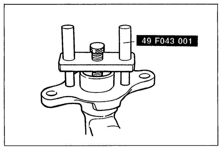
- 1Place the SST atop the master cylinder. Turn the adjustment bolt until it bottoms in the piston.
 05U0PX-017
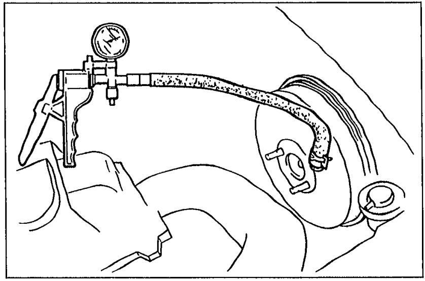
 - 2Apply 500 mmHg (19.7 inHg) vacuum to the power brake unit with a vacuum pump.
 9MU0PX-022
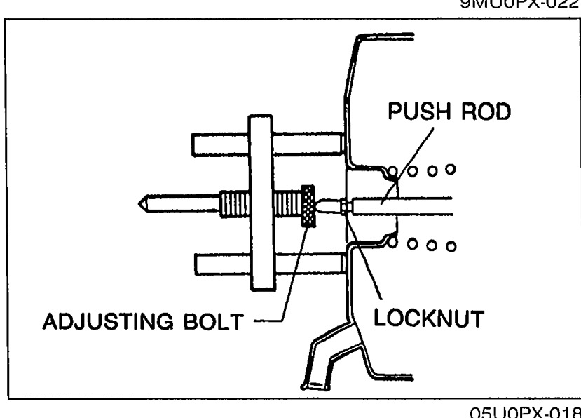
 - 3Invert the adjustment gauge used in Step 1, and place it on the power brake unit.
- 4Measure the clearance between the end of the adjustment bolt and the push rod of the power brake unit. If it is not 0mm (0 in), loosen the push rod locknut and turn the push rod to make the adjustment.
 05U0PX-018
Reference
By making the above adjustment, the clearance between the push rod and piston (after installation of the brake master cylinder and the power brake unit) will be as shown in the table below.
Push rod-to-piston clearance reference
When vacuum applied to unit is approx. 500 mmHg (19.7 inHg)
Clearance0.1—0.3mm (0.004—0.012 in)
Inspection
Fluid level sensor
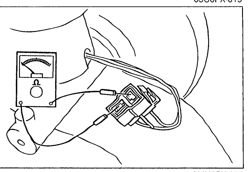
- 1Disconnect the sensor connector.
 9MU0PX-025
 - 2Connect an ohmmeter to the connector.
- 3Starting with the fluid level above the MIN mark on the reservoir, verify that there is no continuity.
- 4Remove the brake fluid and verify continuity when the level is below the MIN mark.
- 5Replace the sensor if necessary.