
BRAKE SYSTEM
P-12parts diagramDisassembly / Assembly / Inspection
- 1After removing the brake fluid, disassemble in the order shown in the figure, referring to Disassembly Note.
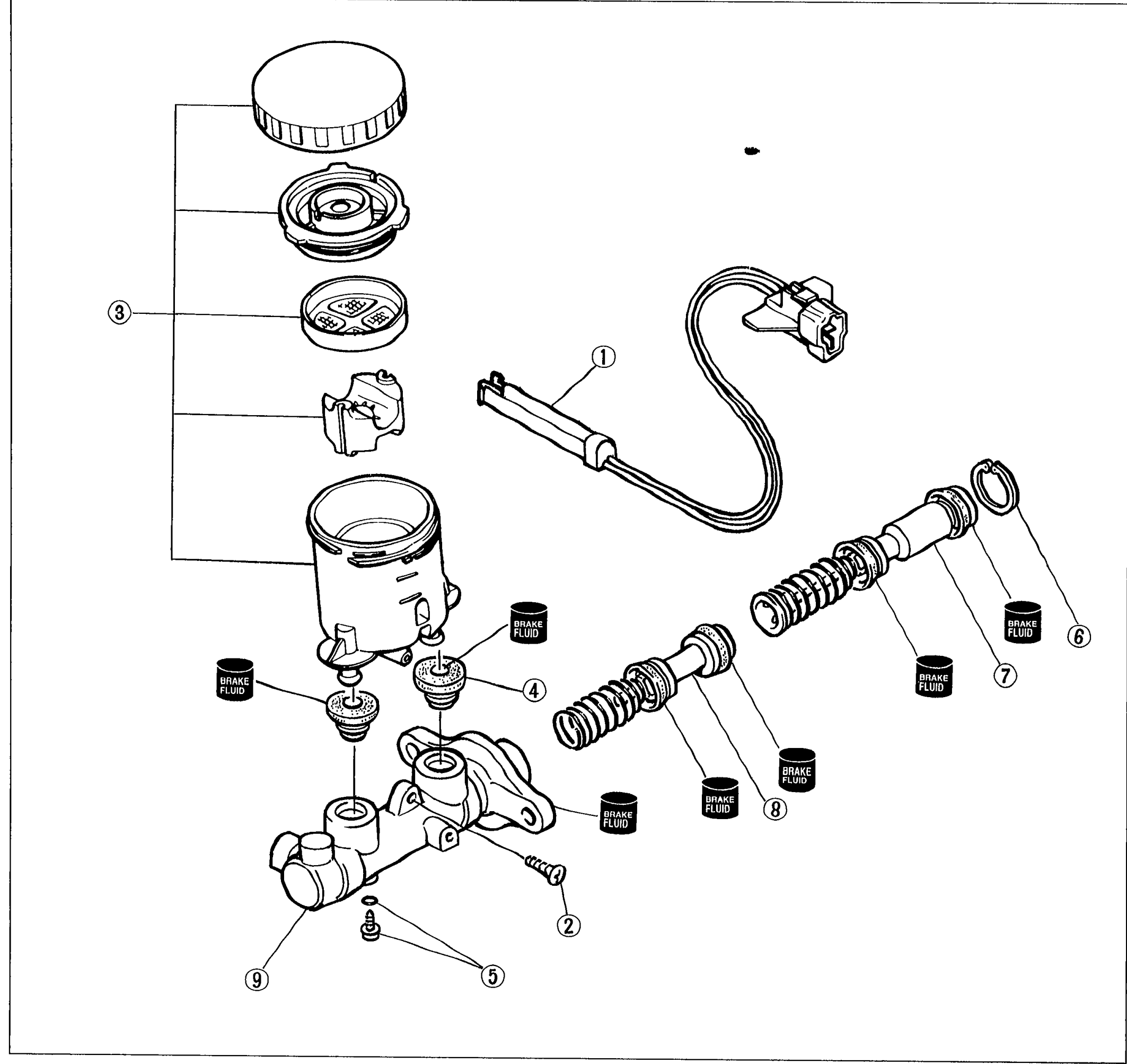 05U0PX-020
 - 2Inspect all parts and repair or replace as necessary.
- 3Assemble in the reverse order of removal, referring to Assembly Note.
CAUTION
Secure the master cylinder flange in a vise when necessary.
Replace the piston assembly if necessary.
Do not let foreign material enter the cylinder, and do not scratch the inside of the cylinder or the outer surface of the piston.
Parts DiagramFig. fig1