Mazda MX-5 NA silhouetteMX-5 NA

BRAKE SYSTEM

P-15parts diagram

Removal / Installation

  1. 1
    Remove in the order shown in the figure.
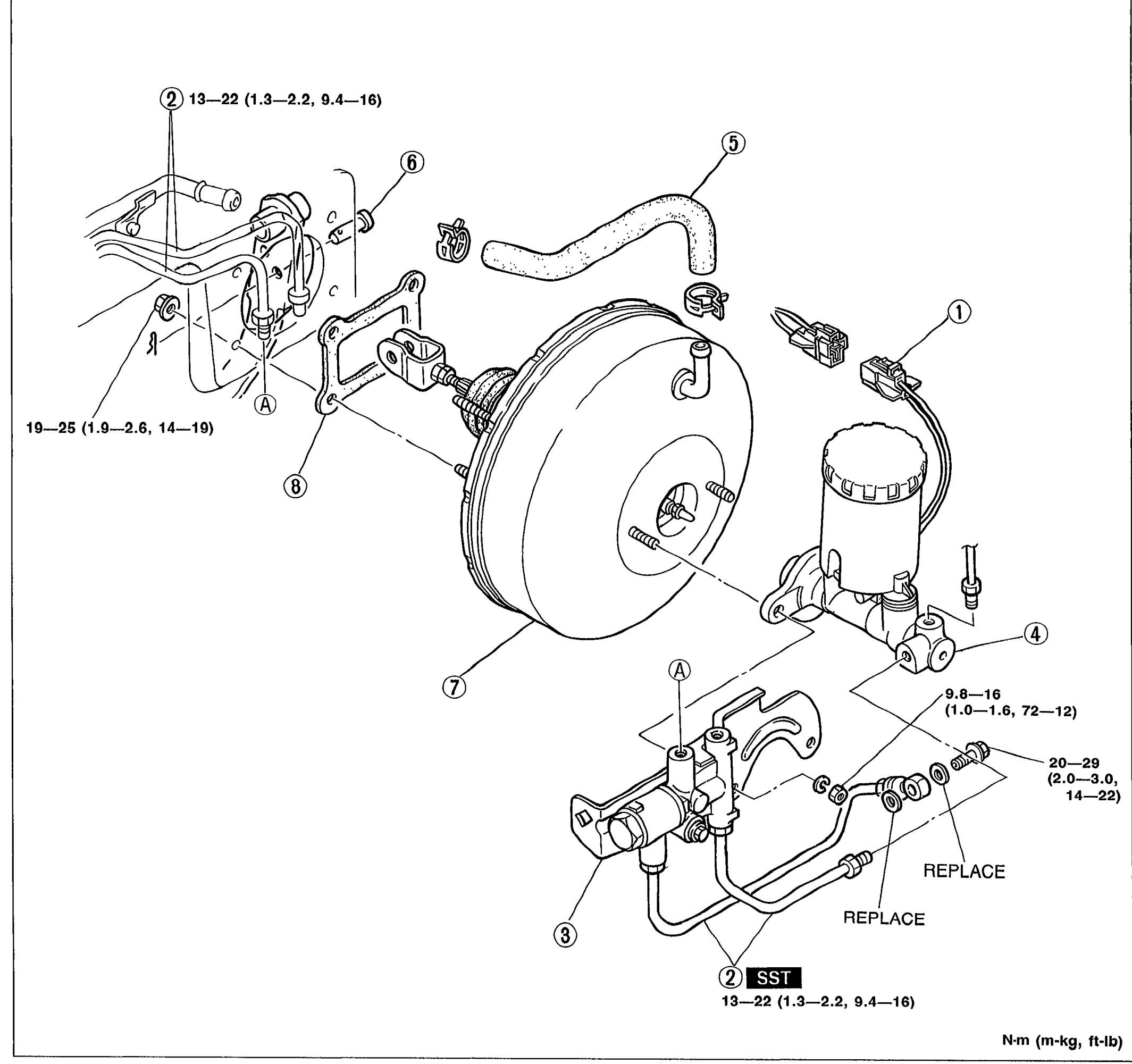
    Exploded view of the power brake unit assembly. Shows the master cylinder mounted to the brake booster (power brake unit), with vacuum hose with check valve, proportioning valve, brake pipes, clevis pin, gasket, and fluid level sensor connector. Numbered callouts 1-8 identify components. Letter callouts (A) and (B) appear near torque-stamped fasteners. Tightening torques are shown in N·m (m-kg, ft-lb). An SST marker appears at the bottom near the proportioning valve fitting. REPLACE notes mark two flare-nut fittings.
    05U0PX-029
  2. 2
    Install in the reverse order of removal.
  3. 3
    Take the following steps after installation: (1) Check and adjust the push rod and piston clearance. (Refer to page P-11.) (2) Add fluid and bleed the air. (Refer to page P-6.) (3) Check all parts for fluid leakage. (4) Make an on-vehicle check of the unit. (Refer to page P-13.) (5) Check that the vacuum hose does not contact other parts.
Parts DiagramFig. fig1
#Part NameNotes
1Fluid level sensor connector
2Brake pipeTightening torque: 13—22 N·m (1.3—2.2 m-kg, 9.4—16 ft-lb); SST used
3Proportioning valve
4Master cylinderTightening torque: 9.8—16 N·m (1.0—1.6 m-kg, 72—12 in-lb [as printed]); 20—29 N·m (2.0—3.0, 14—22) for flare nuts; REPLACE flare nut fittings
5Vacuum hose with check valve
6Clevis pinApply grease
7Power brake unitTightening torque: 19—25 N·m (1.9—2.6 m-kg, 14—19 ft-lb)
8GasketApply sealant to gasket contact surface

Search Manual

Search pages, specs, and procedures