Mazda MX-5 NA silhouetteMX-5 NA

FRONT BUMPER

S-24parts diagram

COMPONENTS

Removal / Installation

Removal / Installation

  1. 1
    Disconnect the negative battery cable.
  2. 2
    Remove in the order shown in the figure.
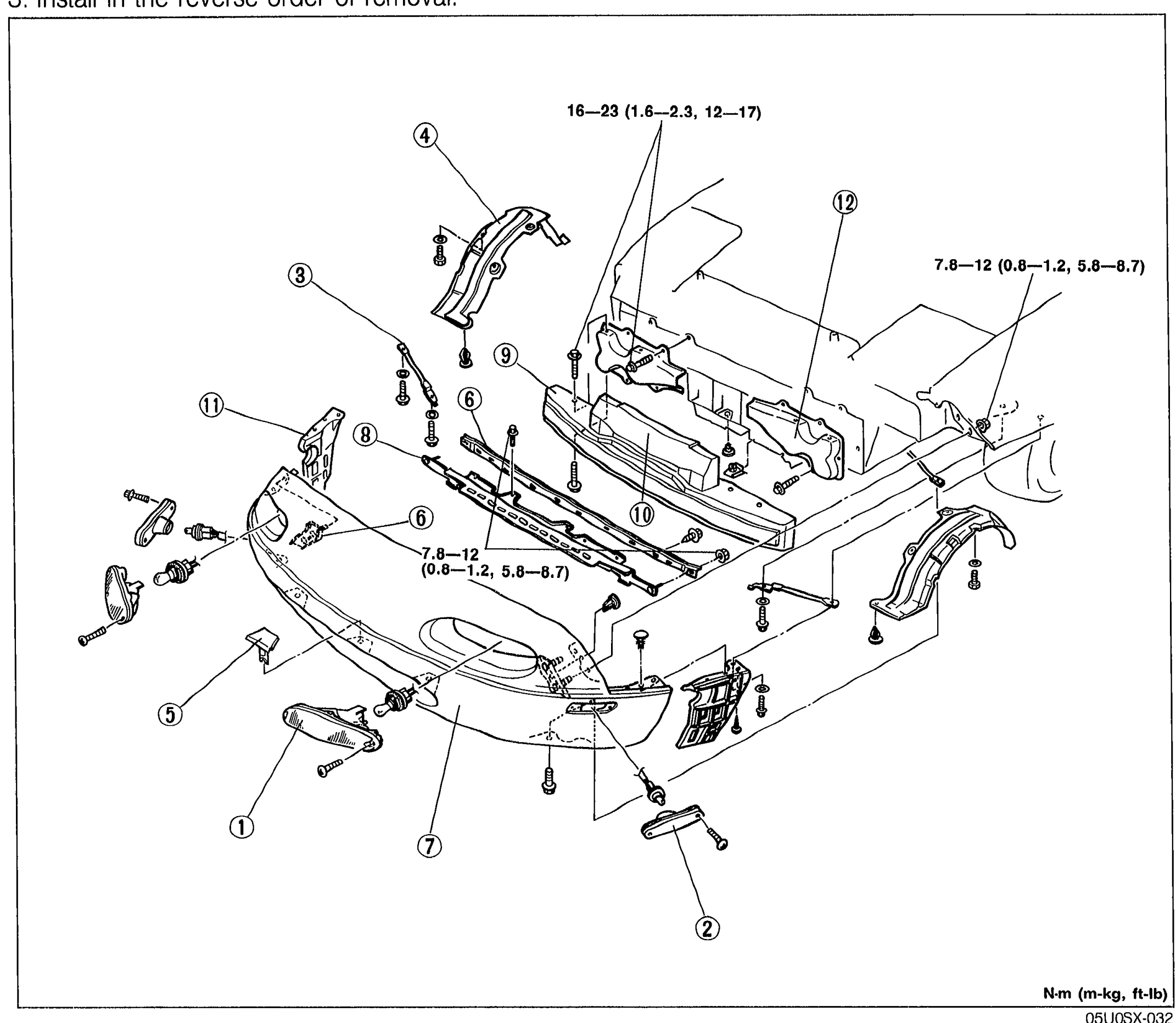
    Exploded front-three-quarter view of the MX-5 front bumper and surrounding components. Twelve numbered callouts: front combination light (1), front side marker light (2), fender bracket (3), mud guard (4), grille cover (5), set plate (6), front fascia (7), retainer (8), bumper reinforcement (9), spacer (10), front bumper retainer (11), front bumper bracket (12). Two torque-spec tags: '16—23 (1.6—2.3, 12—17)' near the top mount and '7.8—12 (0.8—1.2, 5.8—8.7)' near the lower mount and second tag near front fascia. Units N·m (m-kg, ft-lb).
    05U0SX-032
  3. 3
    Install in the reverse order of removal.
Bumper reinforcement
16 - 23N·m
Bumper mounting
7.8 - 12N·m
Parts DiagramFig. fig1
#Part NameNotes
1Front combination lightRemoval .............. Section T
2Front side marker lightRemoval .............. Section T
3Fender bracket
4Mud guard
5Grille cover
6Set plate
7Front fascia
8Retainer
9Bumper reinforcement
10Spacer
11Front bumper retainer
12Front bumper bracket

See also

Search Manual

Search pages, specs, and procedures