
TROUBLESHOOTING GUIDE — Magnetic clutch troubleshooting (Steps 4–7)
U-10flowchartMagnetic clutch troubleshooting (continued)
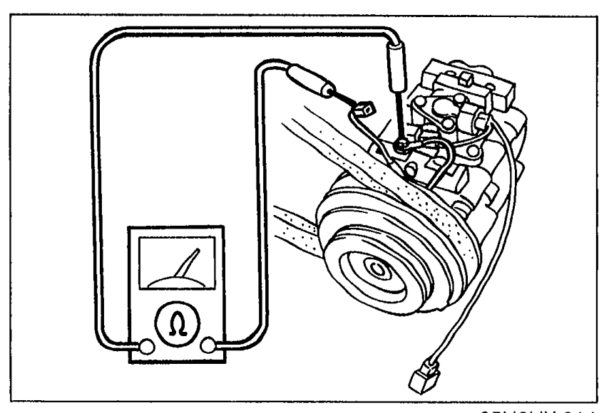
- 4Disconnect the magnetic clutch connector. Check for continuity between the magnetic clutch connector and a body ground.Set the ohmmeter to x1,000 range.If there is no continuity, replace the magnetic clutch.If there is continuity, adjust the magnetic clutch clearance or check the compressor for internal trouble.
 05U0UX-014
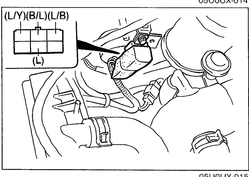
 - 5Start the engine. Turn the blower and A/C switches ON. Measure the voltage at the following terminal-wires of the A/C relay connector.
 05U0UX-015
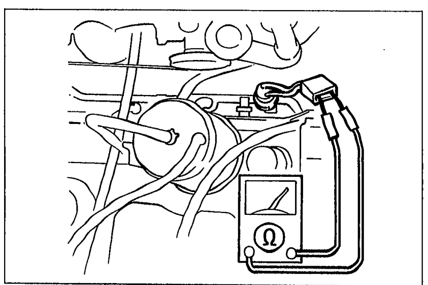
 - 6Disconnect the refrigerant pressure switch connector. Check continuity of the refrigerant pressure switch.
 05U0UX-016
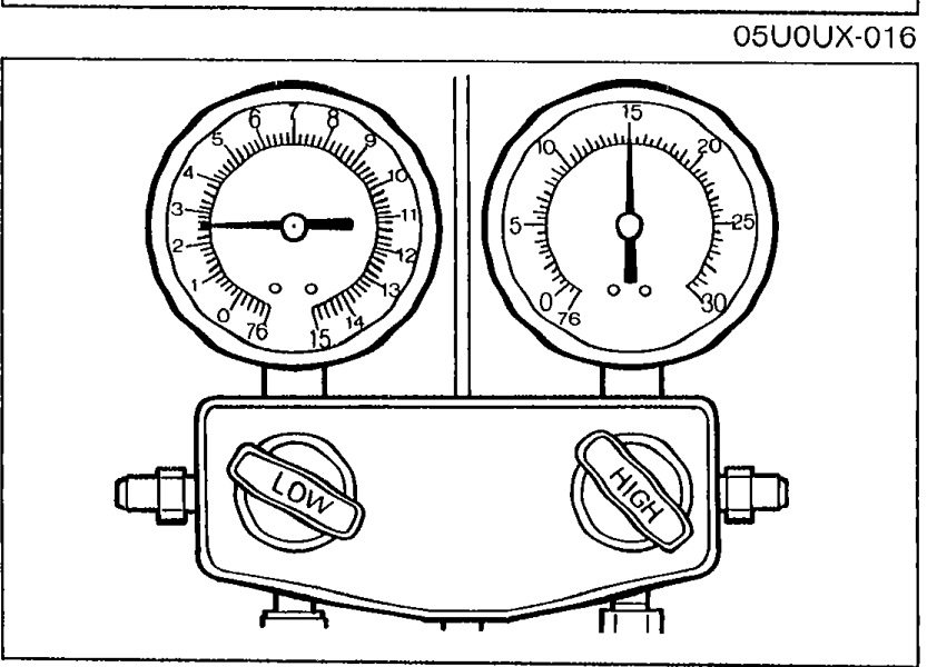
 - 7Measure the refrigerant pressure. (Refer to page U-31.)If not as specified, check the refrigerant system by referring to the troubleshooting information on page U-12.If correct, replace the refrigerant pressure switch.
 05U0UX-017
Step 5 — A/C relay connector voltages
(B/L)
Voltage12V
ActionGo to Step 6
(B/L)
Voltage0V
ActionNext, check wire (L/Y)
(L/Y)
Voltage12V
ActionNext, check wire (L/G)
(L/Y)
Voltage0V
ActionRepair wire (L/G) (AD FAN 20A fuse—A/C relay)
(L)
Voltage12V
ActionNext, check wire (L/B)
(L)
Voltage0V
ActionRepair wire (L/G) (WIPER 20A fuse—A/C relay)
(L/B)
Voltage12V
ActionCheck ECU terminal voltage
(L/B)
Voltage0V
ActionReplace A/C relay
Step 6 — Refrigerant pressure switch continuity
Yes
ActionRepair wiring harness (A/C relay—Refrigerant pressure switch—Magnetic clutch)
No
ActionGo to Step 7
| Specification | Value |
|---|---|
| Normal pressure — Low-pressure sideRefrigerant pressure measurement | 147—294 kPa (1.5—3.0 kg/cm², 21—43 psi)kPa / kg/cm² / psi |
| Normal pressure — High-pressure sideRefrigerant pressure measurement | 1,177—1,619 kPa (12.0—16.5 kg/cm², 171—235 psi)kPa / kg/cm² / psi |
Normal pressure — Low-pressure sideRefrigerant pressure measurement
147—294 kPa (1.5—3.0 kg/cm², 21—43 psi)kPa / kg/cm² / psi
Normal pressure — High-pressure sideRefrigerant pressure measurement
1,177—1,619 kPa (12.0—16.5 kg/cm², 171—235 psi)kPa / kg/cm² / psi