
TROUBLESHOOTING GUIDE — Blower motor (Steps 3–5)
U-8prose procedureStep 3
- 1Turn the ignition switch ON.
- 2Turn the blower switch and A/C switch OFF.
- 3Measure the voltage at the terminal-wires of the resistor assembly.
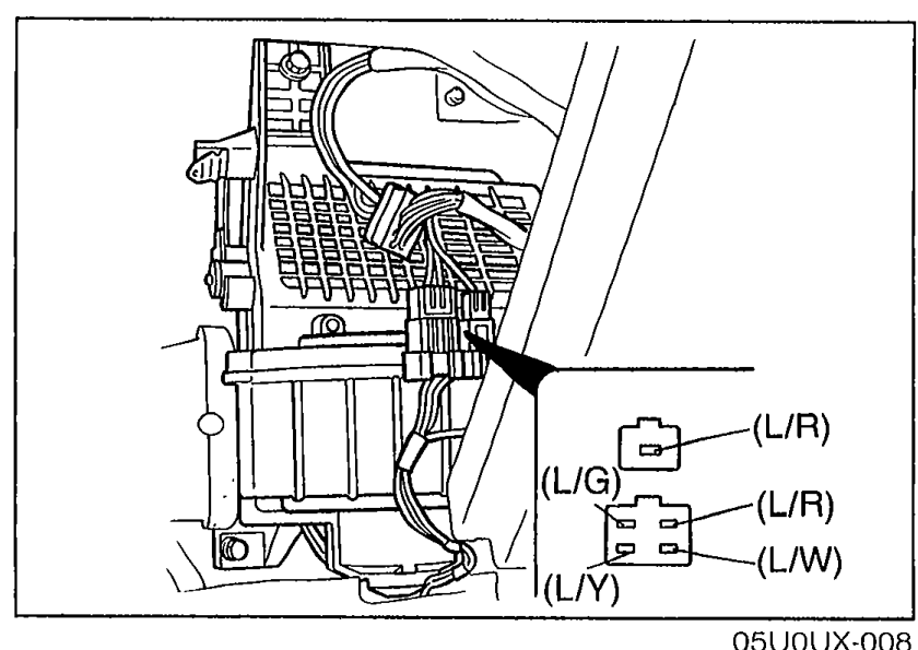 05U0UX-008
Step 3 — Resistor assembly terminal voltages
(L/R) (1-pin connector)
Voltage12V
ActionNext, check wire (L/W)
(L/R) (1-pin connector)
Voltage0V
ActionReplace blower motor
(L/W)
Voltage12V
ActionNext, check wire (L/R)
(L/W)
Voltage0V
ActionReplace resistor assembly
(L/R) (4-pin connector)
Voltage12V
ActionNext, check wire (L/G)
(L/R) (4-pin connector)
Voltage0V
ActionReplace resistor assembly
(L/G)
Voltage12V
ActionNext, check wire (L/Y)
(L/G)
Voltage0V
ActionReplace resistor assembly
(L/Y)
Voltage12V
ActionGo to Step 4
(L/Y)
Voltage0V
ActionReplace resistor assembly
Step 4
- 1Turn the ignition switch ON.
- 2Turn the blower switch to the fourth position.
- 3Measure the voltage at terminal-wire (B) of the blower switch connector.
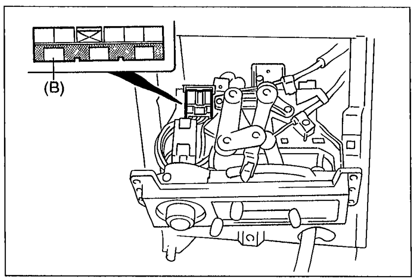 05U0UX-009
Step 4 — Blower switch terminal (B) voltage
(B)
Voltage0V
ActionGo to Step 5
(B)
Voltage12V
ActionRepair wire harness (Blower switch—Body ground)
Step 5
- 1Turn the ignition switch ON.
- 2Turn the blower switch and A/C switch OFF.
- 3Measure the voltage at the terminal-wires of the blower switch connector.
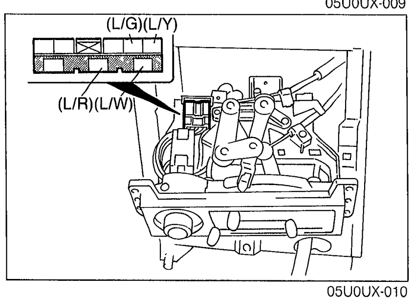 05U0UX-010
Step 5 — Blower switch terminal voltages
(L/W)
Voltage0V
ActionRepair wire harness (Resistor assembly—Blower switch)
(L/W)
Voltage12V
ActionNext, check wire (L/R)
(L/R)
Voltage0V
ActionRepair wire harness (Resistor assembly—Blower switch)
(L/R)
Voltage12V
ActionNext, check wire (L/G)
(L/G)
Voltage0V
ActionRepair wire harness (Resistor assembly—Blower switch)
(L/G)
Voltage12V
ActionNext, check wire (L/Y)
(L/Y)
Voltage0V
ActionRepair wire harness (Resistor assembly—Blower switch)
(L/Y)
Voltage12V
ActionReplace blower switch
See also
Step 4 · Step 5