
HEATER CONTROL SWITCH ASSEMBLY
U-25prose procedureInspection
Blower and A/C switch
Blower and A/C switch inspection
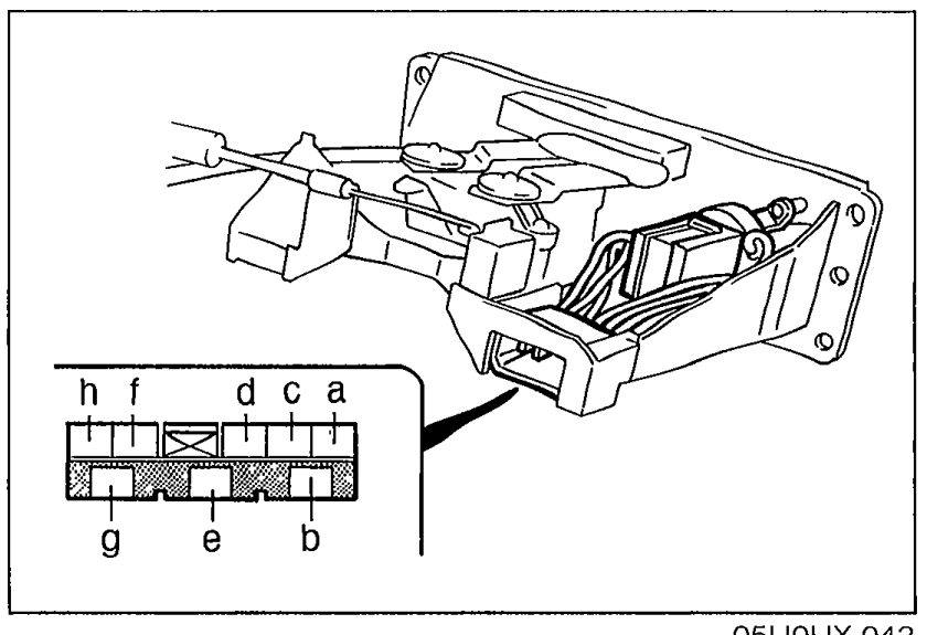
- 1Check continuity between terminals of the switch.
 05U0UX-042
 - 2If not as specified, replace the switch.
Blower and A/C switch continuity
Blower switch
PositionOFF
a
b
c
d
e
f
g
h
Blower switch
PositionFirst
aO
b
c
d
e
f
gO
hO
Blower switch
PositionSecond
aO
b
c
d
e
fO
gO
h
Blower switch
PositionThird
aO
b
c
d
eO
f
gO
h
Blower switch
PositionFourth
aO
b
c
dO
e
f
gO
h
A/C switch
PositionOFF
a
bO—diode—O
cO
d
e
f
g
h
A/C switch
PositionON
a
bO
c
d
e
f
gO
h
NOTE
O—O : Indicates continuity. O—diode—O : Indicates diode.
Adjustment
Temperature blend wire
Temperature blend wire adjustment
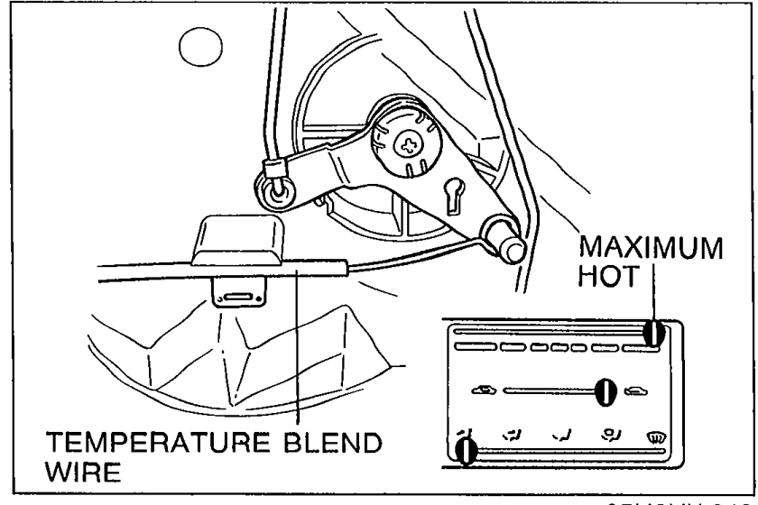
- 1Set the temperature blend lever to maximum hot position.
 05U0UX-043
 - 2Connect and clamp the wire with the shutter lever on the heater unit all the way to the right.After installation, move the temperature blend lever to be sure the wire is securely attached and that it moves the full stroke from HOT to COLD.
Airflow mode wire
Airflow mode wire adjustment
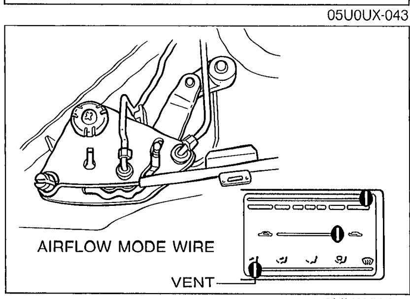
- 1Set the airflow mode control lever to VENT position.
 9MU0UX-232
 - 2Connect and clamp the wire with the shutter lever on the heater unit at its closest point.After installation, move the airflow mode control lever to be sure the wire is securely attached and that it moves the full stroke from DEF to VENT.
Rec-Fresh wire
Rec-Fresh wire adjustment
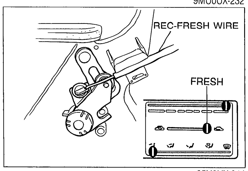
- 1Set the Rec-Fresh lever to FRESH position.
 05U0UX-044
 - 2Connect and clamp the wire with the shutter lever on the blower unit at its closest point.After installation, move the Rec-Fresh lever to be sure the wire is securely attached and that it moves the full stroke from REC to FRESH.