
AIR CONDITIONER
U-30prose procedureCharging (continued)
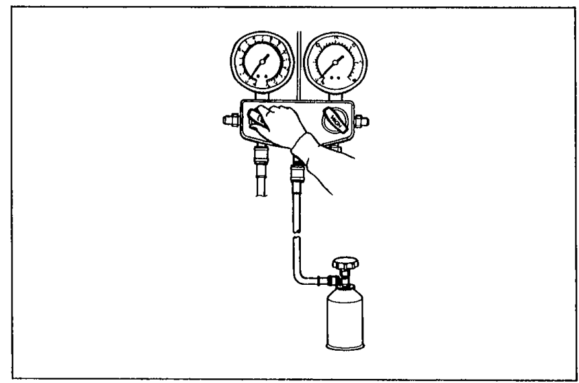
- 4Charge the system with the specified amount of refrigerant.
 05U0UX-048
 - 5Close the low-pressure manual valve and the service valve of the refrigerant container.
- 6Carry out a performance test (Refer to below).
- 7Stop the air conditioner and the engine.
- 8Quickly disconnect both hoses from the gauge fittings.
- 9Put the cap nuts on the gauge fittings.
| Specification | Value |
|---|---|
| Specified amount | 800 g (28.24 oz) |
Specified amount
800 g (28.24 oz)
Performance test
After finishing repairs, conduct a performance test of the air conditioning system as follows.
Performance test
- 1Connect the manifold gauge set. (Refer to page U-28.)
- 2Start the engine and keep the engine speed at 1,500 rpm.
- 3Operate the air conditioner at maximum cooling.
- 4Open all windows and doors.
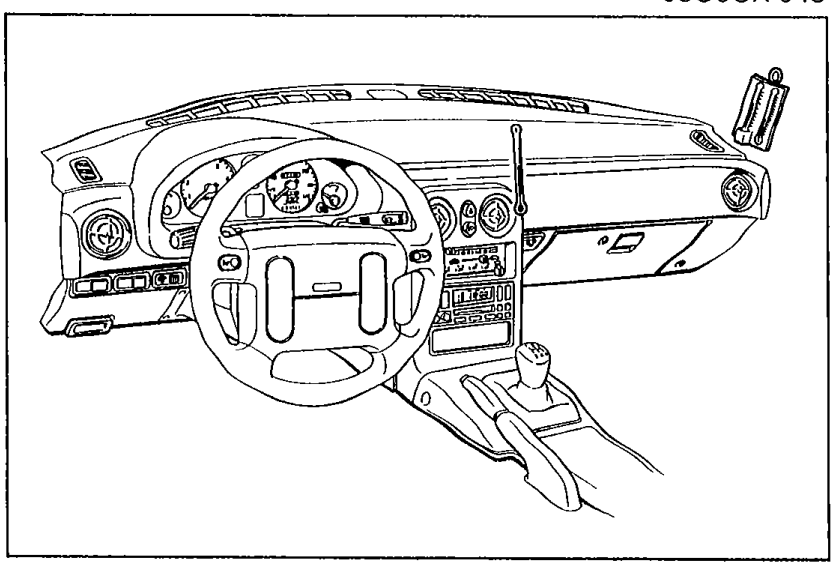
- 5Place a dry-bulb thermometer in the center ventilator outlet.
 05U0UX-049
 - 6Place the wet-bulb thermometer close to the blower inlet.
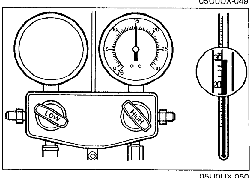
- 7Wait until the air conditioner outlet temperature stabilizes.When the high-pressure side becomes too high, pour cool water on the condenser. If it is too low, cover the front of the condenser.
 05U0UX-050
 - 8After the air conditioner stabilizes, read the dry and wet thermometer at the air inlet.
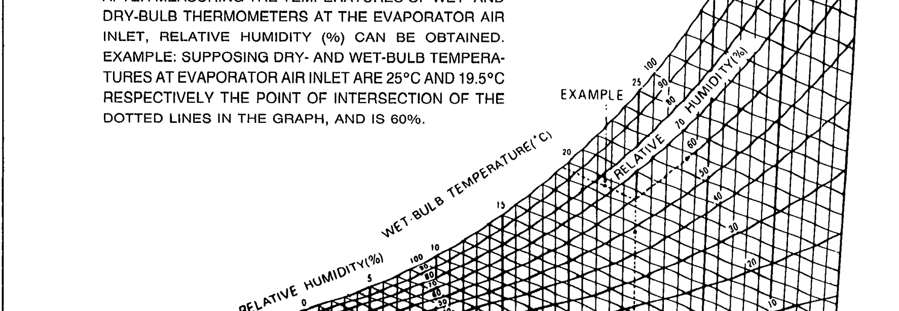
- 9Calculate the relative humidity from the chart below by comparing the wet- and dry-bulb readings.
 05U0UX-051
| Specification | Value |
|---|---|
| Blower inlet temperature | 25—35°C (77—95°F) |
| High-pressure side | 1,177—1,619 kPa (12.0—16.5 kg/cm², 171—235 psi) |
Blower inlet temperature
25—35°C (77—95°F)
High-pressure side
1,177—1,619 kPa (12.0—16.5 kg/cm², 171—235 psi)