
AIR CONDITIONER
U-28prose procedureInstallation of manifold gauge set
NOTE
Fittings for attaching the manifold gauge set are on the high- and low-pressure pipes.
Installation of manifold gauge set
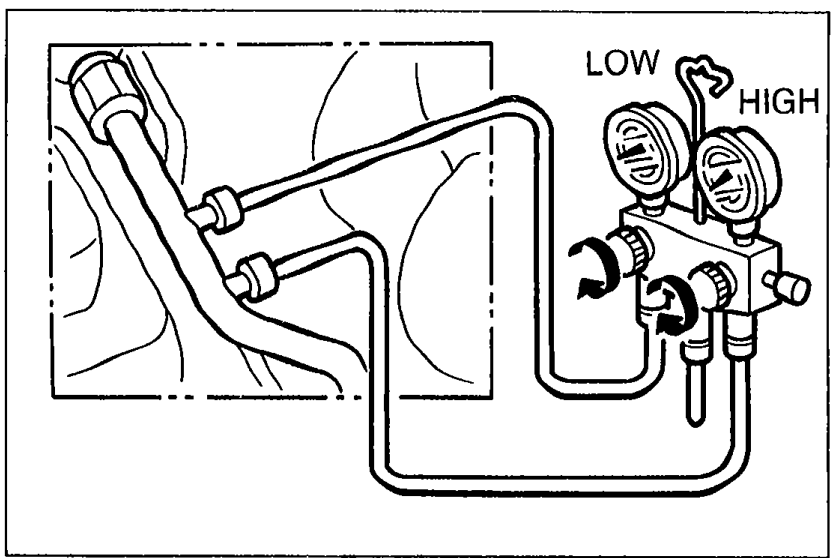
- 1Close both hand valves of the manifold gauge set.
 05U0UX-091
 - 2Connect the low-pressure hose to the low-pressure gauge fitting and high-pressure hose to the high-pressure gauge fitting.
- 3Tighten the hose nuts by hand only.
Leak test
After evacuating the system (refer to page U-29), check for leaks.
Leak test
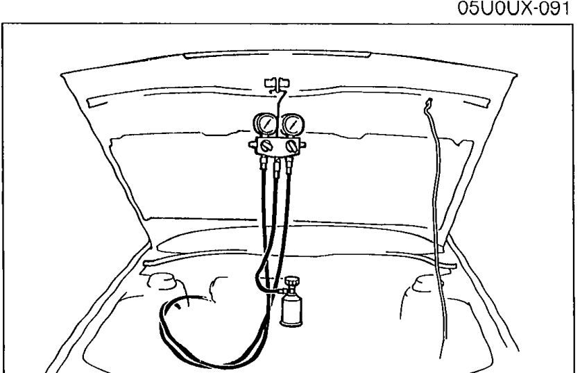
- 1Connect a full refrigerant container to the service valve.
 05U0UX-046
 - 2Open the high-pressure manual valve to charge the system with refrigerant gas.
- 3When the low-pressure gauge reads 98 kPa (1 kg/cm2, 14 psi), close the high-pressure manual valve.
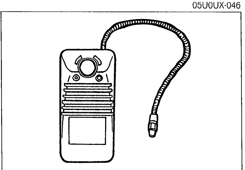
- 4Use a gas leak detector to check the system for leaks. If a leak is found, repair the faulty component or connection; then evacuate the system again.
 05U0UX-092
Discharging
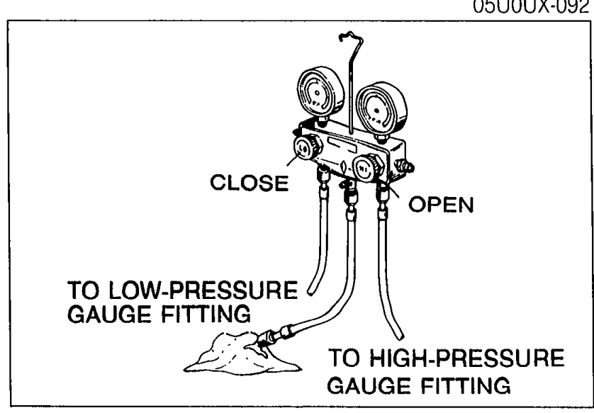
- 1Connect the manifold gauge set to the refrigeration system.
- 2Place the free end of the center hose on a shop towel.
 05U0UX-093
 - 3Slowly open the high-pressure manual valve to allow the refrigerant to escape.Open the valve only slightly. If refrigerant is allowed to escape too fast, the compressor oil will be drawn out of the system.
- 4Check the shop towel to make sure no oil is being discharged. If oil is present, partially close the manual valve.
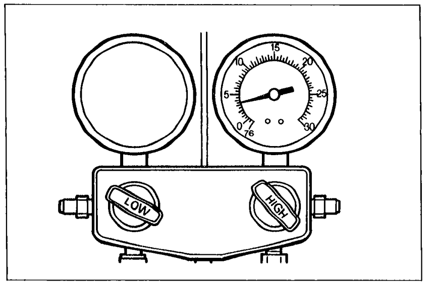
- 5After the manifold gauge reading drops below 343 kPa (3.5 kg/cm2, 50 psi), slowly open the low-pressure manual valve.
 05U0UX-094
 - 6As the system pressure drops, gradually open both the high- and low-pressure manual valves until both gauges show 0 kPa (0 kg/cm2, 0 psi).