
Joint connector & ground circuit (Federal & California)
Z-18wiring diagramFederal & California spec (49-state + California emissions).
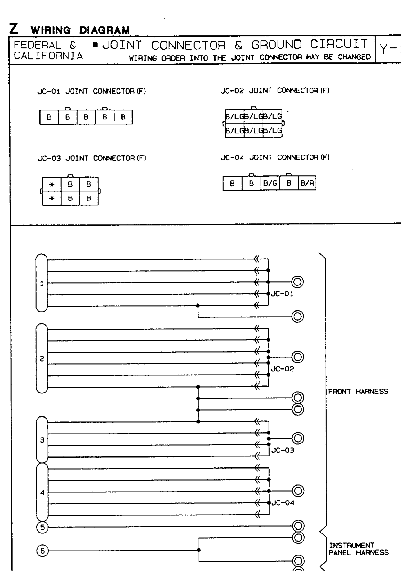
Z Wiring Diagram — Joint Connector & Ground Circuit (Federal & California)
NOTE
Wiring order into the joint connector may be changed.
Joint connectors JC-01 to JC-04 pinouts
Component LocationFig. fig1
Ground-circuit routing of joint connectors JC-01..JC-04 (groups 1–4) plus single ground points 5–7 across the FRONT HARNESS, INSTRUMENT PANEL HARNESS, and REAR HARNESS.
Y-1
11(FRONT HARNESS (feeding JC-01))
22(FRONT HARNESS (feeding JC-02))
33(FRONT HARNESS (feeding JC-03))
44(FRONT HARNESS (feeding JC-04))
55(FRONT HARNESS (single ground point))
66(INSTRUMENT PANEL HARNESS (single ground point))
77(REAR HARNESS (single ground point))