
WIRING DIAGRAM — ABS component locations (O)
Z-77wiring diagramFEDERAL & CALIFORNIA variants show O-04 (GRAY) Front-LH speed-sensor branch; CANADA variant has a separate X-05 ignition-switch routing.
Component LocationFig. fig1
Engine bay — main fuse blocks, hydraulic unit, and front speed sensors.
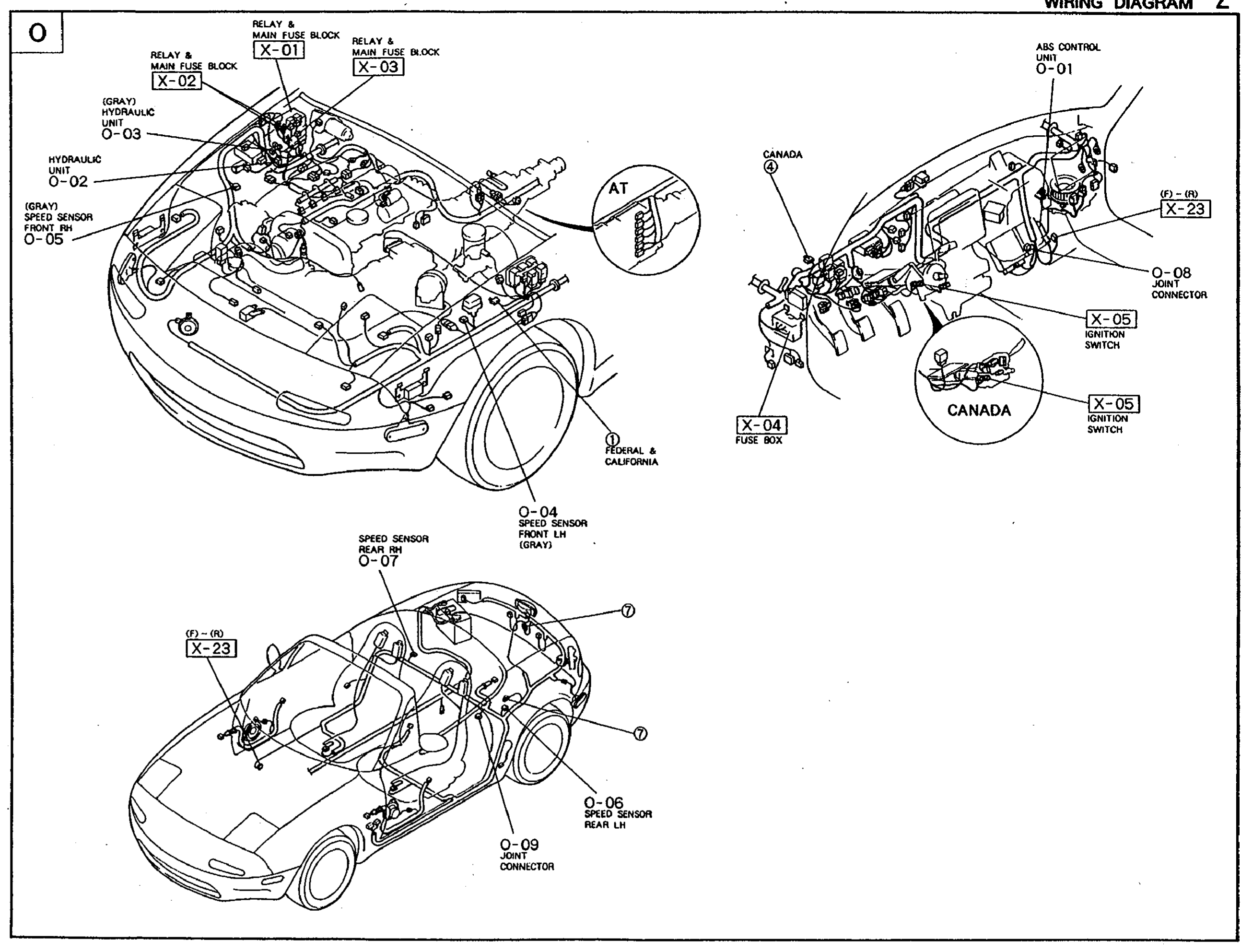
1X-01(Relay & Main Fuse Block (firewall))
2X-02((GRAY) Relay & Main Fuse Block (firewall, LH))
3X-03(Relay & Main Fuse Block (firewall))
4O-03((GRAY) Hydraulic Unit)
5O-02(Hydraulic Unit)
6O-05(Speed Sensor Front RH (GRAY))
7O-04(Speed Sensor Front LH (GRAY) — FEDERAL & CALIFORNIA only)
8A/T(A/T transmission harness branch)
Component LocationFig. fig1
Instrument panel / interior — ABS control unit, ignition switch, joint connector.
1O-01(ABS Control Unit (behind dash))
2X-23((F)-(O) in-line connector)
3O-08(Joint Connector)
4X-05(Ignition switch)
5X-04(Fuse box)
6X-05 (CANADA)(Ignition switch — Canada market variant)
Component LocationFig. fig1
Cabin / body — rear speed sensors and joint connector.
1O-07(Speed Sensor Rear RH)
2X-23((F)-(O) connector at A-pillar)
3O-06(Speed Sensor Rear LH)
4O-09(Joint Connector (floor))