
C Instrument Clusters — Connector Locations
Z-41wiring diagramFEDERAL & CALIFORNIA versus CANADA spec routing differs in the under-dash area (CANADA-only callout). AT-only inset shown in engine bay.
Connector-location pictorial showing where the 'C' instrument-clusters sub-circuit connectors and sensors are mounted on the MX-5: engine-bay sensors and Relay & Main Fuse Block (top-left view), under-dash harness connectors (top-right view), and the back of the instrument cluster + parking brake switch (lower-right view).
Component LocationFig. fig1
Connector and sensor locations on the MX-5 chassis for the C (Instrument Clusters) sub-circuit.
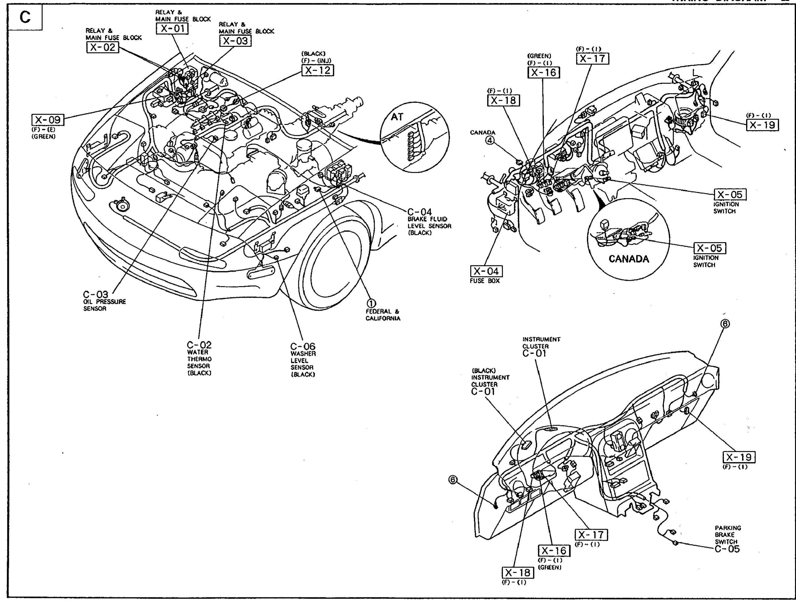
1X-01 / X-02 / X-03(Relay & Main Fuse Block in engine bay (X-03 BLACK))
2X-09(Engine-bay GREEN connector)
3X-12((F)-(GBL) inline engine-bay connector)
4C-02(Water Thermo Sensor (BLACK) on engine)
5C-03(Oil Pressure Sensor on engine)
6C-04(Brake Fluid Level Sensor (BLACK) on master cylinder reservoir)
7C-06(Washer Level Sensor (BLACK) on washer reservoir)
8X-16(Under-dash GREEN connector)
9X-17 / X-18(Under-dash harness connectors (X-18 GREEN))
10X-19(Inline connector to instrument cluster)
11X-05(Ignition switch connector)
12X-04(Fuse box connector)
13C-01(Back of instrument cluster (BLACK))
14C-05(Parking brake switch (footwell))