
WIRING DIAGRAM — Air Bag Control System component locations (S)
Z-83wiring diagramFEDERAL & CALIFORNIA market component locations for the Air Bag system.
Component LocationFig. fig1
Engine bay — fuse / relay blocks, RH D-sensor.
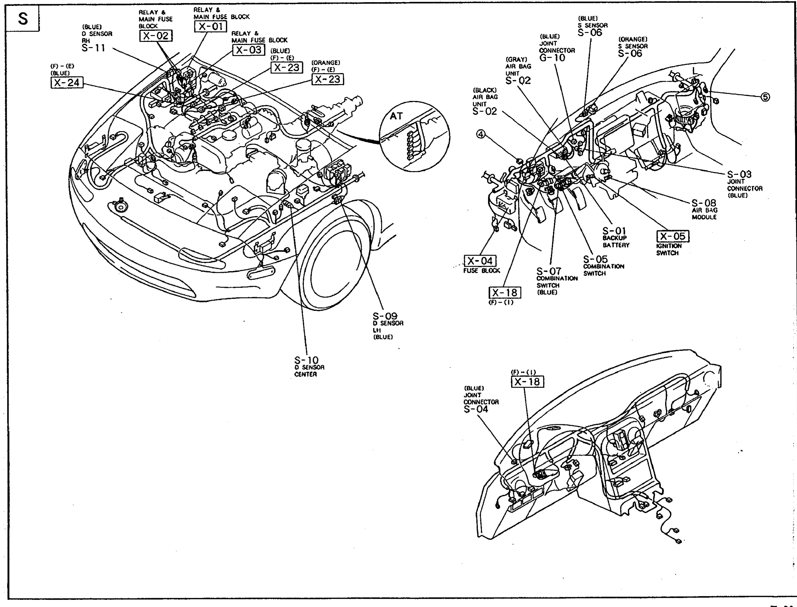
1S-11((BLUE) D Sensor RH (front RH frame rail))
2X-01(Relay & Main Fuse Block (firewall))
3X-02(Relay & Main Fuse Block (firewall LH))
4X-03((BLUE) Relay & Main Fuse Block (firewall))
5X-23((ORANGE) (F)-(I) in-line connector)
6X-24((F)-(I) in-line connector)
Component LocationFig. fig1
Underbody / front of car — LH and Center D-sensors.
1S-09((BLUE) D Sensor LH (front LH frame rail))
2S-10(D Sensor Center (under center console floor))
Component LocationFig. fig1
Dashboard / IP — air bag unit, module, S-sensor, switches.
1S-06((BLUE) S Sensor (top of dash, near firewall))
2G-10((GRAY) Joint Connector)
3S-02((BLACK) Air Bag Control Unit (behind dash, center))
4S-03(Joint Connector)
5S-05(Ignition Switch)
6S-08(Air Bag Module (in steering wheel))
7S-01(Backup Battery)
8X-04(Fuse Block)
9S-07((BLUE) Combination Switch)
Component LocationFig. fig1
Lower dash — intermediate connector and joint connector.
1X-18((BLUE) (F)-(I) in-line connector)
2S-04((BLUE) Joint Connector)