
WIRING DIAGRAM Z — Starting/Charging System Component Locations (Sheet A)
Z-27wiring diagramFederal & California shown by default; CANADA inset highlights the Canada-spec ignition-switch detail. Surya labelled the figure region as 'PageHeader'; bbox copied verbatim as the region is the page art.
Starting / Charging — Component Locations (Sheet A)
Component LocationFig. fig1
Physical locations of the Sheet-A connectors and components on the engine bay (top) and under-dash (bottom). Canada-spec ignition switch shown in inset.
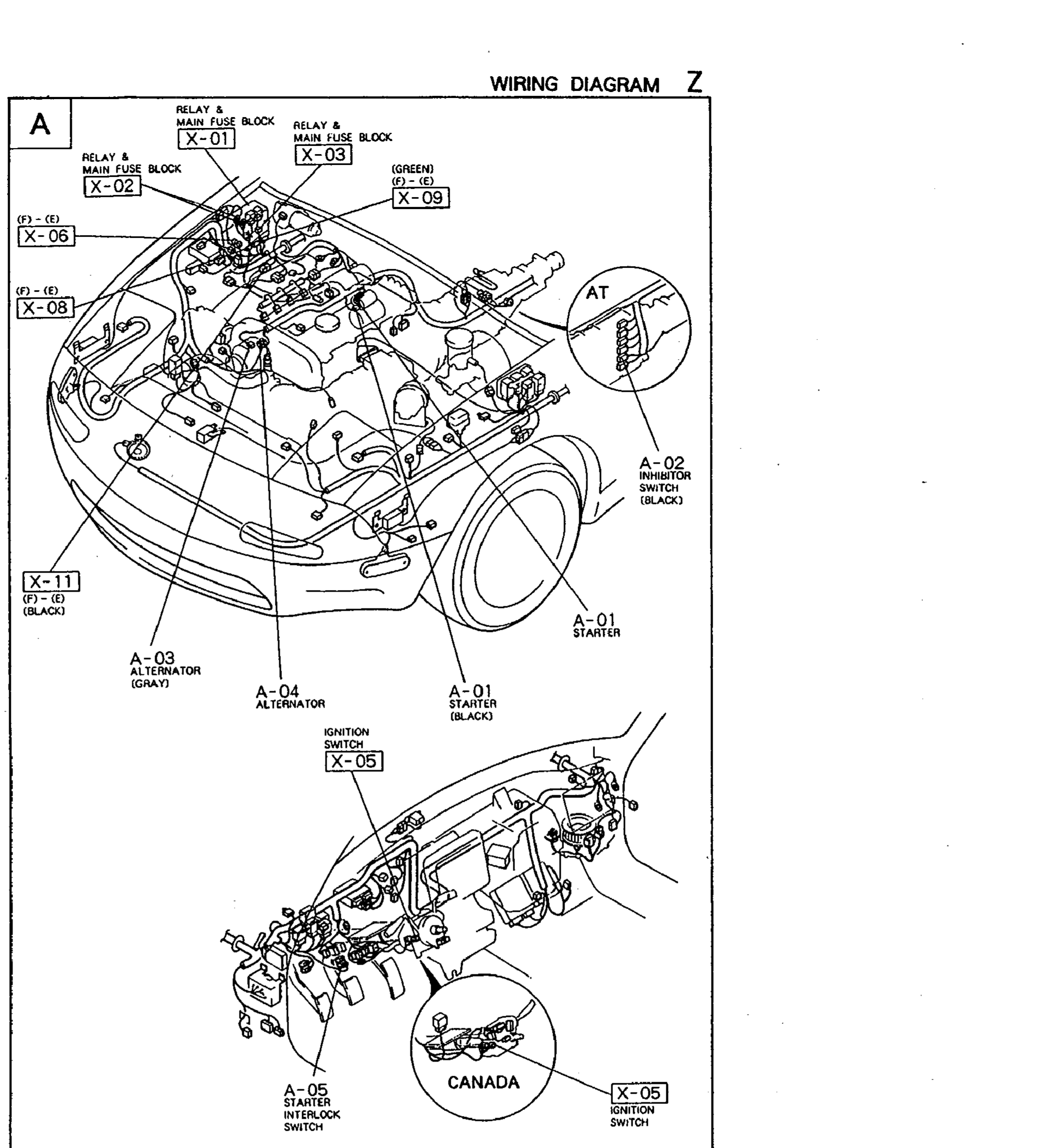
1X-01 / X-02 / X-03(Relay & main-fuse block on inner fender)
2X-06, X-08, X-11(Bulkhead / inner-fender connectors)
3X-09(Front of engine (green))
4A-01(Starter motor — black connector)
5A-02(Inhibitor switch on AT — black connector)
6A-03 / A-04(Alternator connectors (gray / unlabelled))
7X-05(Ignition switch — under dash, driver side)
8A-05(Starter interlock switch — under dash)