
Wiring Diagram - Engine Wiring Harness B-1c (Connector Locations)
Z-33wiring diagramAT-only callout for X-09/B1-22 (neutral switch); CANADA-only callout for X-16 connector and B1-21 clutch switch.
B-1c Wiring Diagram — Connector Locations
Connector-location pictorial for engine-harness sub-circuit B-1c. Left diagram (engine bay): X-09 (GREEN, 7-pin) is the neutral switch (B1-22, AT only) and B1-20 is the diagnostic connector. Right diagram (under instrument panel): X-16 (GREEN, 7-pin, CANADA) and connectors B1-01 (engine control unit) and B1-21 (clutch switch, CANADA).
Component LocationFig. fig1
Locations of engine-harness B-1c connectors on the MX-5 chassis.
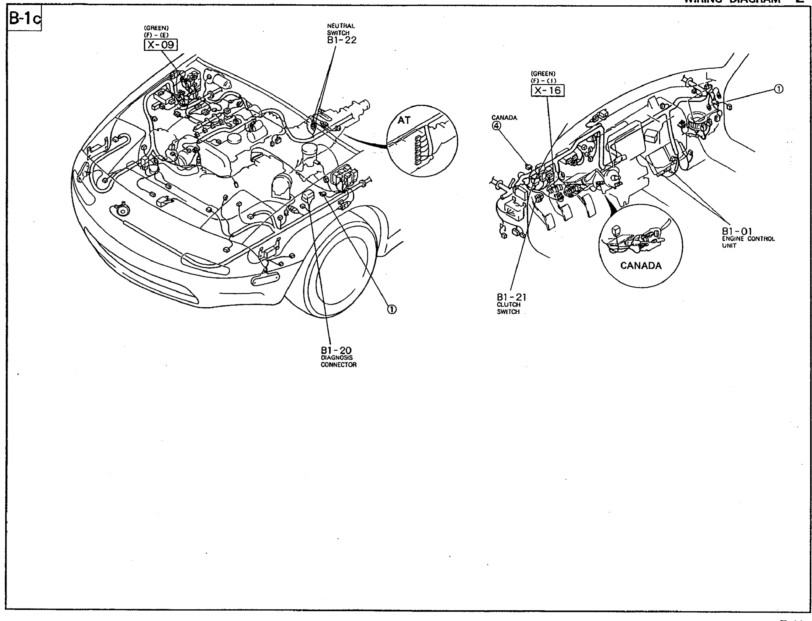
1X-09(Engine bay, near firewall (GREEN, 7-pin, NEUTRAL SWITCH B1-22, AT))
2B1-22(Neutral switch on transmission (AT))
3B1-20(Diagnostic connector, front of engine bay)
4X-16(Under instrument panel (GREEN, 7-pin, CANADA))
5B1-01(Engine control unit, right side of dash)
6B1-21(Clutch switch (CANADA))