
WIRING DIAGRAM - H-1 Component Locations
Z-63wiring diagramIncludes a Canada-specific Ignition Switch X-05 callout.
H-1 Component Locations (A/T System)
Component LocationFig. fig1
Diagrammatic location of A/T (automatic transmission) control components and associated connectors/fuse blocks on the 1990 Mazda MX-5 Miata. Three views: engine bay (left), firewall/passenger compartment (top right), and instrument panel (bottom right).
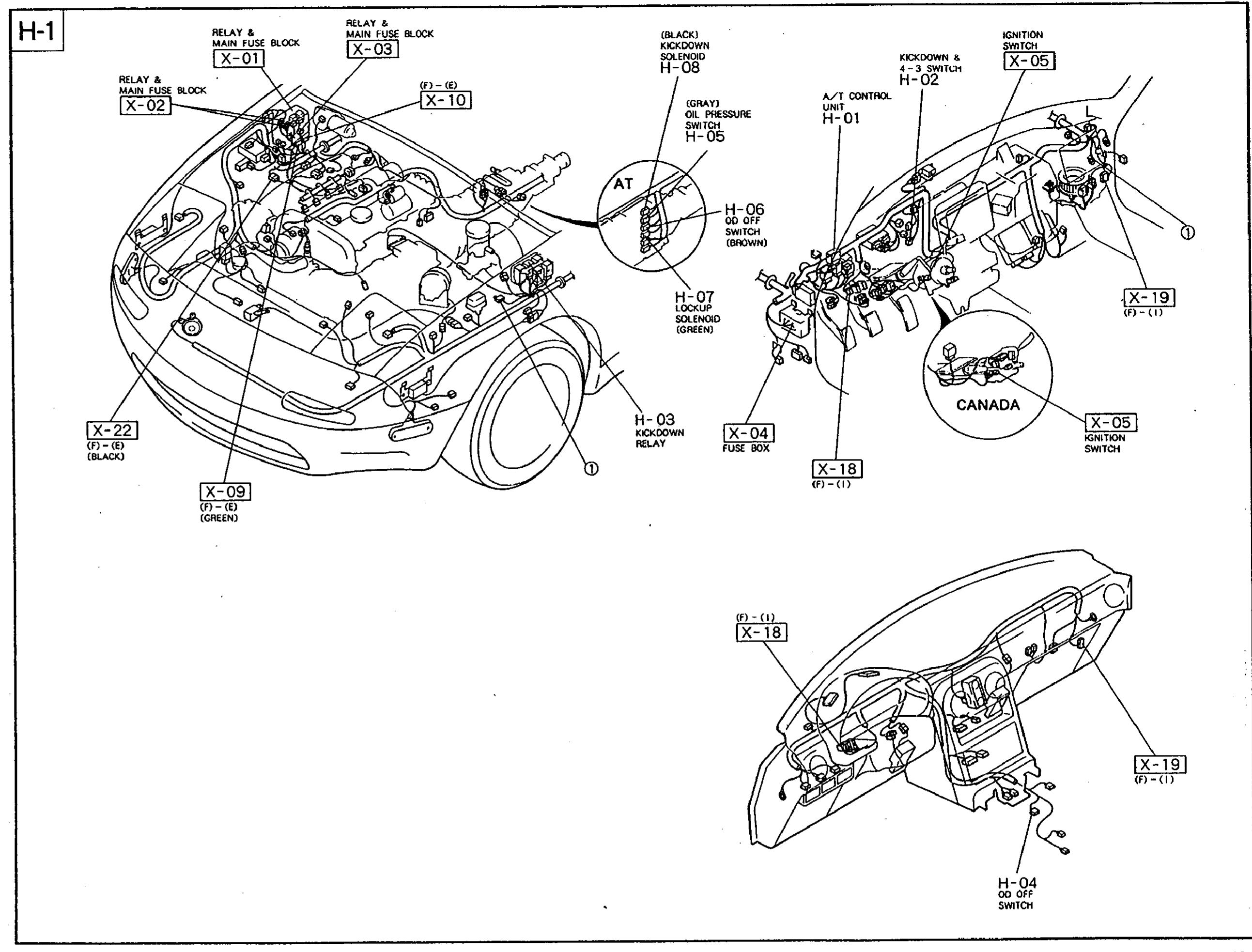
1X-01(Engine bay - Relay & Main Fuse Block)
2X-02(Engine bay - Relay & Main Fuse Block)
3X-03(Engine bay - Relay & Main Fuse Block)
4X-04(Passenger compartment - Fuse Box)
5X-05(Steering column - Ignition Switch)
6X-09(Engine bay - Connector (Green))
7X-10(Engine bay - Connector)
8X-18(Instrument panel - Connector)
9X-19(Instrument panel - Connector)
10X-22(Engine bay - Connector (Black))
11H-01(Behind A/T - A/T Control Unit)
12H-02(A/T - Kickdown & 4-3 Switch)
13H-03(Engine bay - Kickdown Relay)
14H-04(Instrument panel - OD OFF Switch)
15H-05(A/T - Oil Pressure Switch (Gray))
16H-07(A/T - Lockup Solenoid (Green))
17H-08(A/T - Kickdown Solenoid (Black))