
WIRING DIAGRAM — Power Window component locations (K)
Z-75wiring diagramCanada-market variant ignition switch routing shown separately.
Component LocationFig. fig1
Engine bay — power window related fuse/relay blocks. Front three-quarter view with hood open.
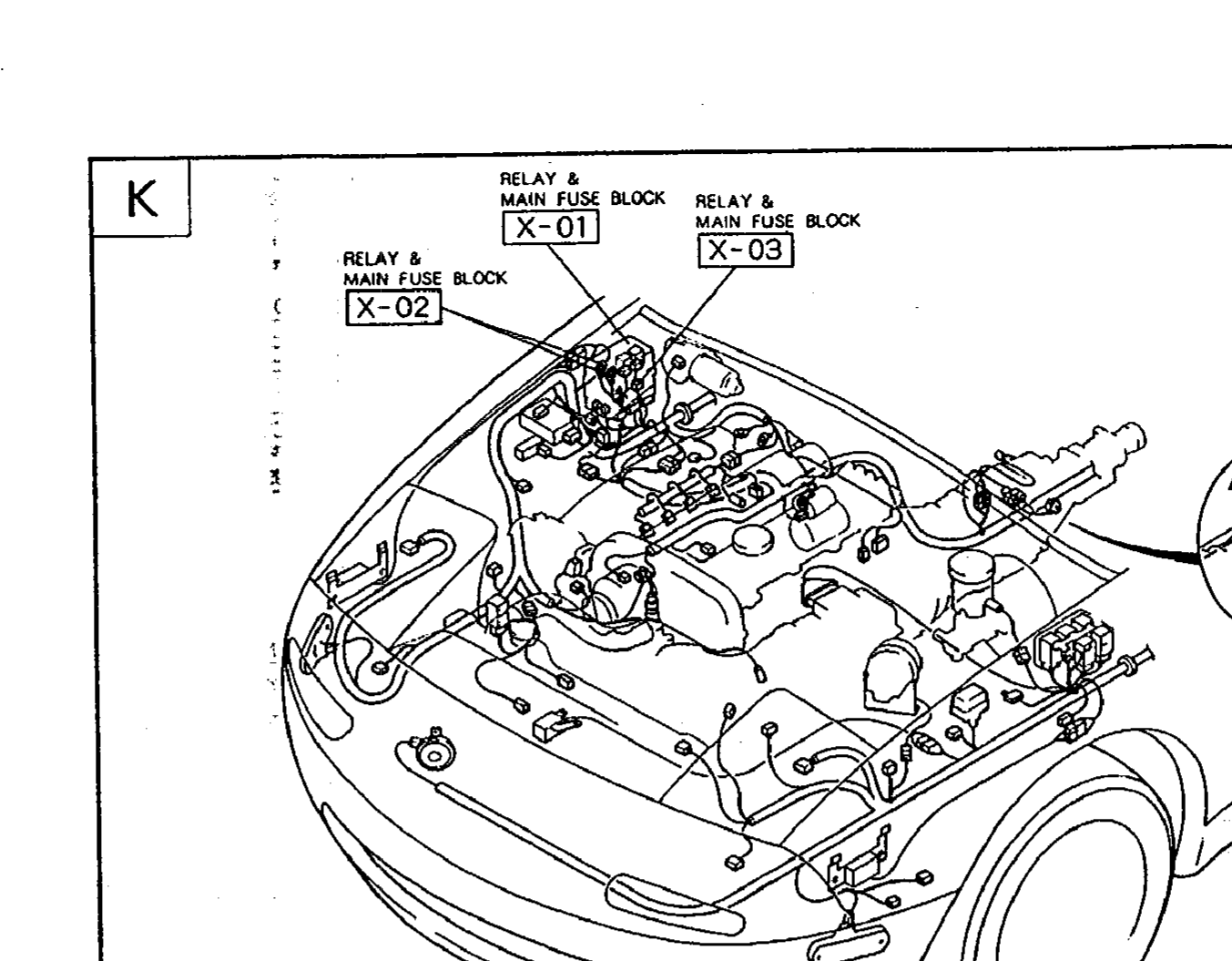
1X-01(Relay & Main Fuse Block (firewall, center))
2X-02(Relay & Main Fuse Block (firewall, LH))
3X-03(Relay & Main Fuse Block (firewall, center))
4A/T(A/T transmission harness branch)
Component LocationFig. fig2
Dashboard / instrument panel — ignition switch and main connectors.
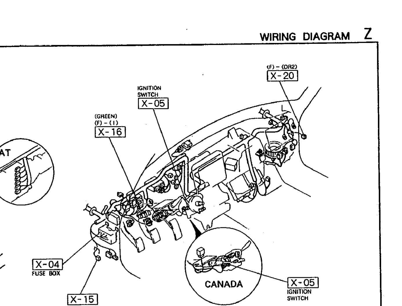
1X-05(Ignition switch)
2X-16((GREEN) (F)-(I) in-line connector)
3X-20((F)-(DR2) in-line connector)
4X-04(Fuse box)
5X-15((F)-(DR1) in-line connector)
6X-05 (CANADA)(Ignition switch — Canada market variant)
Component LocationFig. fig3
Body harness routing for LH and RH power window motors.
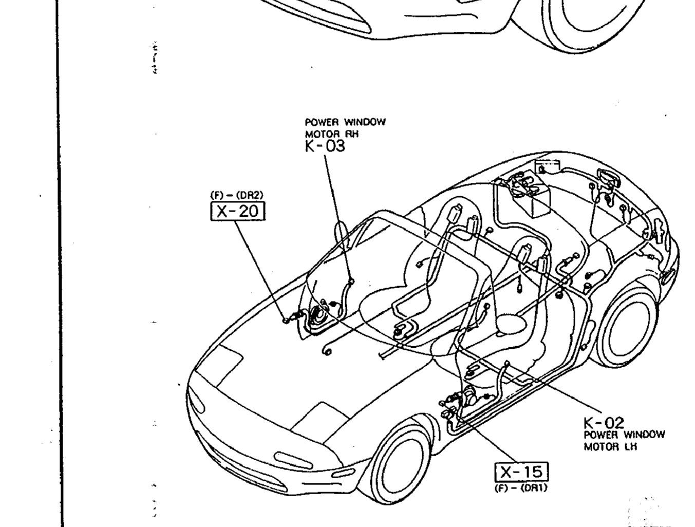
1K-03(Power Window Motor RH (in RH door))
2X-20((F)-(DR2) door connector at A-pillar)
3K-02(Power Window Motor LH (in LH door))
4X-15((F)-(DR1) door connector at A-pillar)
Component LocationFig. fig4
Instrument panel underside — main switch and intermediate connectors.
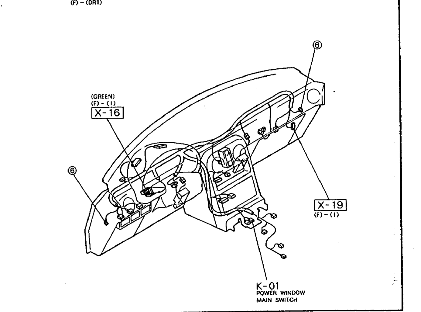
1X-16((GREEN) (F)-(I) in-line connector behind dash)
2X-19((F)-(I) in-line connector behind dash)
3K-01(Power Window Main Switch (center console))