
WIRING DIAGRAM Z — Engine Control / Ignition System Component Locations (Sheet B-1a)
Z-29wiring diagramX-11 connector color varies by transmission: BROWN on AT, BLACK on MT. Federal & California / Canada splits noted inline.
Engine Control / Ignition System — Component Locations (Sheet B-1a)
Component LocationFig. fig1
Physical locations on the engine bay (left) and under-dash (right). AT-only inset and Federal & California / Canada variants are tagged inline.
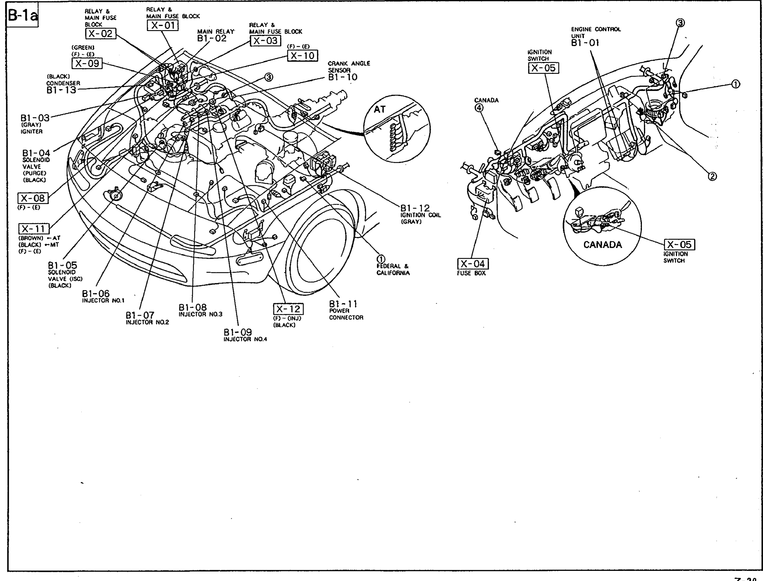
1X-01 / X-02 / X-03(Relay & main fuse block on left strut tower)
2B1-02(Main relay inside the relay & main fuse box)
3X-09 / X-10(Bulkhead connectors near the relay box)
4X-08, X-11(Bulkhead connectors on left fender)
5B1-01(Engine control unit — firewall, under dash)
6B1-03(Igniter — left side of engine)
7B1-04 / B1-05(Solenoid valves (purge / ISC) on intake area)
8B1-06 … B1-09(Fuel injectors on intake manifold)
9B1-10(Crank angle sensor on engine)
10B1-11(Power connector)
11B1-12(Ignition coil — gray)
12B1-13(Condenser — black)
13X-12(T1-OUT bulkhead connector, black)
14X-04 / X-05(Fuse box / ignition switch — under-dash, driver side)