
Joint Connector & Ground Component Location
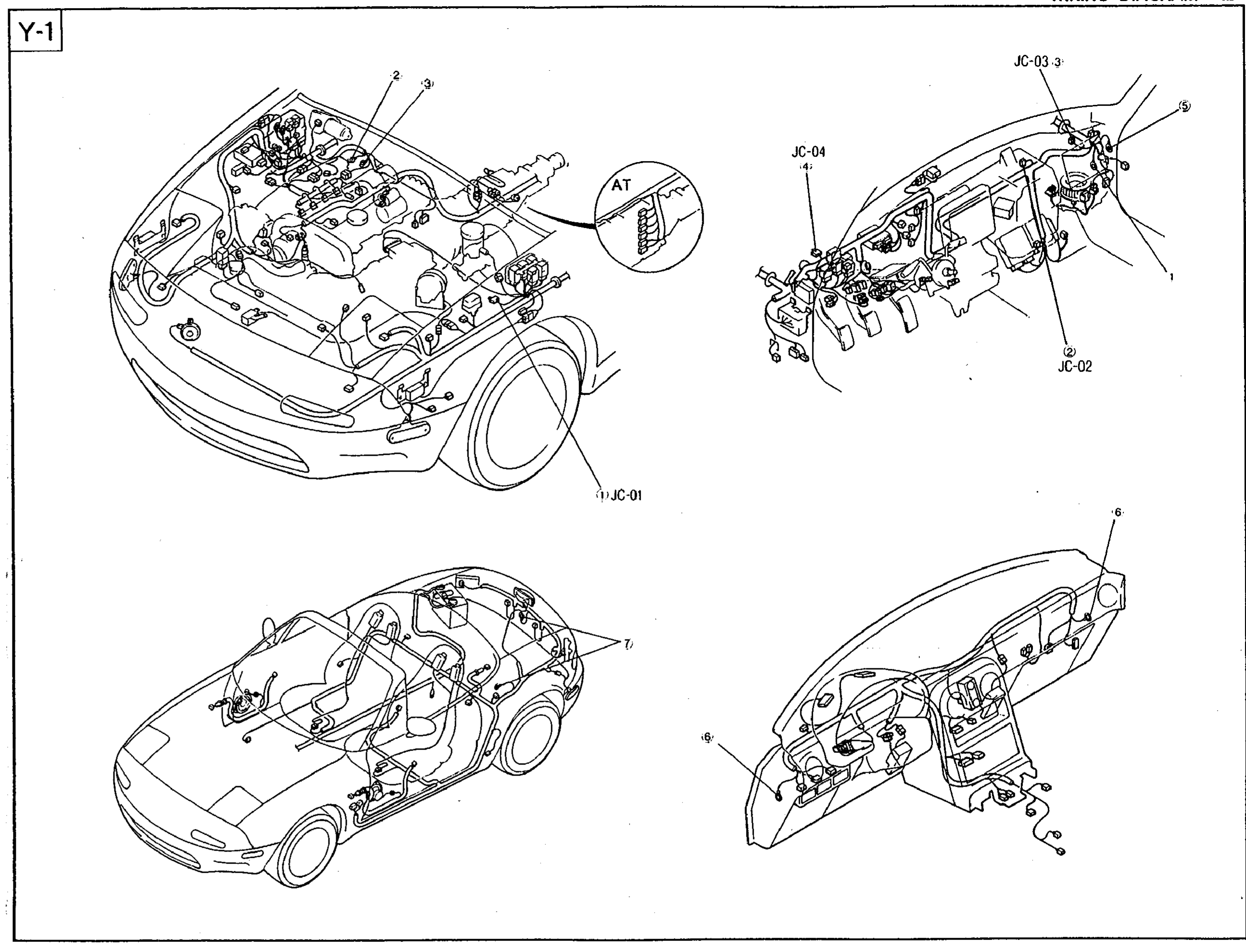
Z-19wiring diagramA/T-only ground location is called out separately via the 'AT' inset detail in the engine-bay view.
WIRING DIAGRAM
Component LocationFig. fig1
Vehicle component-location chart Y-1 identifying joint connectors JC-01, JC-02, JC-03, JC-04 and associated ground points across the engine bay, instrument panel, and body interior. Used as the visual key for the joint connector & ground circuit diagram on the following page.
Y-1
11(Front fender / engine bay — JC-01)
22(Engine-bay ground)
33(Engine-bay ground)
4AT(A/T-only inset (engine bay))
5JC-02(Instrument panel)
6JC-03(Instrument panel (upper))
7JC-04(Instrument panel (left))
85(Instrument panel reverse)
96(Instrument panel reverse)
107(Body interior / rear ground)