
WIRING DIAGRAM - H-2 Component Locations (Shiftlock System)
Z-67wiring diagramCanada-spec Ignition Switch X-05 callout included.
H-2 Component Locations (Shiftlock System)
Component LocationFig. fig1
Three-view component-location diagram (engine bay, firewall, instrument panel) for the A/T Shiftlock System on the 1990 Mazda MX-5 Miata.
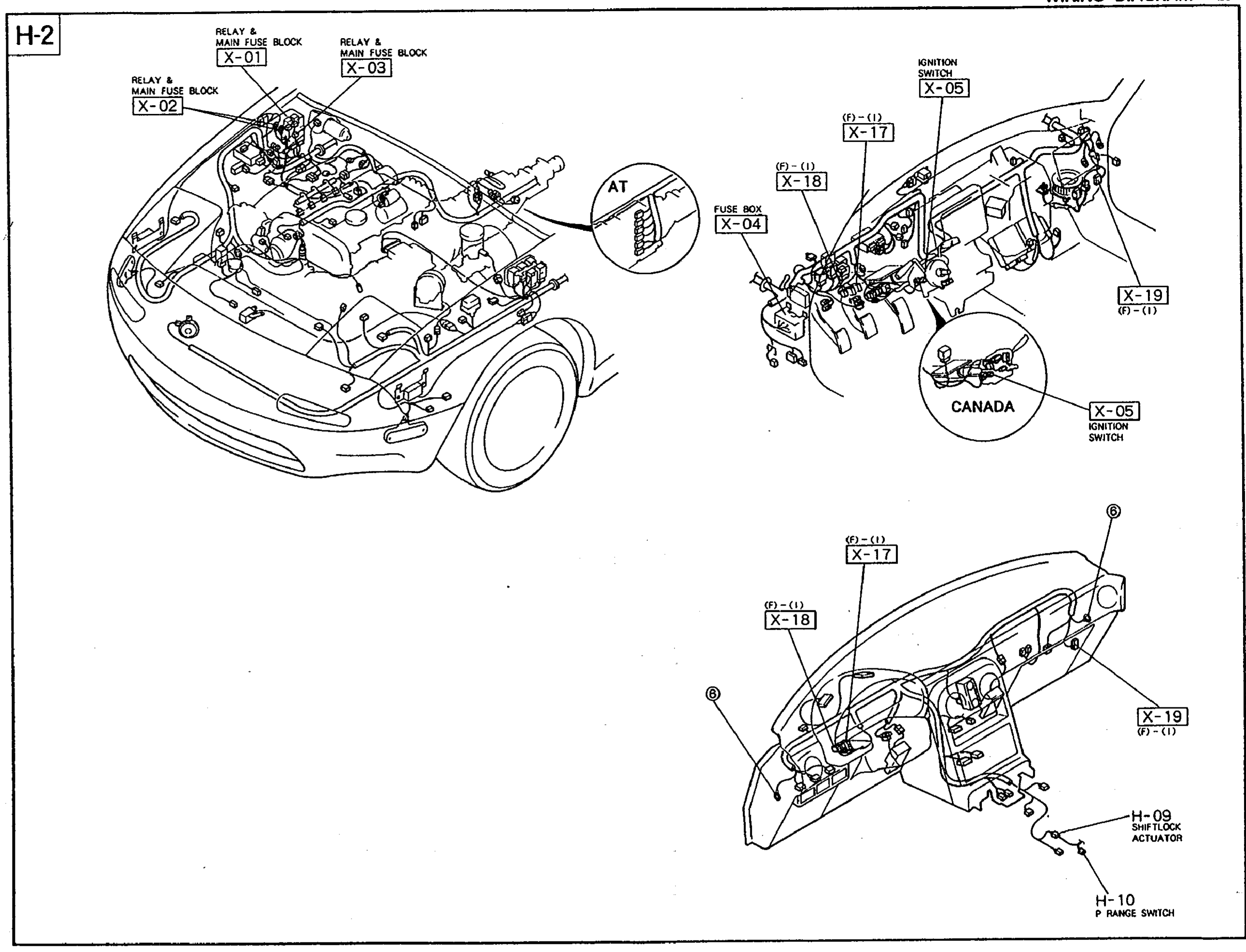
1X-01(Engine bay - Relay & Main Fuse Block)
2X-02(Engine bay - Relay & Main Fuse Block)
3X-03(Engine bay - Relay & Main Fuse Block)
4X-04(Passenger side firewall - Fuse Box)
5X-05(Steering column - Ignition Switch (incl. Canada variant))
6X-17(Dash harness - Connector)
7X-18(Dash harness - Connector)
8X-19(Dash harness - Connector)
9H-09(Instrument panel - Shiftlock Actuator)
10H-10(Instrument panel - P Range Switch)