
WIRING DIAGRAM — T section component locations
Z-85wiring diagramFEDERAL & CALIFORNIA vs CANADA market-variant differences shown for engine-bay and ignition-switch locations.
WIRING DIAGRAM — Section T component locations
Component LocationFig. fig1
Locations of T-section wiring components (CPU sound warning unit, ignition key reminder switch, buckle switch) and the connectors / fuse blocks they tie into. Engine-bay relay & main fuse block locations differ between FEDERAL & CALIFORNIA and CANADA variants; the CANADA variant uses ignition switch X-05.
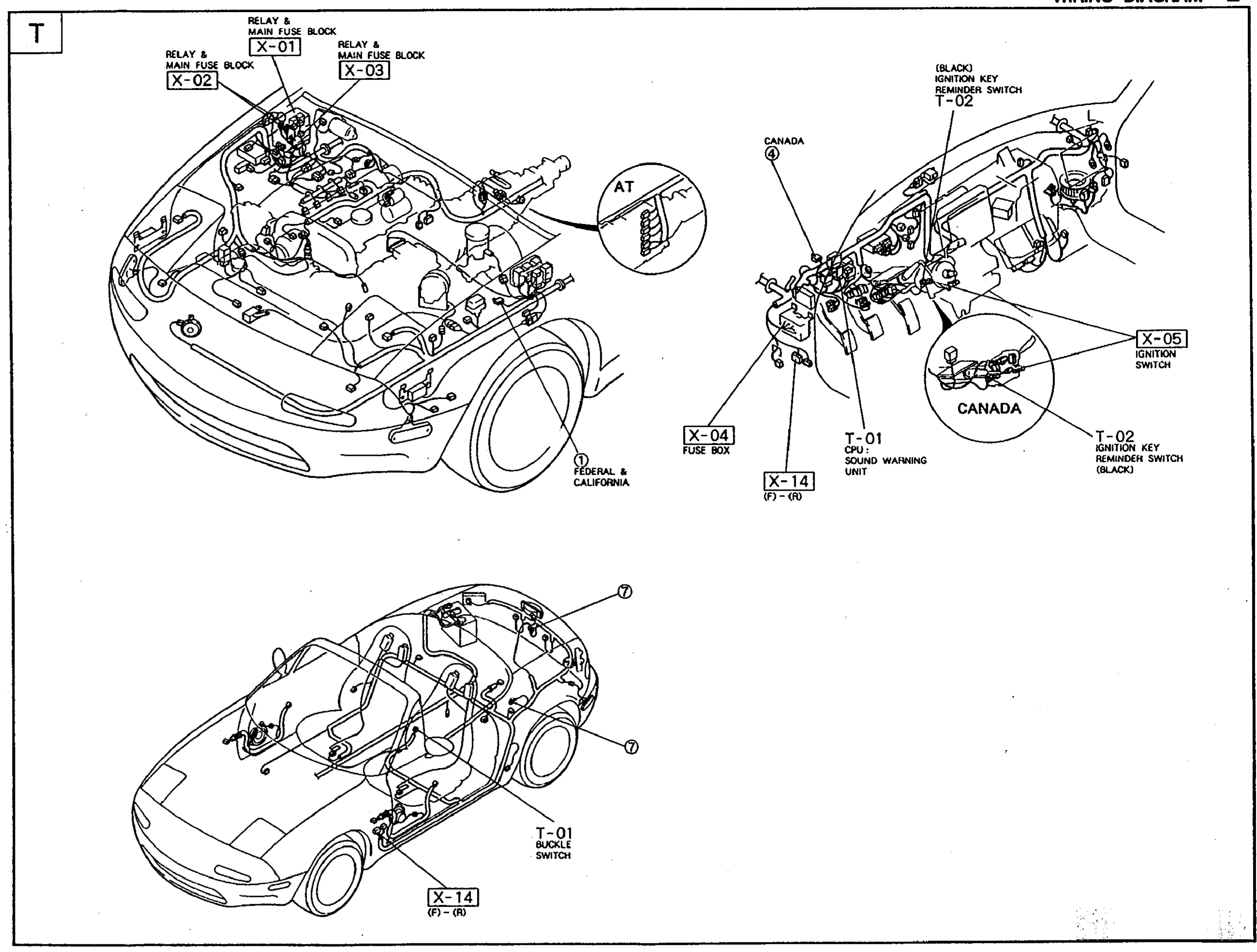
1X-01(Engine bay — relay & main fuse block)
2X-02(Engine bay — relay & main fuse block)
3X-03(Engine bay — relay & main fuse block)
4T-02(Ignition key reminder switch (Black))
5X-04(Fuse box, behind dashboard)
6X-05(Ignition switch (Canada))
7T-01 (CPU)(CPU sound warning unit, IP area)
8X-14(Connector X-14, IP/dash harness)
9T-01 (Buckle)(Buckle switch, driver's seat belt)
10X-14 (interior)(Connector X-14, interior floor harness)
NOTE
FEDERAL & CALIFORNIA variant.
CANADA variant uses ignition switch X-05 and ignition key reminder switch T-02 (black).
See also
X-01 · X-02 · X-03 · X-04 · X-05 · X-14 · T-01 · T-02