
WIRING DIAGRAM — Cruise Control System component locations (Q)
Z-79wiring diagramComposite shows engine bay, IP behind dash, and lower-dash interior in one frame.
WIRING DIAGRAM — Cruise Control component locations
Component LocationFig. fig1
Engine bay — fuse / relay blocks and cruise actuator.
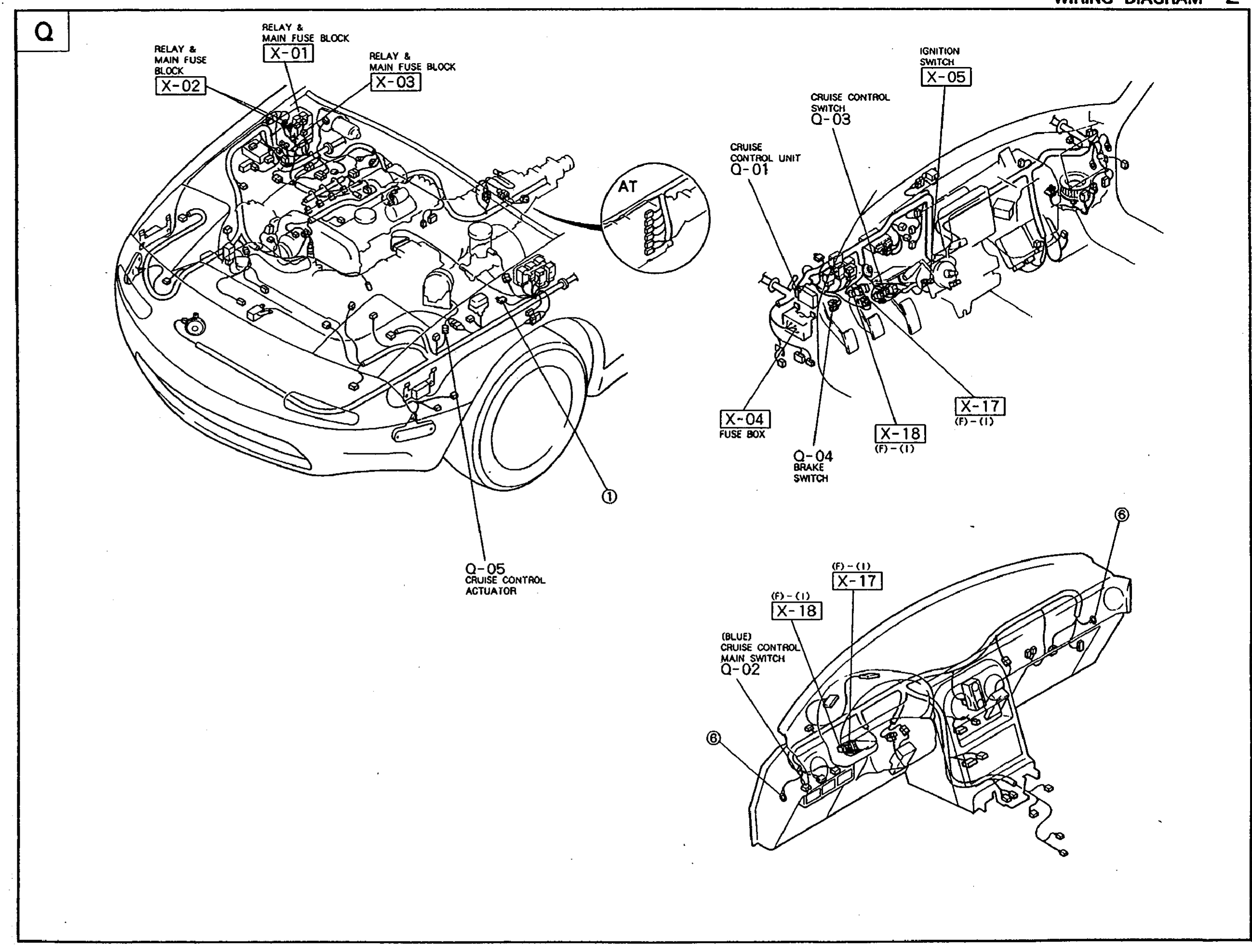
1X-01(Relay & Main Fuse Block (firewall center))
2X-02(Relay & Main Fuse Block (firewall LH))
3X-03(Relay & Main Fuse Block (firewall))
4Q-05(Cruise Control Actuator (LH fender))
5A/T(A/T harness branch)
Component LocationFig. fig1
Dashboard / IP — ignition switch, cruise unit, cruise switch on steering wheel.
1X-05(Ignition Switch)
2Q-03(Cruise Control Switch (steering-wheel mount))
3Q-01(Cruise Control Unit (behind dash))
4X-04(Fuse Box)
5Q-04(Brake Switch)
6X-17((F)-(I) in-line connector)
7X-18((F)-(I) in-line connector)
Component LocationFig. fig1
Lower dash interior — cruise main switch and intermediate connectors.
1X-17((F)-(I) in-line connector)
2X-18((F)-(I) in-line connector)
3Q-02((BLUE) Cruise Control Main Switch — lower dash panel)