
Wiring Harness Layout (G)
Z-61wiring diagramG harness layout drawing pairs with the G schematic on Z-60. Both Federal & California and Canada sub-harness branches are called out.
G Harness Component Locations
Component LocationFig. fig1
Heater & air conditioner (G) harness component locations across engine bay and dash.
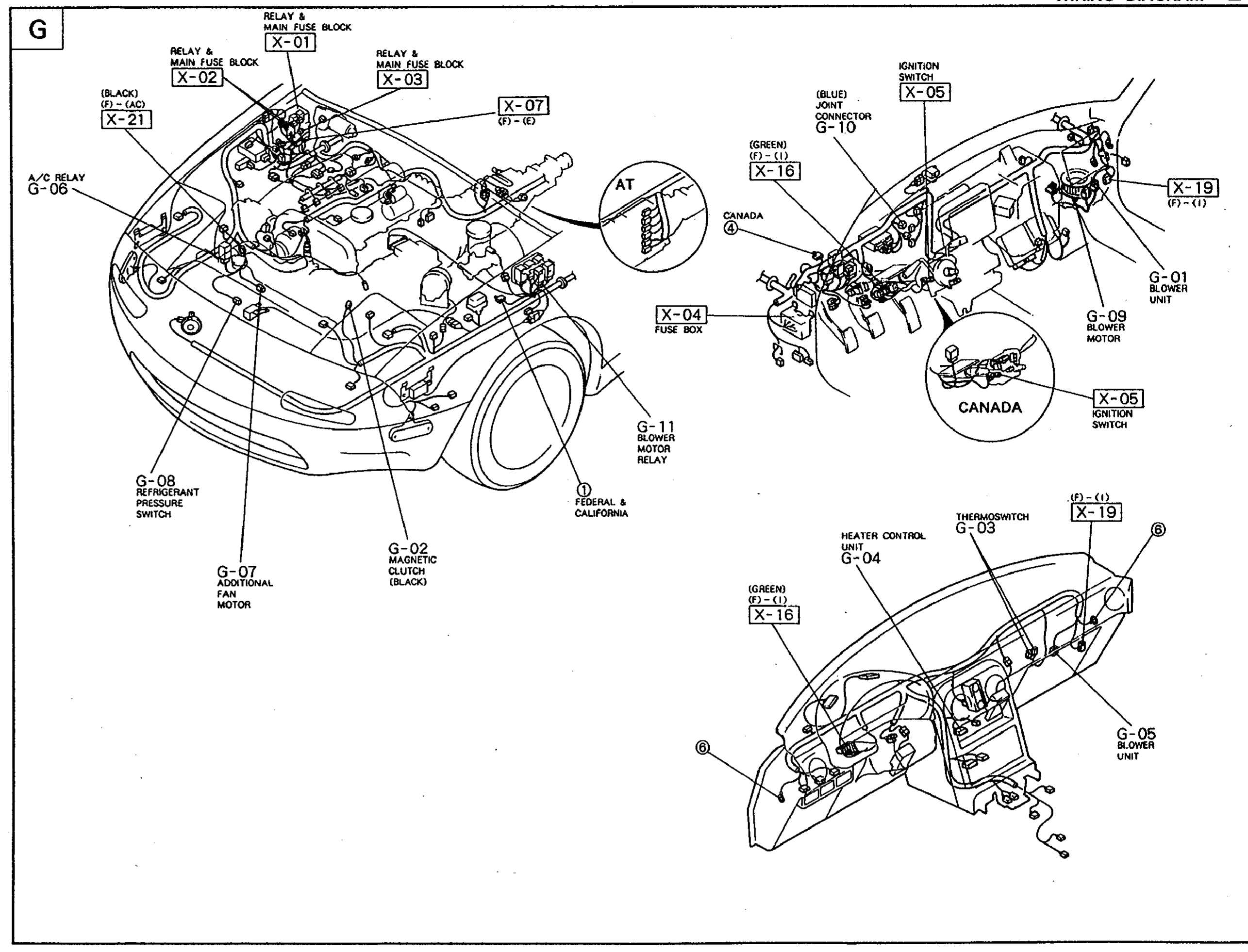
1X-01 / X-02 / X-03(Relay & main fuse block (engine bay))
2X-04(Fuse box (driver kick panel))
3X-05(Ignition switch)
4X-07((7)-(2) in-line connector)
5X-16(Joint connector G-10, (P)-(1) — BLUE on engine bay side, GREEN on dash side)
6X-19((P)-(1) in-line connector)
7X-21(Joint connector)
8G-01(Blower unit, dash)
9G-02(Magnetic clutch (BLACK), engine bay)
10G-03(Thermoswitch, under dash)
11G-04(Heater control unit (GREEN), under dash)
12G-05(Blower unit, lower dash)
13G-06(A/C relay, engine bay)
14G-07(Additional fan motor (P)-(1), engine bay)
15G-08(Refrigerant pressure switch, engine bay)
16G-09(Blower motor, dash)
17G-11(Blower motor relay, engine bay)