
WIRING DIAGRAM Z — Engine Control System Component Locations (Sheet B-1b)
Z-31wiring diagramCanada-spec under-dash inset shows the same under-dash routing with two callouts (1, 2).
Engine Control System — Component Locations (Sheet B-1b)
Component LocationFig. fig1
Physical locations on the engine bay (left) and under-dash (right). AT inset and Canada inset shown where applicable.
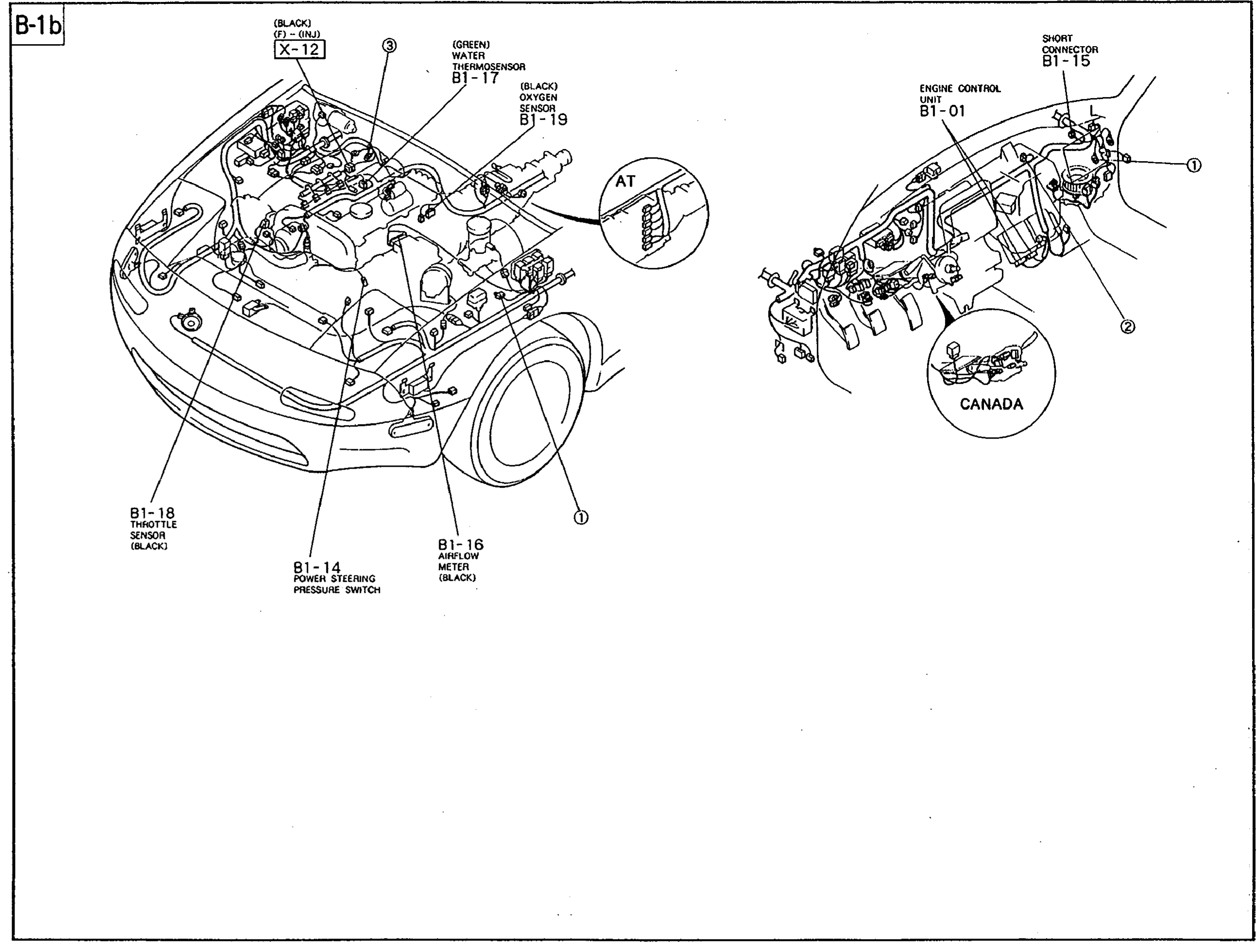
1X-12(Bulkhead connector — left fender, black)
2B1-14(Power-steering pressure switch — on power-steering line)
3B1-15(Short connector — under-dash)
4B1-16(Air-flow meter — on intake air boot, black)
5B1-17(Water thermosensor — on engine block, green)
6B1-18(Throttle sensor — on throttle body, black)
7B1-19(Oxygen sensor — exhaust manifold, black)
8B1-01(Engine control unit — under-dash on firewall)