
Wiring Harness Layout (F-1)
Z-57wiring diagramLayout drawing pairs with the F-1 schematic on Z-56.
F-1 Harness Component Locations
Component LocationFig. fig1
F-1 (turn signal, hazard, stop, back-up, horn, high-mount stoplight) harness component locations in engine bay, body, and dash.
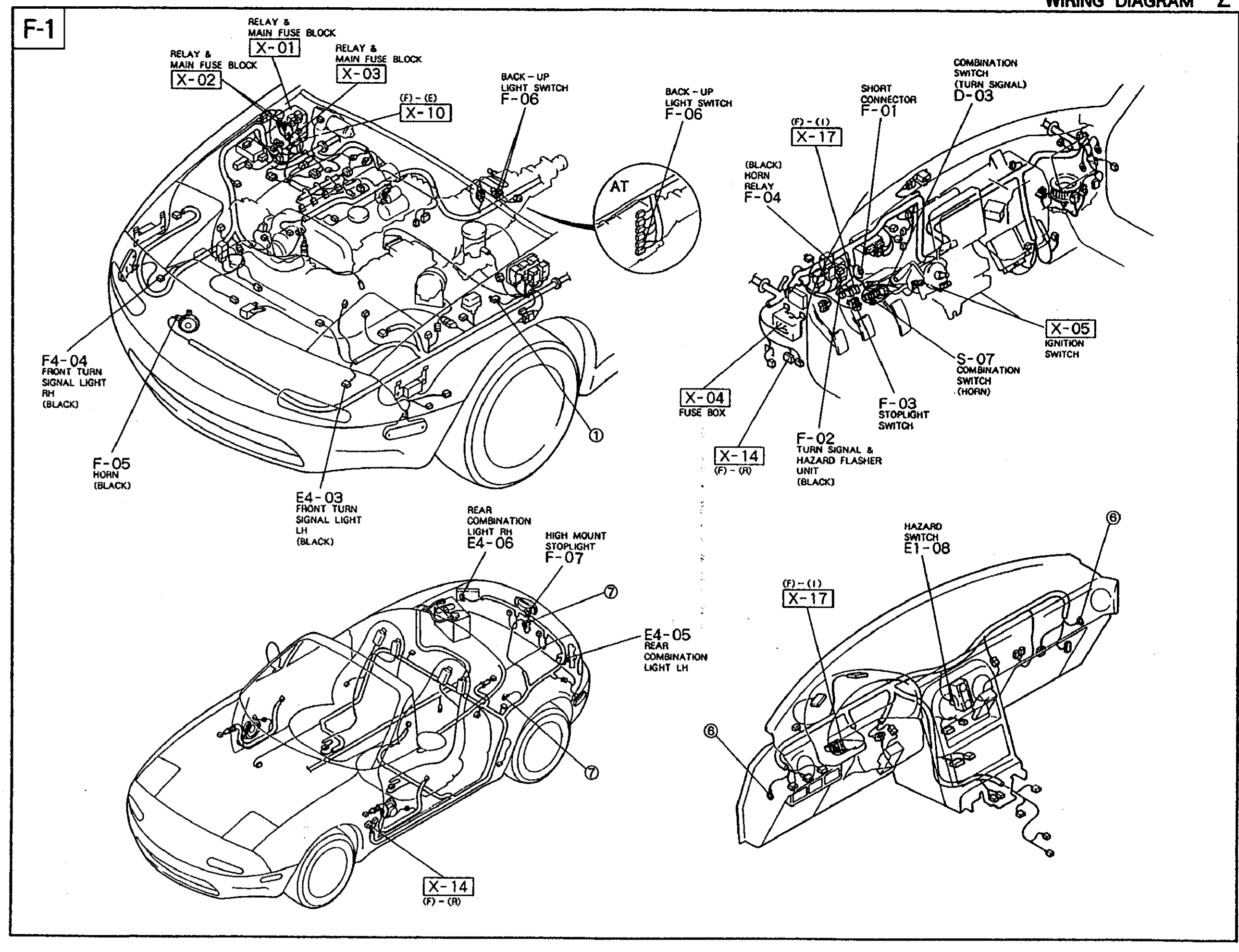
1X-01 / X-02 / X-03(Relay & main fuse block (engine bay))
2X-04(Fuse box (driver kick panel))
3X-05(Ignition switch)
4X-10((7)-(2) in-line connector for back-up light switch (A/T))
5X-14(Ground point (7)-(9), dash and rear floor)
6X-17(In-line connector (7)-(1) on dash harness)
7D-03(Combination switch (turn signal), column)
8S-07(Combination switch (horn), column)
9E1-08(Hazard switch, dash centre)
10F-01(Short connector)
11F-02(Turn signal & hazard flasher unit (BLACK), under dash)
12F-03(Stoplight switch, brake pedal bracket)
13F-04(Horn relay (BLACK), relay & main fuse block)
14F-05 (engine bay)(Horn (BLACK))
15F-05 (M/T)(Back-up light switch on transmission)
16F-06 (A/T)(Back-up light switch on A/T)
17F-07(High-mount stoplight, decklid)
18F4-03(Front turn signal light LH (BLACK))
19F4-04(Front turn signal light RH (BLACK))
20E4-05 / E4-06(Rear combination lights LH/RH)