
EXHAUST SYSTEM
F-115parts diagramCOMPONENTS
Removal / Inspection / Installation
- 1Remove in the sequence shown in the figure.
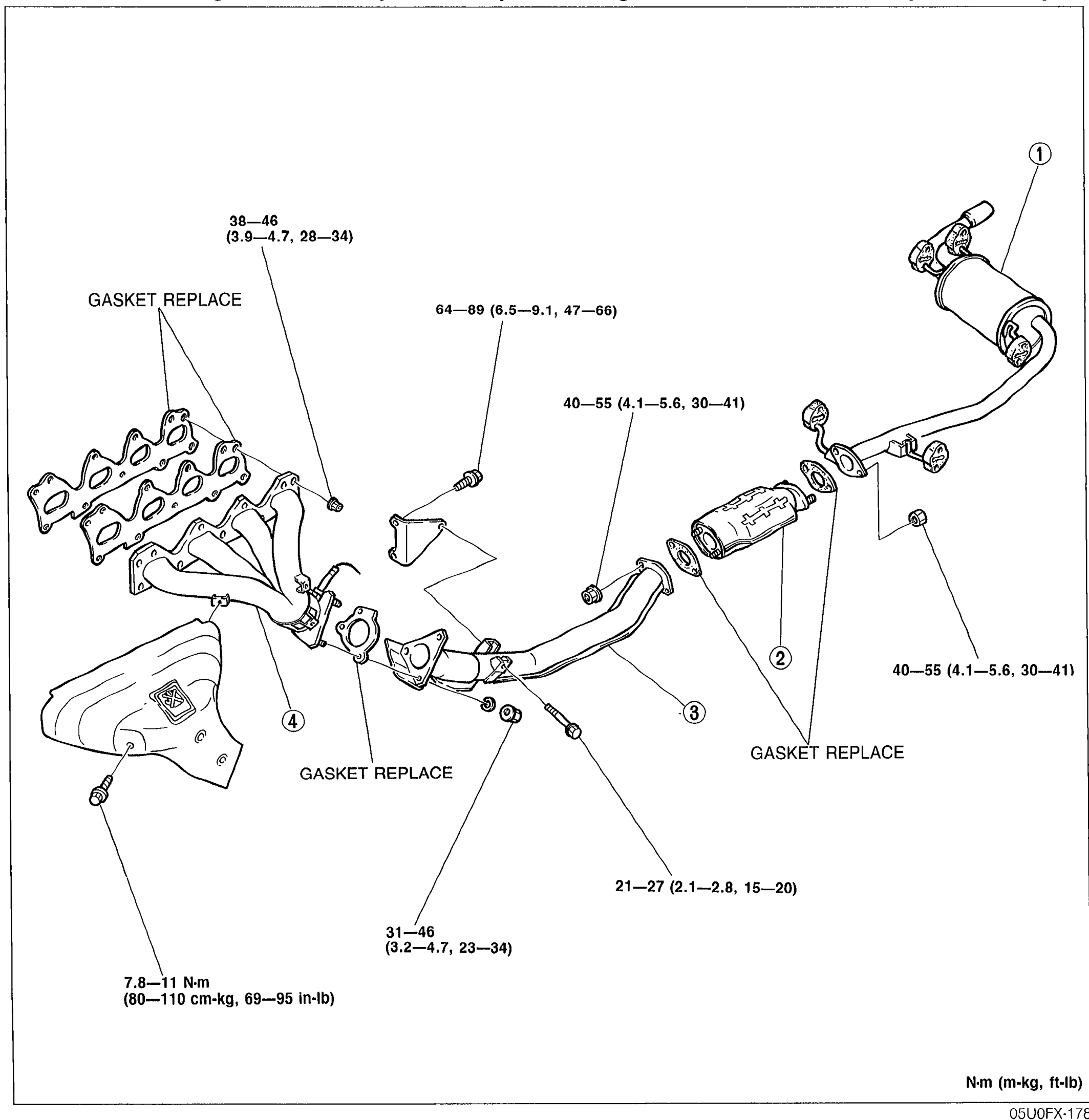 05U0FX-178
 - 2Check all components for damage, deterioration, and restriction and repair or replace as necessary.
- 3Install in the reverse order of removal.When installing the exhaust system components, tighten all fasteners to the specified torque.
Parts DiagramFig. fig1
| Specification | Value |
|---|---|
| Tightening torque (exhaust manifold to head) | ≈373 - 451N·m |
| Tightening torque (manifold to front pipe) | ≈628 - 873N·m |
| Tightening torque (catalytic converter joints) | ≈392 - 539N·m |
| Tightening torque (exhaust hanger) | ≈206 - 265N·m |
| Tightening torque (front pipe joint) | ≈304 - 451N·m |
| Tightening torque (heat shield) | ≈76 - 108N·m |
Tightening torque (exhaust manifold to head)
373 - 451N·m
Tightening torque (manifold to front pipe)
628 - 873N·m
Tightening torque (catalytic converter joints)
392 - 539N·m
Tightening torque (exhaust hanger)
206 - 265N·m
Tightening torque (front pipe joint)
304 - 451N·m
Tightening torque (heat shield)
76 - 108N·m