
CONTROL SYSTEM - Airflow Meter
F-135prose procedureAIRFLOW METER
Inspection
Airflow Meter Inspection
- 1Remove the airflow meter. (Refer to page F-92.)
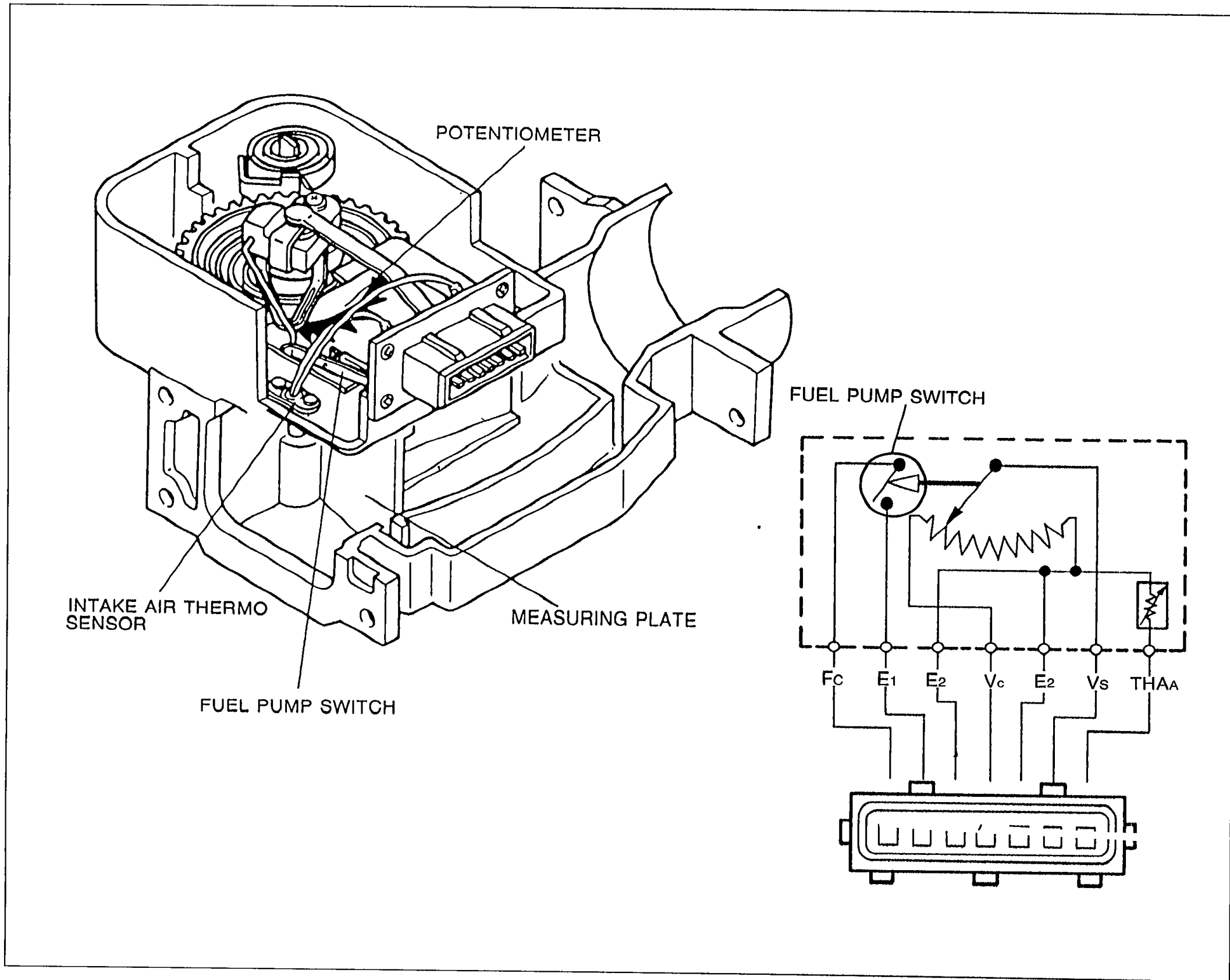 69G04A-177
 - 2Check the airflow meter body for cracks.
- 3Verify that the measuring plate moves smoothly.
- 4Disconnect the connector from the airflow meter.
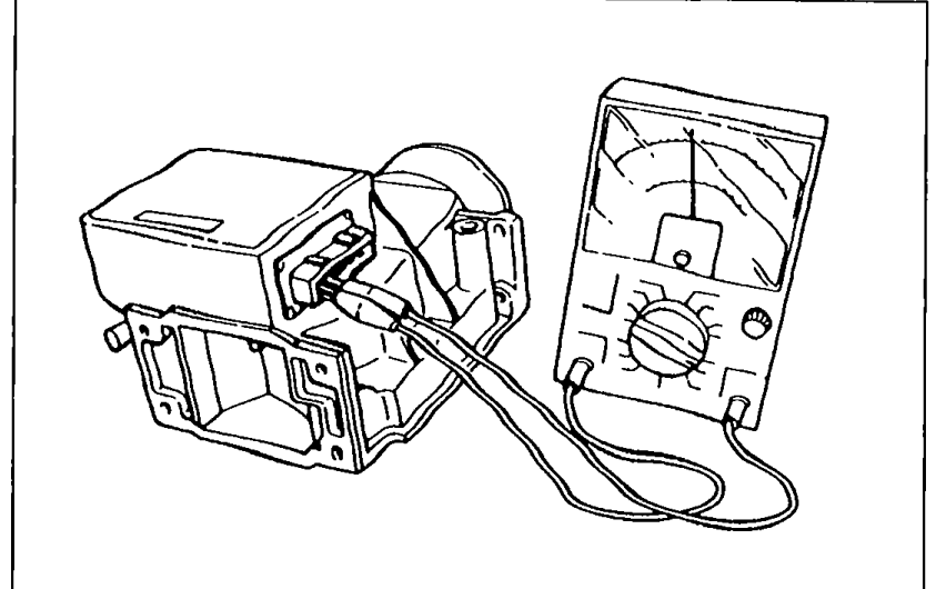 05U0FX-206
 - 5Move the measuring plate and check for resistance between the terminals with an ohmmeter.
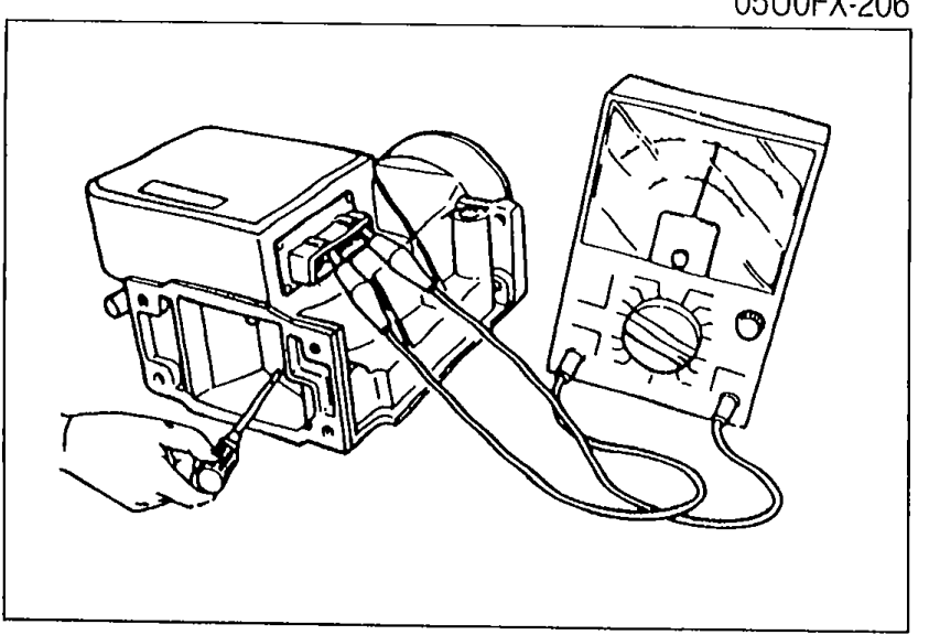 05U0FX-207
 - 6Connect the airflow meter connector after checking.
Airflow Meter Resistance
E2 ↔ Vs
Condition
Resistance (Ω) Fully closed200—600
Resistance (Ω) Fully open20—1,000
E2 ↔ Vc
Condition
Resistance (Ω) Fully closed200—400
Resistance (Ω) Fully open200—400
E2 ↔ THAA (Intake air thermosensor)
Condition−20°C (−4°F)
Resistance (Ω) Fully closed13,600—18,400
Resistance (Ω) Fully open13,600—18,400
E2 ↔ THAA (Intake air thermosensor)
Condition20°C (68°F)
Resistance (Ω) Fully closed2,210—2,690
Resistance (Ω) Fully open2,210—2,690
E2 ↔ THAA (Intake air thermosensor)
Condition60°C (140°F)
Resistance (Ω) Fully closed493—667
Resistance (Ω) Fully open493—667
E1 ↔ Fc
Condition
Resistance (Ω) Fully closed∞
Resistance (Ω) Fully open0