
OUTLINE
F-6parts diagramCruise control actuator shown — applicable to cruise-control-equipped variants.
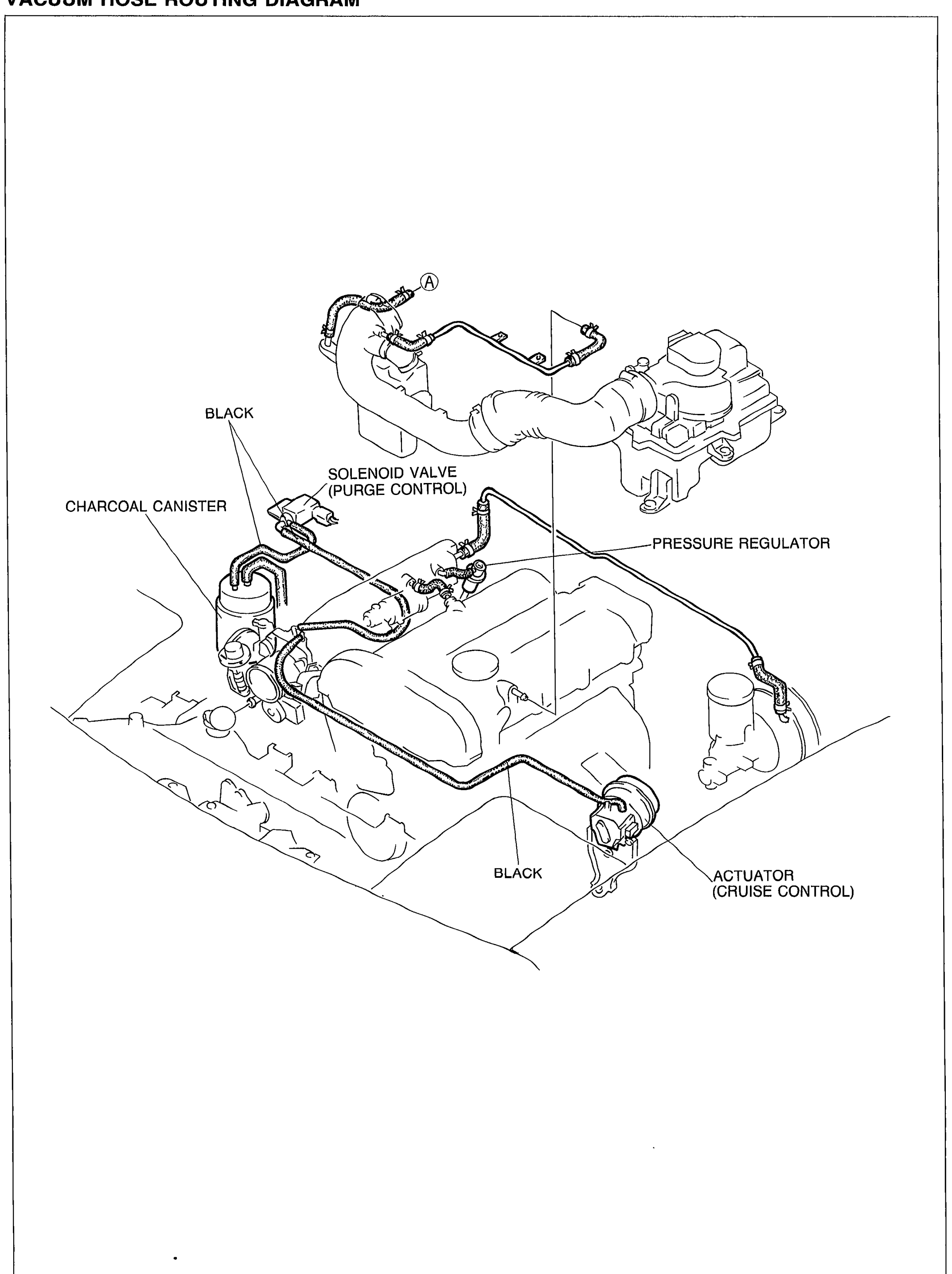
VACUUM HOSE ROUTING DIAGRAM
Component LocationFig. fig1
Vacuum hose routing over the engine showing the charcoal canister, purge-control solenoid valve, pressure regulator, and cruise-control actuator connections. BLACK markings call out specific hose runs.
05U0FX-006
1Charcoal canister(left)
2Solenoid valve (Purge control)(upper-center)
3Pressure regulator(right)
4Actuator (Cruise control)(bottom-right)
5BLACK (hose)(upper-left near solenoid valve)
6BLACK (hose)(lower-center near actuator)
7(A)(upper-center hose junction)