
INTAKE AIR SYSTEM
F-95prose procedurePage printed step numbers as 1,2,3,4,5,6,7,8 (injector harness), 8 (intake manifold bracket), 9 (intake manifold) — step 8 appears twice on the page. Renormalised here to monotonic 1–10 with notes preserving the original numbering.
INTAKE MANIFOLD
Removal
WARNING
Before removal, release the fuel pressure from the fuel system to reduce the possibility of injury or fire. (Refer to page F-101.)
Removal
- 1Remove the throttle body. (Refer to page F-94.)
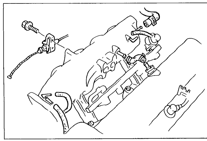
- 2Remove the air valve.
- 3Disconnect the vacuum hoses.
 05U0FX-112
 - 4Remove the accelerator cable.
- 5Disconnect the fuel hoses.
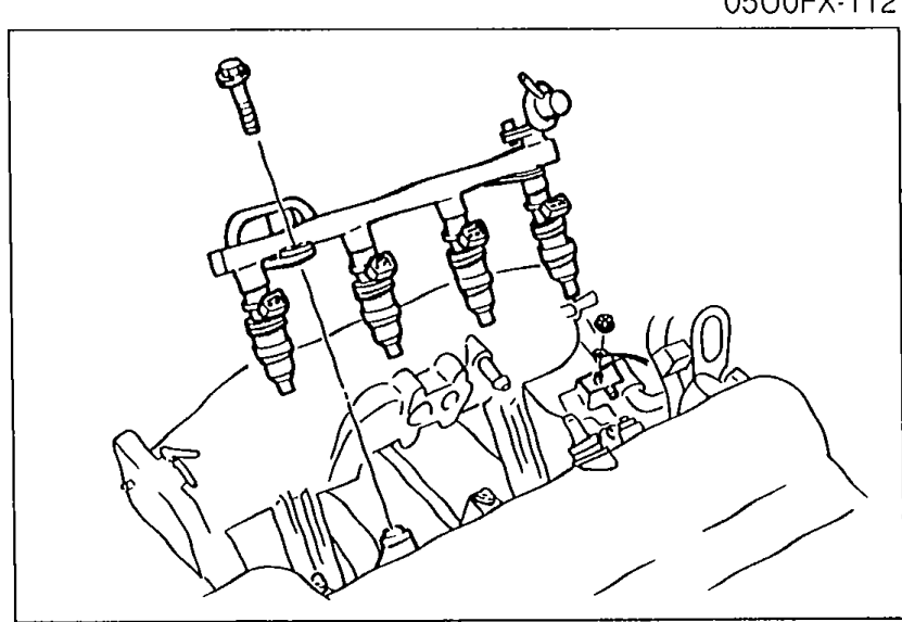
- 6Disconnect the connectors from the injectors.
- 7Remove the delivery pipe and injectors.
 05U0FX-113
 - 8Remove the injector harness.Page numbers step 8 twice; this is the first '8.' as printed.
- 9Remove the intake manifold bracket.Printed as '8. Remove the intake manifold bracket' — page repeats step number 8.
- 10Remove the intake manifold.Printed as '9.' on the page.
 05U0FX-114
Installation
Install in the reverse order of removal.
NOTE
Use a new mounting gasket.
| Specification | Value |
|---|---|
| Tightening torque — Intake manifold and delivery pipe | ≈186 - 245N·m |
| Tightening torque — Injector harness and bracket | ≈76 - 108N·m |
Tightening torque — Intake manifold and delivery pipe
186 - 245N·m
Tightening torque — Injector harness and bracket
76 - 108N·m